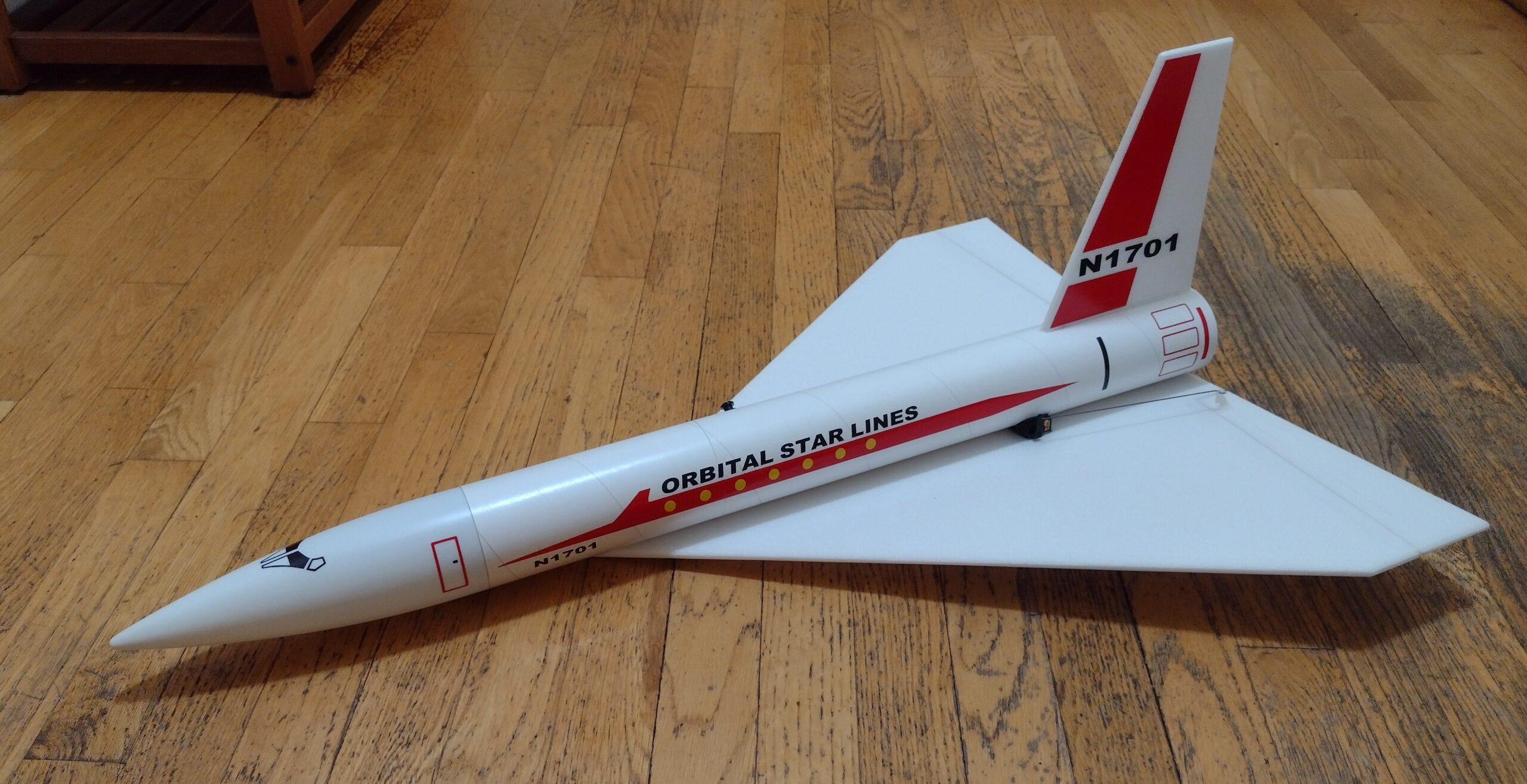
The Orbital Starliner R/C Rocketplane kit is a 3.5x upscale of a classic 1960’s design. It comes with a plastic nose cone, 2.6″ white tubing for the body, 6mm depron wing and tail surface. Spars are pre-installed and rail button holes are pre-punched, elevons are pre-hinged. Construction is very simple and takes about an hour and a half. Length 29″, wingspan 20″, weight 9 oz. rtf. For 24mm E-6 reloadable composite motors only. Excellent cut vinyl decals available separately from Stickershock23.com Please refer to the General information for all kits tab above, then read these instructions completely before starting assembly. CG location for rocket flight: 10.5” forward of the rear end of the wing.
Unpacking your kit:
The kits are packed to protect them in shipping, but the contents are fragile so unpack carefully. Carefully cut the tape holding the tubes in the box, then unwrap/lightly cut the plastic wrap to free the tubes, the spar may be packed in the tubes and the baggie with the little parts and nose cone will be in the tubes as well. Carefully cut the tape holding the cardboard wing protector in the box and carefully remove it, don’t pull hard or bend it. Then carefully cut the tape holding the cardboard top piece to the bottom. There may be some sticky tape holding the cardboard to the bottom cardboard piece, carefully peel it being sure not to bend anything. Once the top cardboard is free you can see the foam wing/tail parts, there are little fragile pieces in here, so unwrap carefully. It may be best to use an exacto to lightly cut the plastic wrap and carefully remove it without cutting into the foam. Make sure everything is free before you remove the pieces to avoid breaking anything. Kits contain one or two scrap pieces for repairs if you damage anything in construction or flight, just cut and patch in a spare piece of the foam if needed using foam safe CA+.
Welcome to the world of rocket boosted radio control gliders. This is not a model for a novice RC pilot, but anyone who is comfortable with RC flying of a medium speed model should be fine. Read through the instructions, look at the photos and be sure you understand the step before committing to cutting or glue.
Identify all pieces, the kit should contain:
1 wing taped together
1 Nose Cone
1 vertical stabilizer
2 control horns/Pushrods
2 body tubes and a coupler or 1 body tube.
Motor mount
3 13/16″ x 2.5″ wide strips to center the motor tube
Velcro(for battery and rx/bec attachment)
2 Rail buttons with t nuts/screws
Lead weight
Notes before starting:
Foam safe CA+(Bob smith super gold + is good) is the only glue recommended for construction. You will also need foam safe accellerator to set the glue.
I use a straight edge and exacto knife to put a small 1/16″ bevel on the leading and trailing edges of the wing and vertical stab before assembly, this is easier than sanding and makes it look and fly a bit better.
Assembly:
- Install the rail buttons in the pre-made holes in the slotted body tube, t nut goes inside then a washer, collar and another washer goes on the outside and held with the small screw, don’t over tighten, just enough to keep them from unscrewing.
- If your kit came with a single body tube, ignore the next two steps.
- Glue the coupler into the end of the tube with the rail buttons in the non slotted end of the tube. Insert it about 1″ or about where it hits the forward t nut for the rail button.
- Glue the other non slotted body tube onto the coupler, there is an alignment line on both tubes with an arrow, keep these aligned as you glue the coupler in place so that the wing alignment line will be connected.
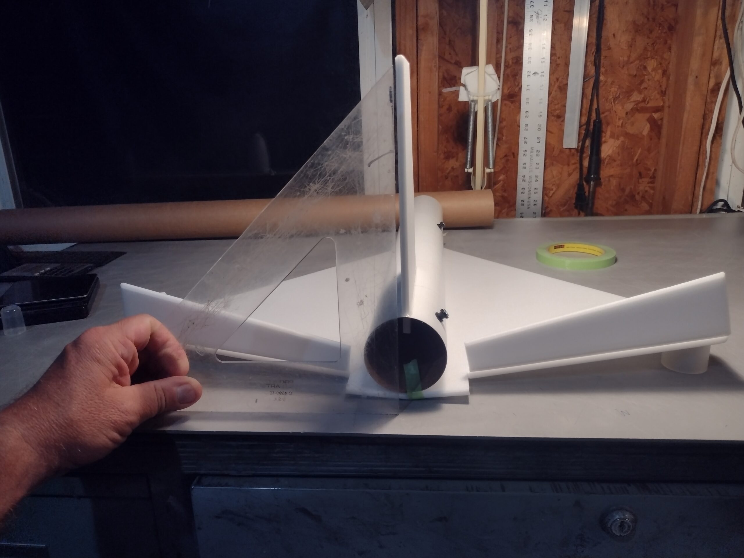
- Glue the vertical fin into place keeping it vertical. Apply a light filet to both sides of the vertical stab on the inside and outside of the body tube.
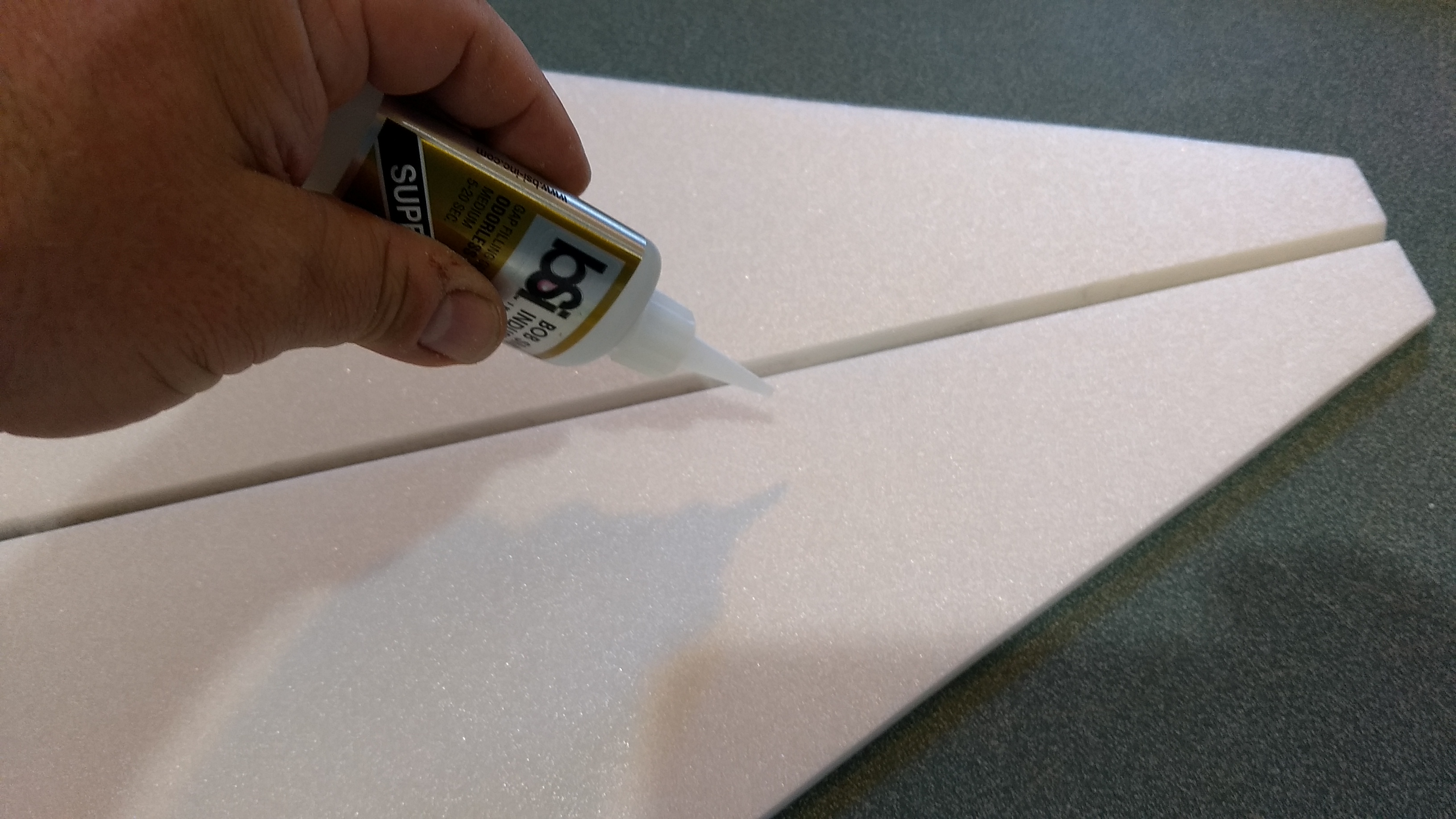
- Apply CA+ to the taped wing joint, and apply CA in a squiggle pattern about 1/2″ on either side of the wing joint and on either side of the pencil mark on the body tube.
- Set the body tube on a table upside down with the stab pointing down. Lay the wing over the body tube and make sure the rear of the wing is even with the rear of the body tube. Use the alignment line on the tube as a guide to keep the wing straight. Hold the wing in place with your hands till the glue sets. You want to be sure the wing tips are about the same distance from the table top and that the vertical stab stays vertical. The actual dihedral amount isn’t super critical, just so that it is about the same on each side, less dihedral will give a little longer glide, more will make it more stable in roll during glide. Use accelerator to help set the glue if needed. Make sure the glue is set before continuing. You can flip the model over as the glue sets and check the dihedral off the top of the table on each side and make sure the tail is still perpendicular.
- Once set flip the model over. Apply a fillet on the top and bottom of the wing/body tube joint on both sides, I squeeze a small amount about every 1″ along the joint and it wicks itself in. Use accellerator to set the glue before you continue.
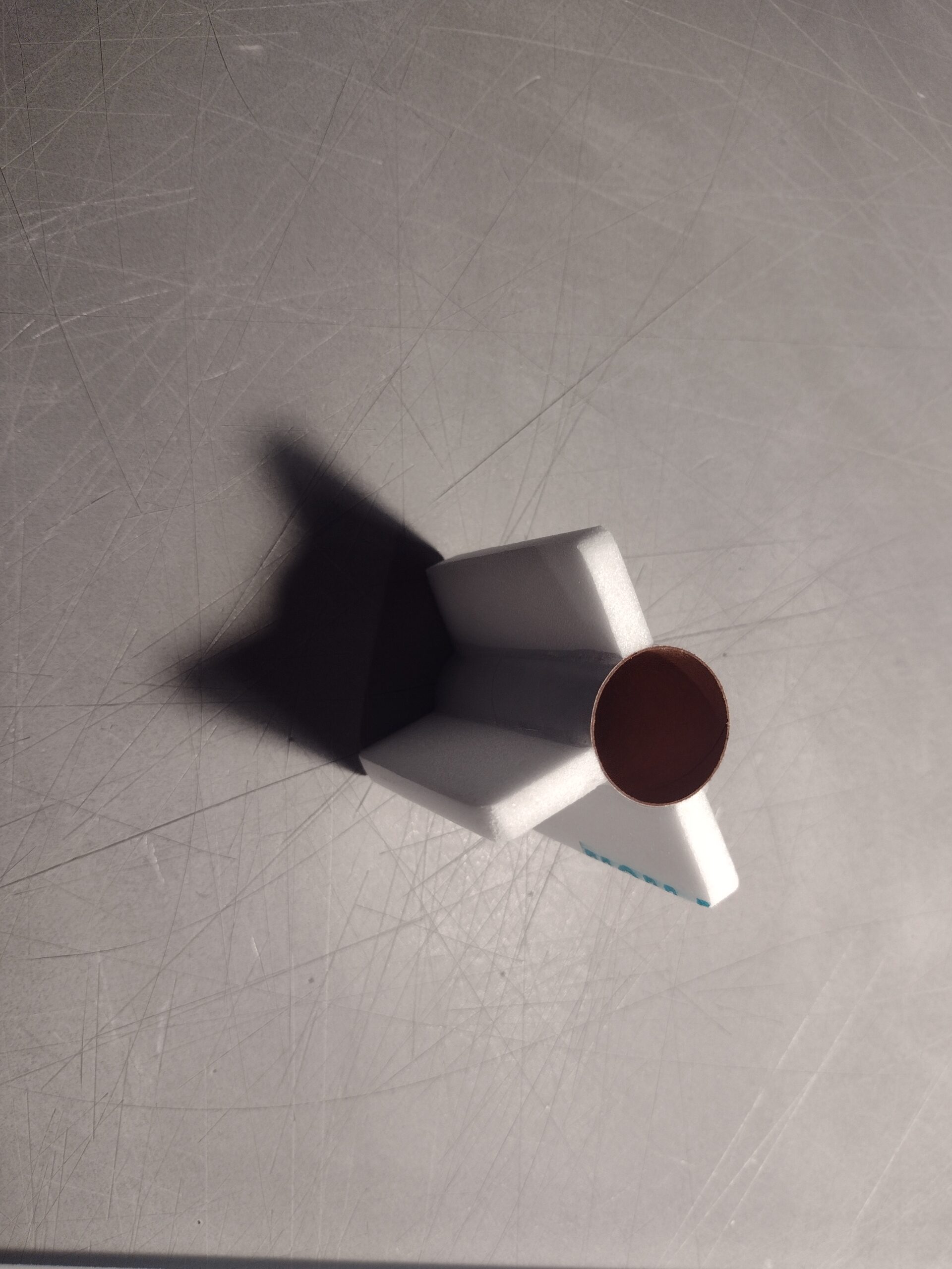
- Glue three 2.75″ long foam strips on the motor tube using foam safe CA+. These help center the motor tube in the body tube once you insert it into the body tube. Two tabs go on opposite sides and one tab on the bottom, the vertical stab tab will be the fourth tab when you install the motor mount. You can mark the tube or just do it by eye, it isn’t critical to be perfect but they should be about 90 degrees apart.
- The casing has a ring at the rear which keeps it from moving forward. There is no ejection so you don’t need a motor hook, I use a small piece of tape to make sure the motor doesn’t fall out.
- Test fit the motor mount into the body tube and under the fin tab. Make sure it fits, or sand the foam tabs lightly. Glue the motor tube in place, it will inset about 1/2″ from the end of the body tube. Put a fillet on each side of the motor mount tabs and fuselage.
- Glue each pushrod/control horn into the pre-punched holes on the top of each of the control surfaces. The control horn holes face forward and the pushrod should be closest to the body tube and angle inward. Apply a fillet around the control horn on the the prongs on the bottom of the wing to lock them in place.
The basic construction is now complete.
Radio Installation
Note: Your radio needs to be configured for Delta mixing, this means that the servo arms will move the same direction during elevator stick movement and opposite for aileron stick movement. Connect your servos to the receiver one in the aileron connection and one on the elevator connection and apply power. Use a servo arm at least 9/16” long and with holes small enough that there won’t be slop with the pushrod wire when installed. I use the hole furthest out on the servo arm, to maximize movement. On some servos there are a long two-ended servo arm, you can trim off one end and use that arm to get sufficient length. Zero out any trim settings on the transmitter.
- Connect each servo to a pushrod. If the pushrod is too tight, you can use twist an X-Acto knife in the servo arm hole to make it larger, but be careful and do not make it too large. The servo should be next to the body tube on the top of the wing, with the servo electrical wire pointing forward and the servo arm pointing toward the wing tip. Hold each servo in place so that the control surfaces are centered. With the model right side up look at it from the rear. Moving the transmitter stick back(up elevator) should move both elevons up. Moving the transmitter stick to the right should move the right elevon up and the left elevon down. If you can’t get the servo reversing to give you the right polarity try swapping aileron/elevator inputs to the receiver or turning the servos over and swapping the servo arms to the other side of the output shaft. If that is correct, continue.
- Cut a pocket into the body tube so that the servo will inset as far as possible and the control surface will remain level.
- The pushrods should naturally align to the servo. If not you can use a needle nose pliers to adjust the z bend to allow the servo to sit straight in the pocket in the body tube without having to put strain on the pushrod.
- Attach a lightweight 4″ to 8″ servo extension to each servo and then route the servo wire forward through the pocket and out the front of the body tube and re-connect to the receiver and power up the system. The wires just need to be long enough to reach out the front of the body tube to hook up to the receiver.
- With the radio still on, put a moderate amount of glue on the servo, being careful not to get any near the output shaft, and set it in place on the model next to the body tube keeping the control surface centered. Do the same to the other side. Make sure the glue is set before continuing. Apply a fillet of glue around the servo/wing to help secure it and let it cure being careful not to get any glue near the output shaft of the servo.
- Make sure the control surfaces are centered, use trims if needed. Now measure the control surface movement. Full elevator movement should be 1/2″ in each direction, aileron movement should be 1/4″ in either direction. measured at the inboard end of the surface. The outboard end will move more.
- If you have a flap/elevator mix you can program up elevator trim for boost and glide or you can use flight modes to set elevator trim separately for launch and glide and set that via one of the radio switches, if you use flight modes you can also set trims so that you can have independent boost and glide pitch and roll trim if needed. If you can’t set the up elevator trim to a switch on your radio you’ll have to manually put in boost and glide trim using the trim tabs which is hard to do while flying the model. My model needed no trim for vertical boost and the needed approximately 1/4″ of up trim for glide.
- Use the included Velcro to attach the receiver inside the top of the body tube far enough in that the nose cone won’t hit it. This allows you to be able to remove and replace the receiver if needed for repairs or for removing the servo wires.
- I attached the battery inside the front bottom of the body tube back far enough to clear the nose cone or inside the bottom of the nose cone with the remaining velcro. You may wait to do this till you balance the model to find the best spot without adding nose weight.
- I do not recommend painting the model, it is all white and this saves weight. If you fly in a wet area you may want to put some clear packing tape on the front bottom of the body tube to help protect it from water.
- If you use the stickershock markings after application use a hot hair dryer to soften the decal and press them into the foam with your thumb to really set them into place.
- Insert your heaviest loaded rocket motor into the motor mount and install the battery.
- Support the model upside down at the balance point indicated for boost. Glue pieces of the included lead weight in the nose or tail as needed to balance it or move the battery around. Do not try to fly the model too nose or tail heavy. Remember, a nose heavy model flies poorly, a tail heavy model flies once
- Re-install the receiver and battery
Flying: See the General Instruction link at the top for flying instructions. Be ready on the first few flights to keep the model straight till you have the trims set perfectly for boost and glide.
-
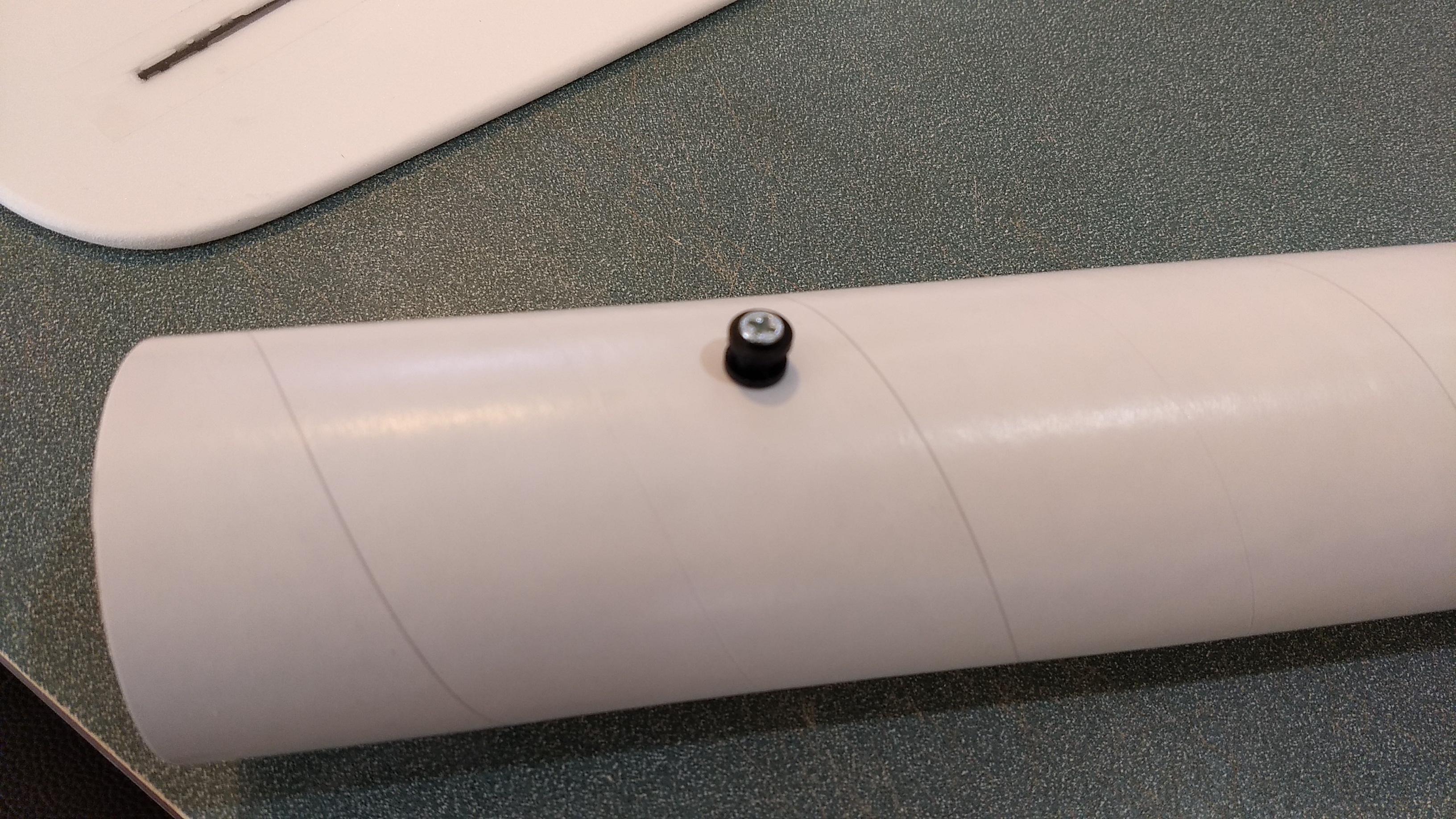
- Install the front and rear rail buttons
-
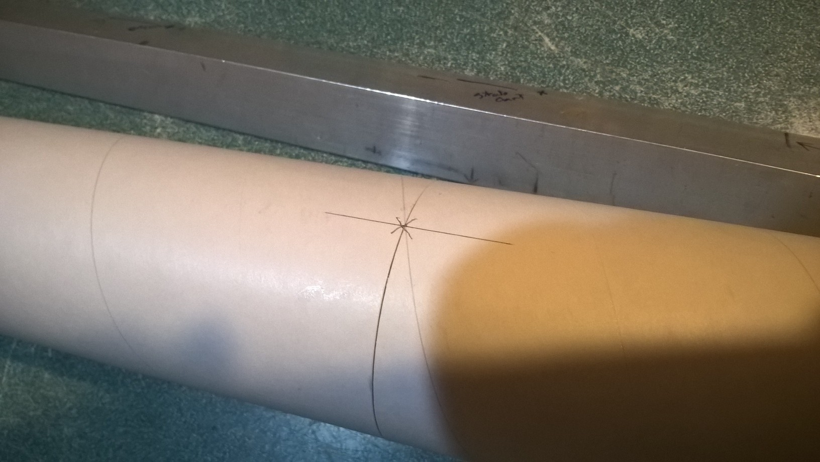
- Glue the two body tubes goether with the arrow lines aligned
-
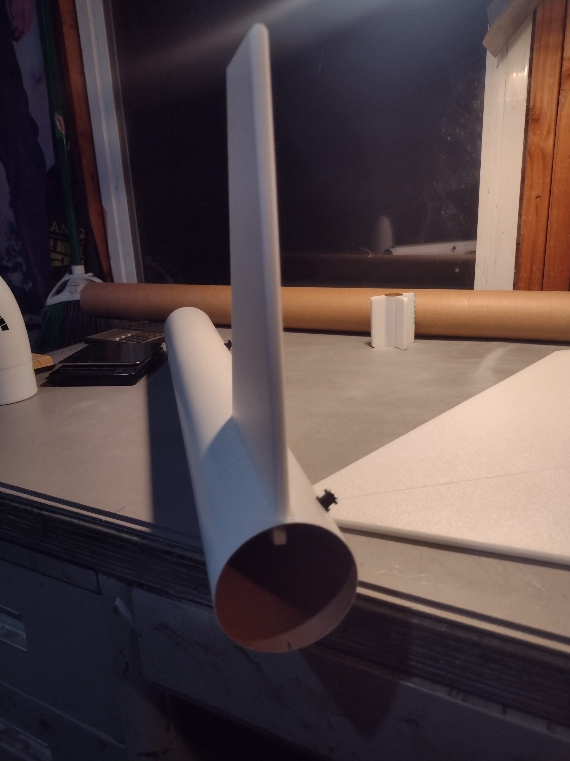
- Install the vertical fin
-
- apply glue the wing joint
-
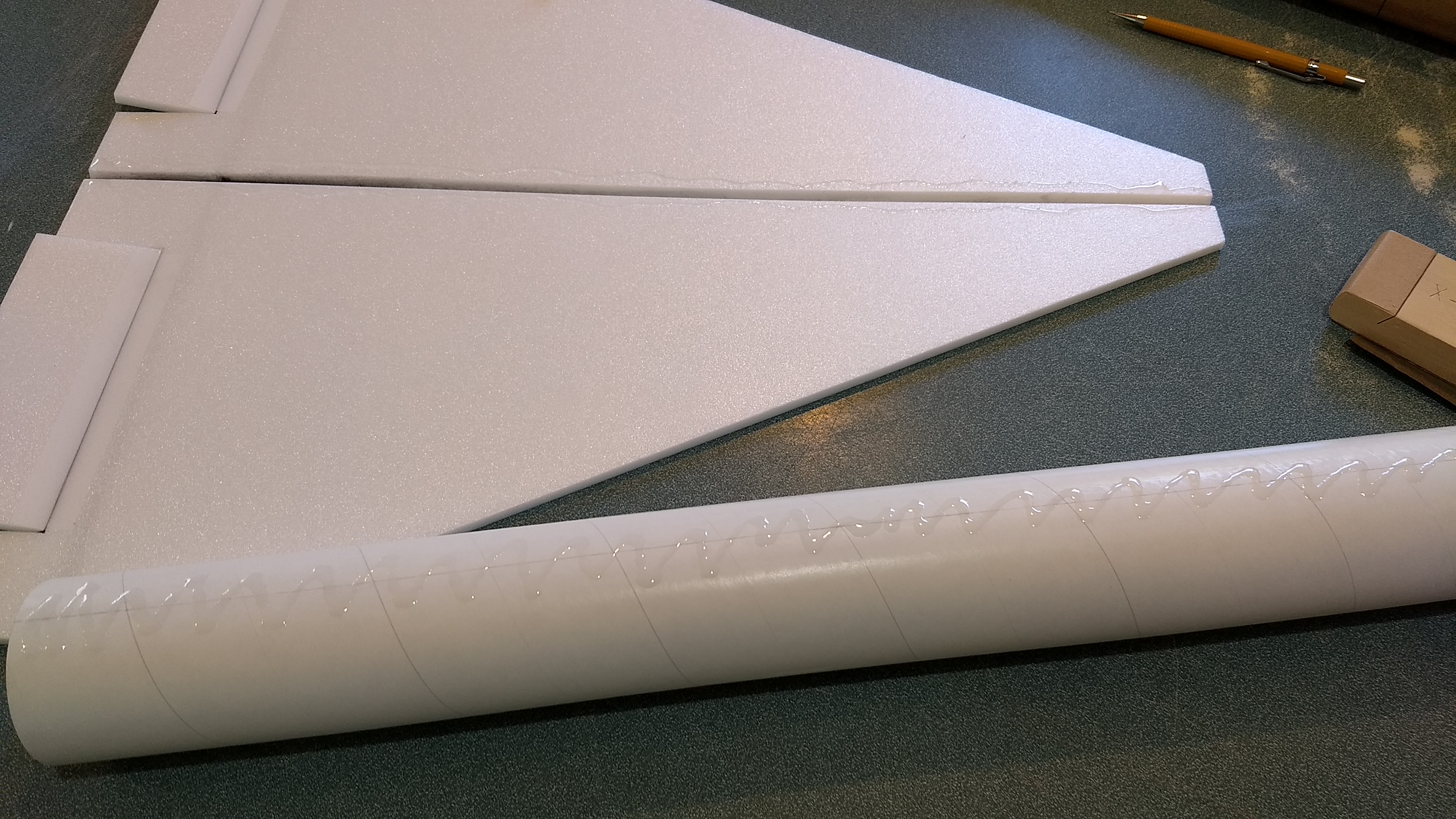
- apply glue to the body tube and wing joint
-
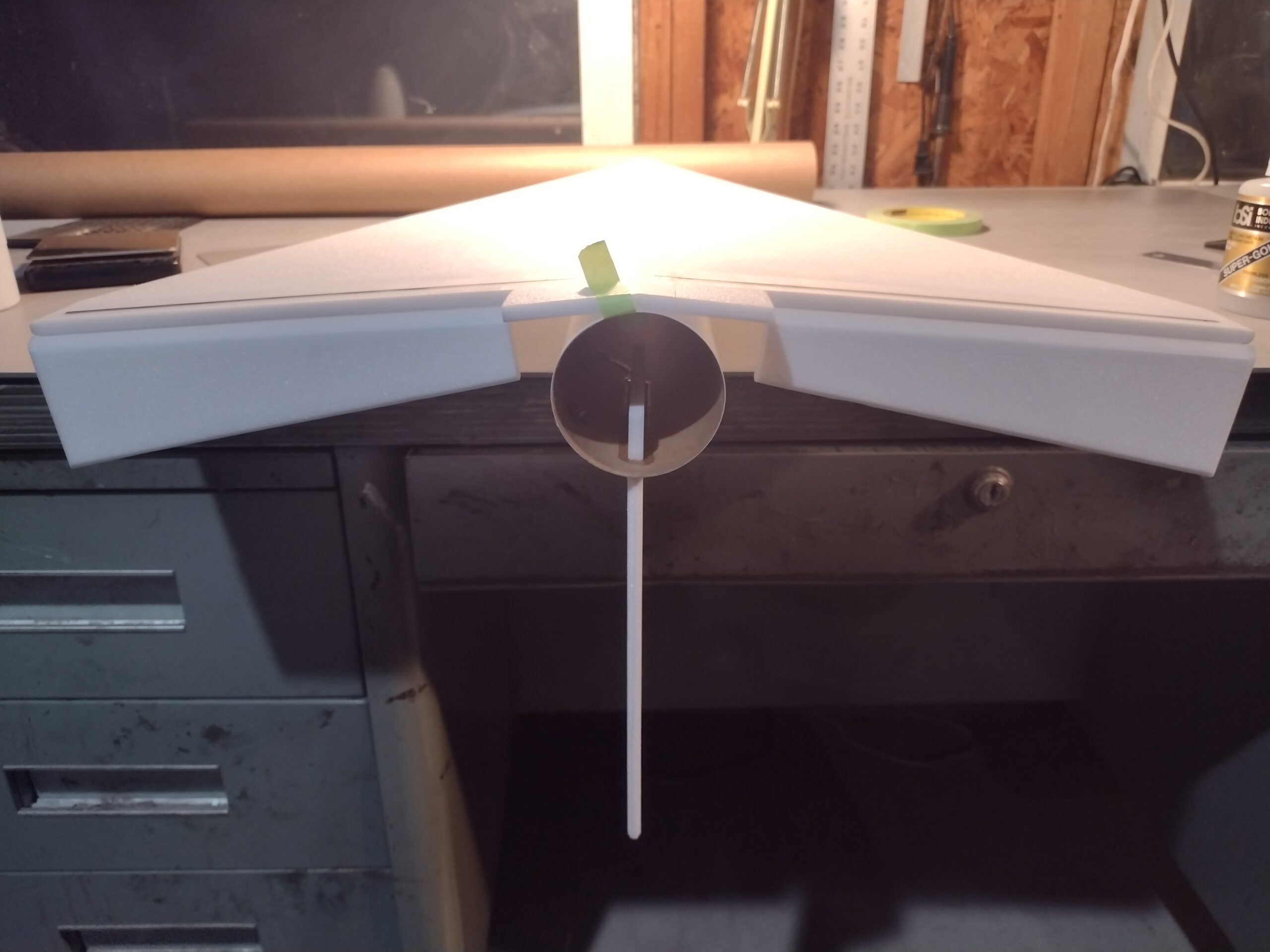
- Glue the wing to the fuse keeping the vertical stab vertical
-
- Double check the dihedral is the same on each side and stab is still vertical, let dry before proceeding.
-
- Glue foam strips on three sides of the motor tube
-
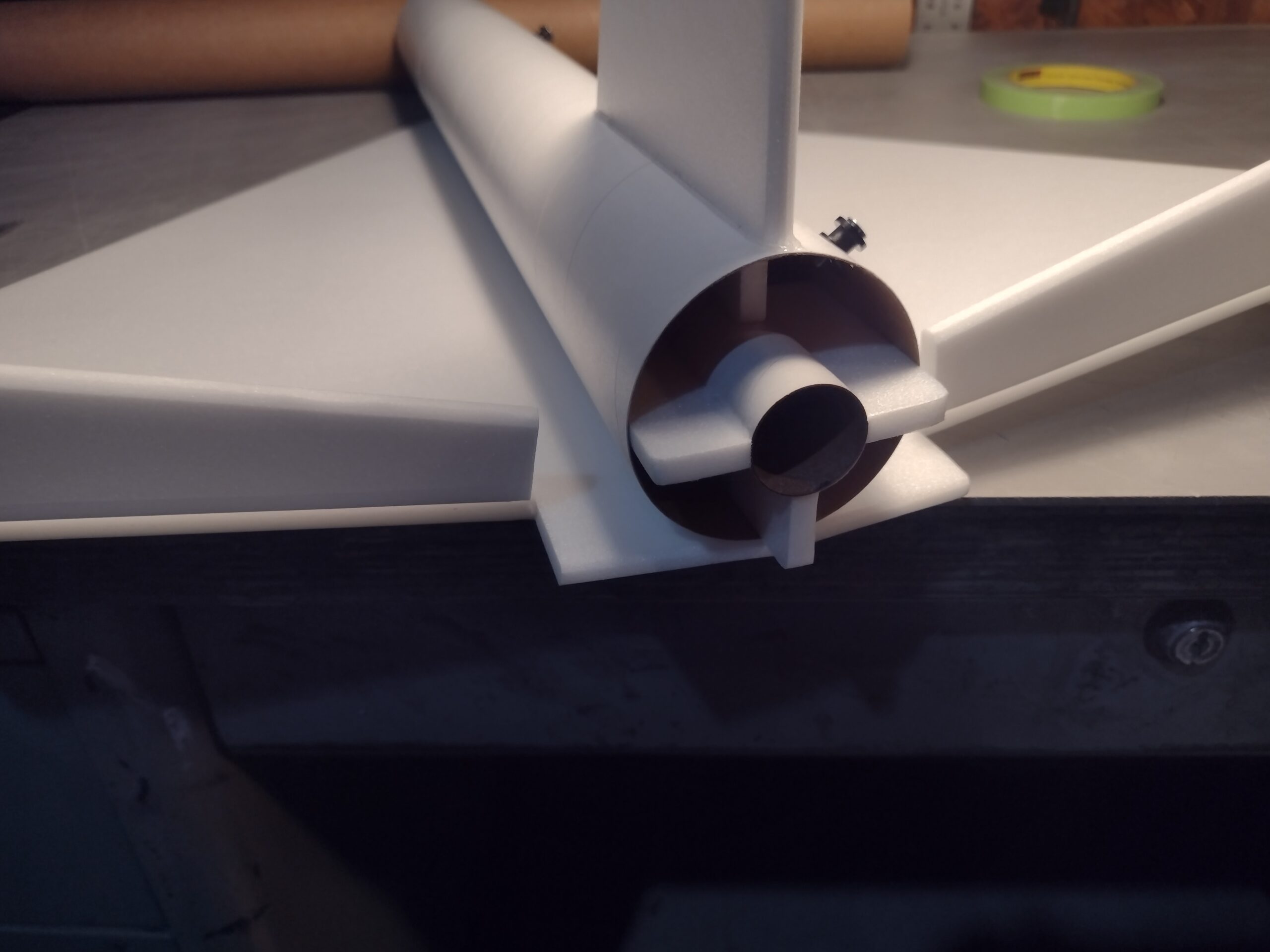
- Fit then glue in the motor tube inset about 1/2″
-
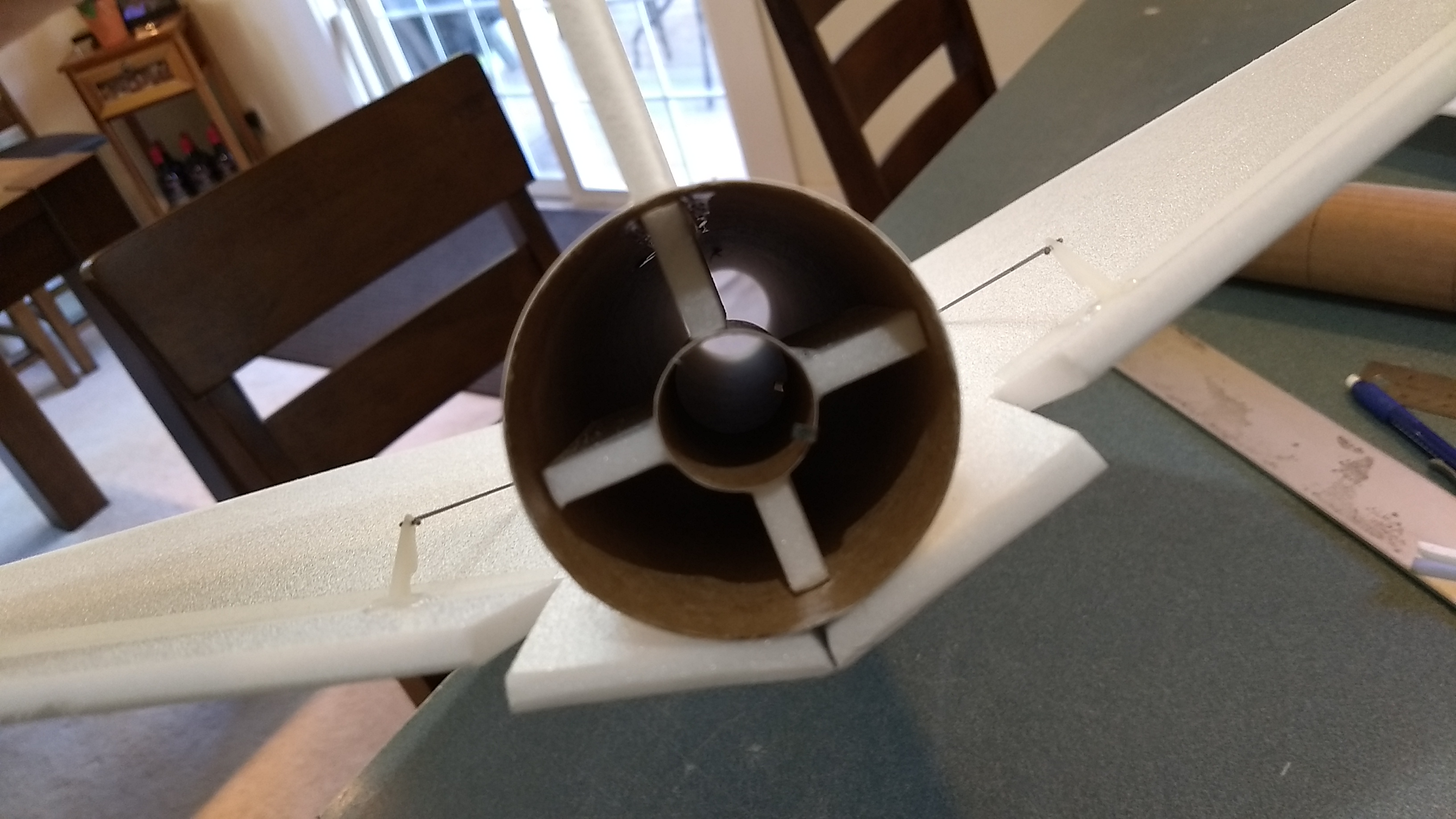
- Motor mount glued in place.
-
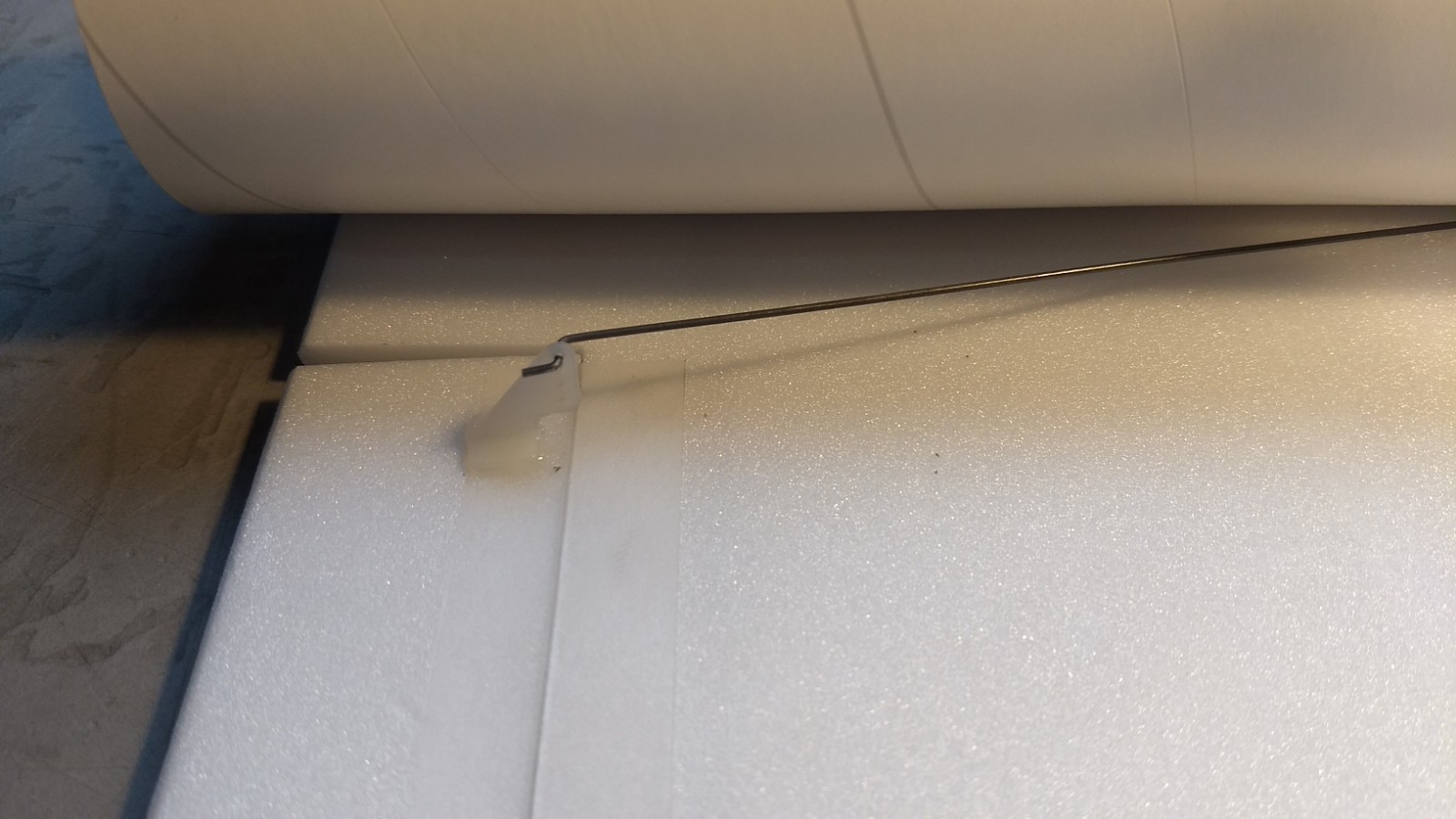
- Pushrods/horns glued in place.
-
- apply glue to the ends of the control horn prongs to lock them in place.
-
- Servo pocket cut in body tube.
-
- Servos installed and glued into pocket.
-
- Receiver velcrod into body tube, battery can also be installed in the tube or cone as needed for balance.
-
- Completed Model
-
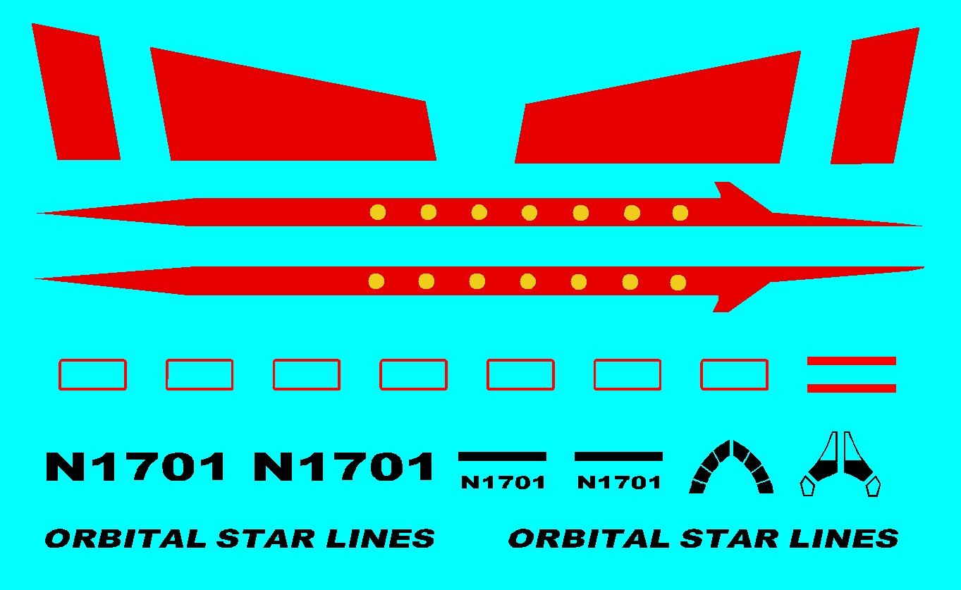
- Example of stickershock Decals