Flying 199 Rocket powered X-15 flights. Frank Burke NAR #69321 L2
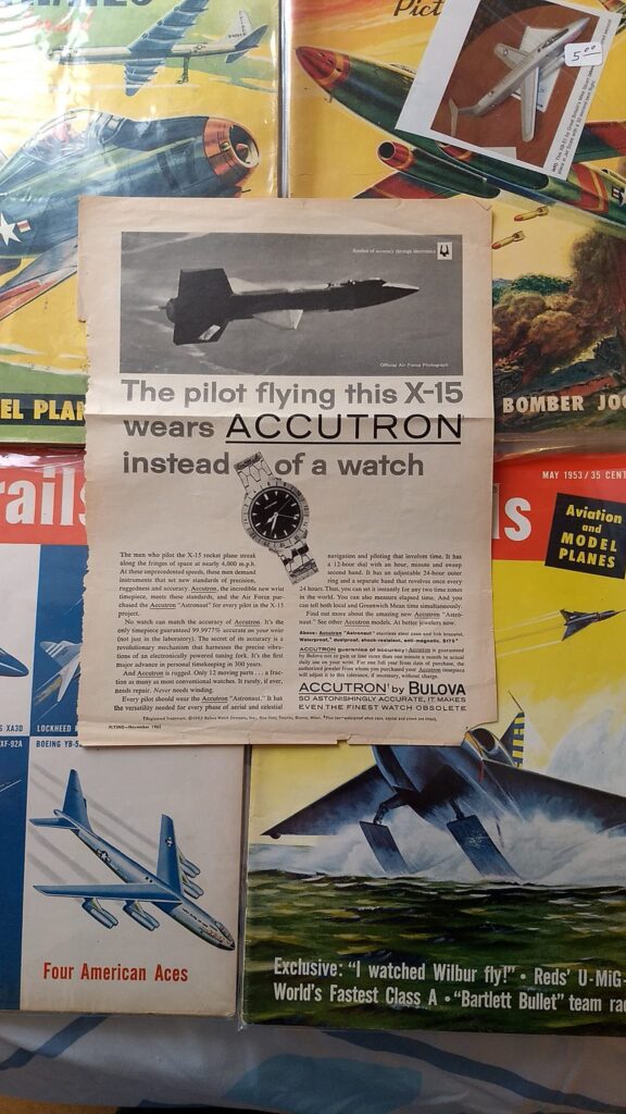
When I was a young boy just getting into rocketry in the mid seventies, I had a fascination with x-planes and in particular the x-15. There was something about that sleek black aircraft slung under the wing of a B-52 dropping and igniting the rocket motor and making a high speed run above Mach 6, or flying a ballistic trajectory into space and making an unpowered pinpoint landing. I dreamt of actually piloting my own x-15 into the bright blue sky under rocket power and coming in for a nose high landing right on the center line of the runway. Fortunately, I live in a time where electronics, rocket motors and materials have evolved to where this is now possible.
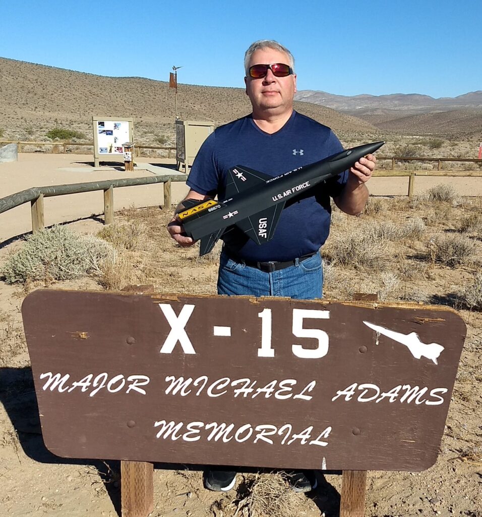
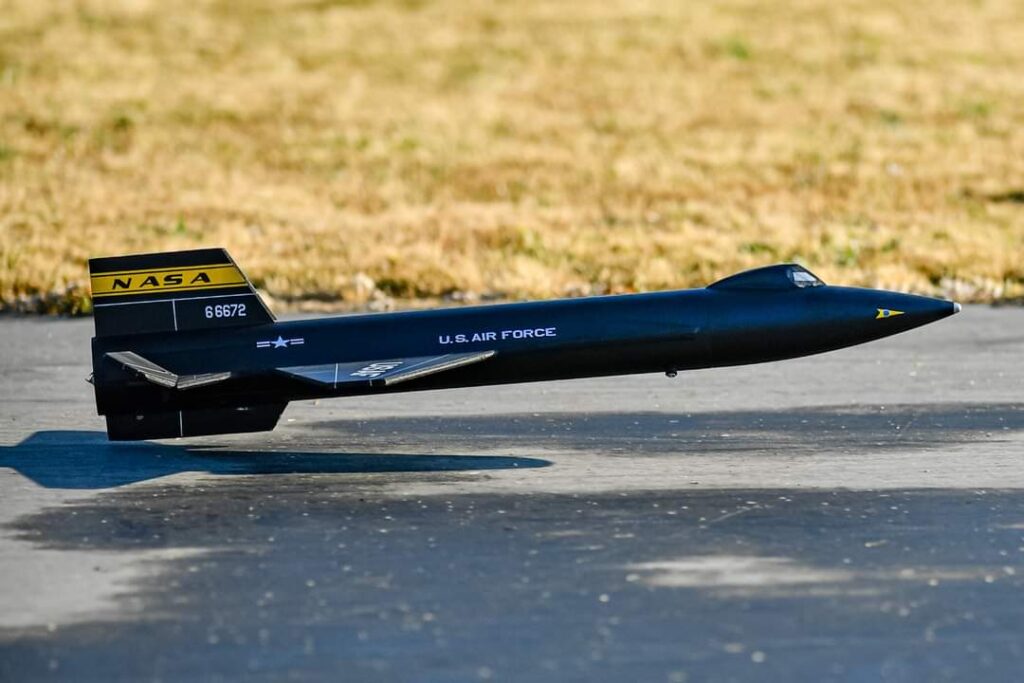
At a recent launch at the Lucerne dry lake bed I made a stopover at the memorial to pilot Mike Adams who was killed in X-15 number 3 near the end of the program. The memorial is located at the site where the forward wreckage of the aircraft was found. The three X-15 airframes flew a total of 199 rocket powered flights before the program was terminated, far exceeding its’ design criteria. This article documents my process in making my own 199 rocket powered piloted radio-controlled X-15 flights. I would build three airframes, one with each tail number, flying the exact number of flights that the originals did. I hope in some small way my tribute will encourage others to read about and learn about the X-15 and the people who designed, built, maintained and flew them.
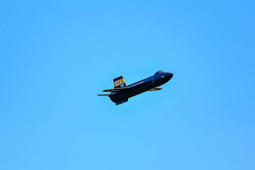
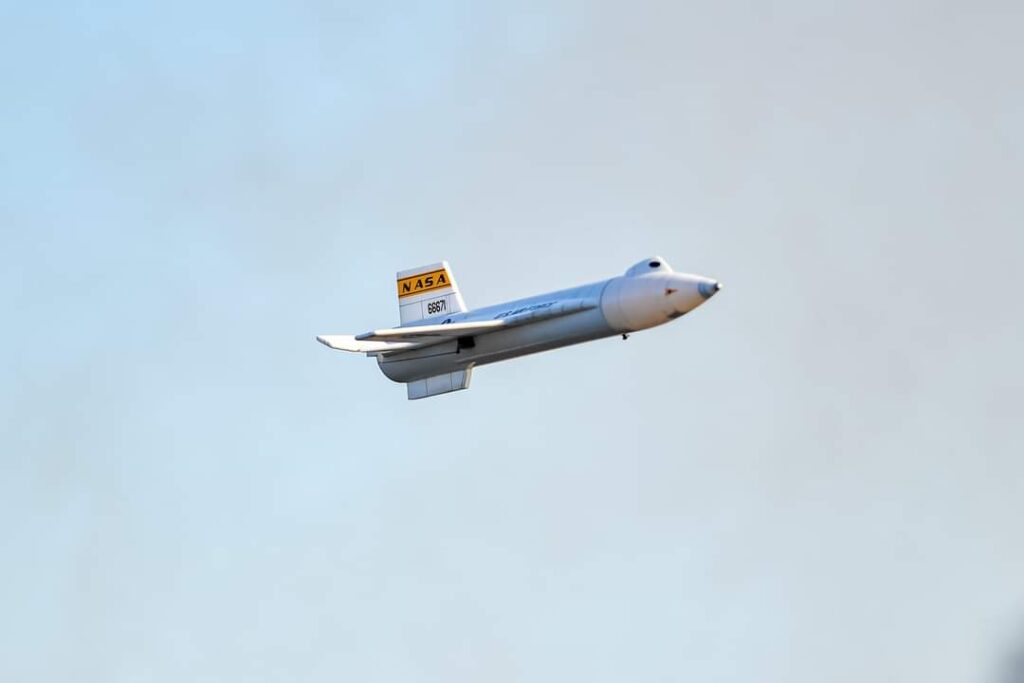
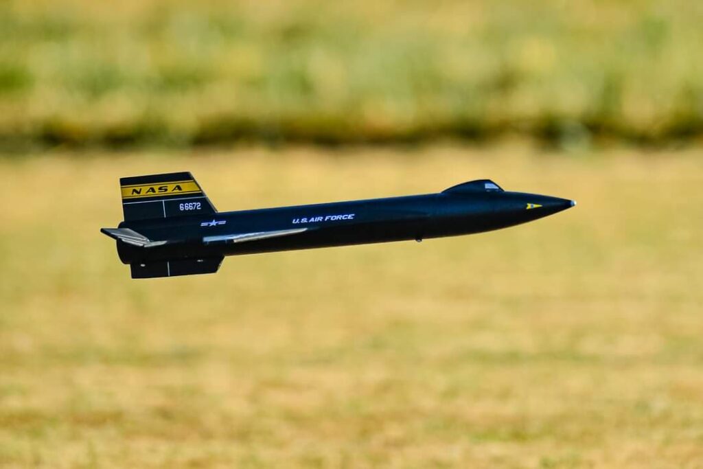
Aircraft tail number 66670 was the first X-15 built and flew 85 flights, tail number 66671 flew a total of 31 flights before it was damaged and then rebuilt as a longer version and flew 22 more flights in that configuration, the last two coated with a special ablative material and white protective overcoat to protect against heating. The final tail number 66672 flew 65 flights before it was lost in the single fatal accident of the program with pilot Mike Adams on board.
There are three major hurdles to making a rocket powered gliding X-15. The first is minimal wing area and high wing loading leading to a steep fast glide recovery. The second is dealing with the center of gravity shift as the tail mounted motor burns leading to a nose heavy glide condition. The third is the shape of the aircraft leading to a very far forward CG, near the leading edge of the wing at the root.
Designing a radio control rocket glider with a tail mounted motor requires up front planning. If the design comes out too heavy and requires a larger motor, it will also require more nose weight yielding higher wing loading and larger CG shift. It’s very easy to quickly overload the wings yielding an un trimmable or unflyable that has excessively high landing speeds. I prefer to size my designs so that I can trim the nose heaviness at burnout with the control surfaces, and not have any complex ballast dropping schemes. Where I fly, I cannot recover pop pod designs due to tall crop fields. The Model must be simple, strong enough for the boost speeds, light weight and self-contained.
Due to the amount of flights planned and to reduce cost I chose a 1/21 scale with a lightweight 2.6 in airframe which allowed me to use a standard PNC 80K nose cone. This led to an overall length of 28.25 inches. At this size and estimated weight, I would be able to use 18 mm reloadable composite rocket motors to get sufficient boost speed and altitude yet limit the propellant Mass so that the center of gravity shift would be minimized. For the flight surfaces my material of choice is called depron. It’s an extruded polystyrene foam sheeting in 6 mm and 3 mm thicknesses used in Europe primarily for insulation. It’s used often in R/C modeling because it has properties that make it far superior to any of the inexpensive foam boards or paper covered foam board material in that it’s lighter, stiffer, sands better, has a smooth surface on both sides and has some flexibility without snapping or kinking.
I made a few concessions to scale outline to help glide performance, save weight and make construction simpler. The full scale x15 did not use ailerons, instead using movable tail surfaces for both roll and pitch. I went with a similar approach with hinged horizontal tail surfaces for both roll and pitch, meaning I only needed two servos for control to help save weight and simplify linkages. The tail surfaces are horizontal and do not have anhedral like the real aircraft which allows simpler construction and stronger spar support.
I chose not to make the vertical stab wedge shaped to reduce drag during flight and make it stronger and simpler to construct. The real aircraft flew many of its early flights with an extended lower tail surface that was dropped before landing. This was found on later flights to be un-necessary for high-speed stability and in fact in flight profiles was a detriment to stability. I designed my model without the extended lower ventral which also meant I could belly land the airplane without damage.
Retractable gear was a non-starter due to weight criticality at this size, and flaps were not going to be needed or desired at the glide weight target. Droppable tanks on the second model would have added too much weight and also violated my “self-contained” restriction for my flying site.
I first constructed the model in open rocket using exact weights and dimensions of all components down to the rail buttons and servo wiring. This is used primarily for Mass balancing to figure out equipment placement and approximate nose weight that may be required. This is a game measured literally in grams. Center of gravity determination for boost had been previously determined using a profile cut out model and test glides. With the max rearward CG known, I could move equipment placement around and experiment with motor choices and experiment with optimum placement of the wing location so that the model would balance correctly with minimal nose weight. As I built the model I added in glue and paint weights as well to fine tune the simulation.
I determined that the Aerotech d13 and d24 motors had the required thrust for safe boost. These would be flown in a standard Aerotech 18 motor casing but with the plugged forward closure. Due to the foam wing and tail using through the wall construction and being exposed internally I did not want to risk any fire or hot gas blowing forward as the delay element burned through.
I designed the wings and tail surfaces as a single piece of 6mm depron with 2.5 mm carbon spars embedded into the bottom of the foam surface for the wing and horizontal stabilizer. These were glued with foam safe CA and taped over and then the unit was slid into the pre-slotted body tube. Extra 6 mm pieces were glued ahead of the wing to make the chines. The small ventral fin was glued directly to the cardboard body tube with a 0.03” thick styrene strip glued to the bottom surface to help protect against landing damage. The upper fin slotted through the body tube and extends down and glues to the motor tube and helps to center it aligned with the wing centerline without requiring heavy centering rings. 3 mm depron plates were glued to the body tube and the chines to simulate the side conduits characteristic of the x-15. The cockpit was formed from four pieces of 6 mm depron glued together and then sanded to shape.
For tail surface actuators, two 9.3-gram digital metal gear servos were chosen for their repeatable centering. They were mounted as far forward as feasible with the longest lightest possible pushrods that would not flex under load. The servos were inset into pockets cut into the body tube and glued to the underside of the wing. The radio transmitter automatically does the mixing for roll and pitch movements and also allows switch controlled flight modes. This allows me to independently trim boost and glide settings in both roll and pitch. A 9 g receiver was mounted with Velcro at the front end of the body tube and a single one cell lipo battery of 500 milliamp hour capacity was velcroed just into the shoulder of the nose cone. This battery has sufficient power to run the servos and the receiver directly without any need for any kind of battery eliminator or conversion circuitry for more than 30 flights using only 20% capacity.
The models were painted with testors flat black enamel spray or krylon shortcuts flat black enamel spray which are both safe for use on the foam which added 3/8 of an ounce to the overall weight.
I worked with Mark Hayes of stickershock23.com to make some excellent cut vinyl self-adhesive decals which were applied directly to the body tube and the foam surfaces after painting and then heated with a hot hair dryer and pressed in place.
For the White 66671 version was left unpainted leaving the tube, foam and nose cone white. The original white version of the x-15 had very minimal markings and it looked very plain so I added some panel lines with a fine line sharpie and a straight edge and added the yellow NASA tail stripe so it popped a little bit more, I’ll call it artistic license.
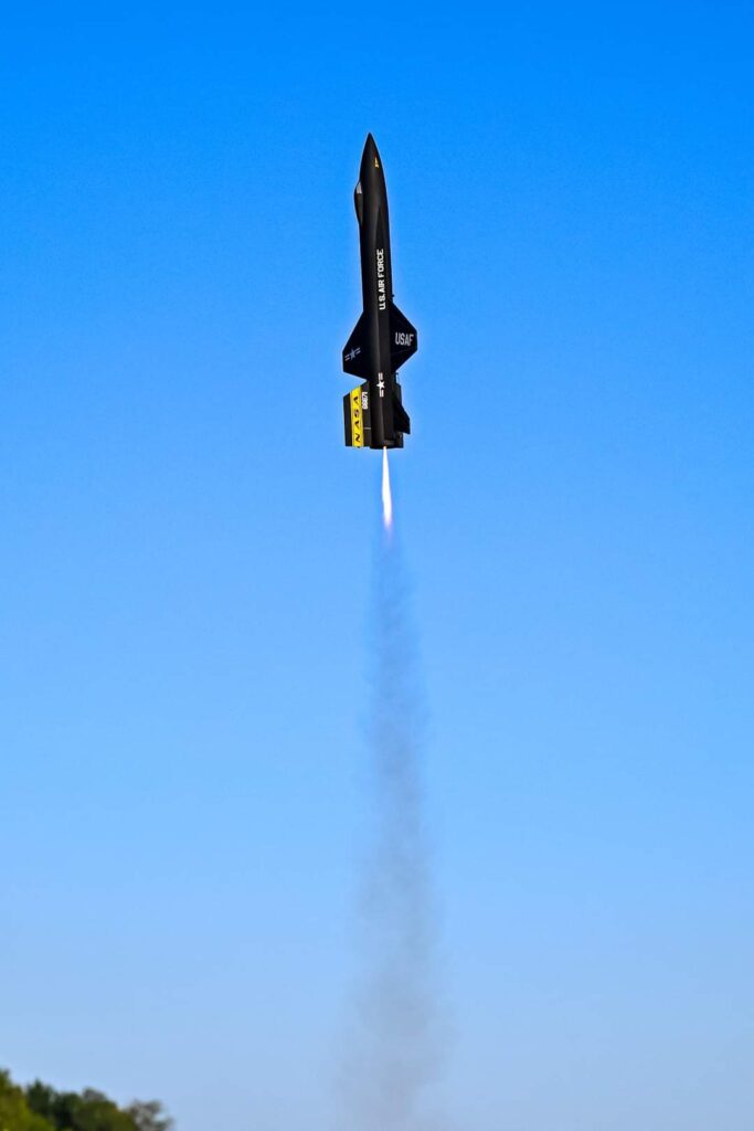
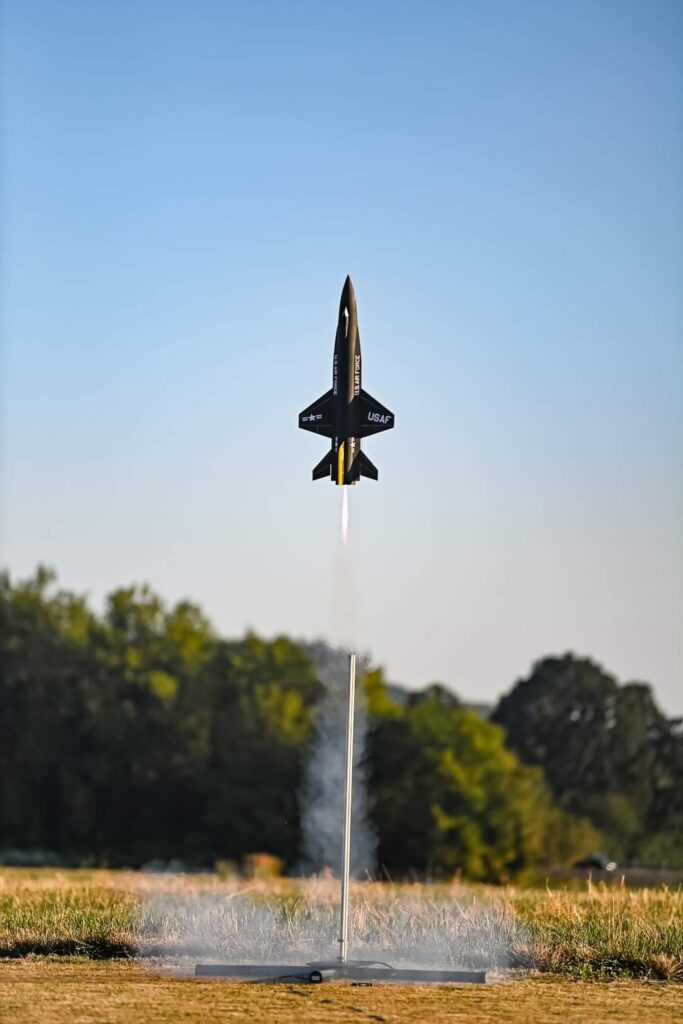
None of the three airframes required any additional nose weight to balance properly, the result of good planning and simulation. Ready to fly weights were 7.5 oz with the loaded motor and battery installed ready to fly. This model boosts to right around 400 ft at a speed that does not overstress the foam surfaces This altitude is a good maximum to allow the pilot to maintain visual orientation of a small winged model of this size. I used a 5’ long 1010 rail for launching as it does not flex and has less drag on liftoff than a typical ¼” 6’ launch rod.
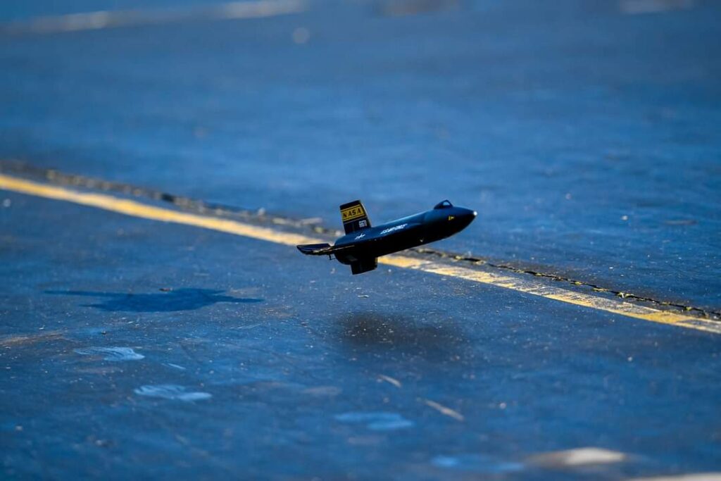
Flight tests of the models required only minimal roll and pitch trimming and all three used very similar settings. The model boosts nearly hands off and very straight with a little required pushover after burnout to horizontal to avoid a stall and before clicking in the glide trim setting. The real x-15 had a very short flight profile of no more than 10 minutes from release till landing with a very steep approach conserving energy until the threshold was made and holding a nose high flare until touchdown. The model glides quite a bit better than the real x-15 did, but it still requires the pilot to keep the flight speed up on the downwind and base turn until you are over the threshold then leveling out and letting the model settle and flaring before touchdown. Seeing the model approaching the runway looking like the real thing puts a smile on my face every time.
Completing the actual 199 flights was an intensive process that took many weeks using two reloadable motor casings and approximately 9 to 10 three packs of reloads in each flying session. Some preparation of the reloads for each session was required including peeling a thin layer off of the liner cardboard off so that they would fit into the reload casings without sticking. This is common on the smaller motors as humidity and production tolerances of the cardboard can cause variation.
I would start early each morning when winds were low and each flight session would last an hour and a half to two hours.
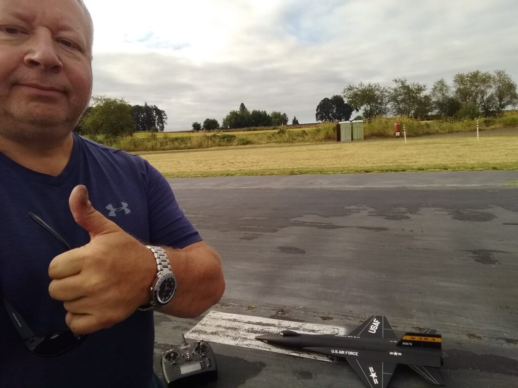
With some trepidation and my heart racing I set up for the 199th flight and took a selfie to document it. With a press of the button, the model boosted high and quick and I gracefully arced over and slowly turned down wind. At the right point I made a gentle base leg and turn to final well over the threshold and let the model settle slightly nose high with a gentle flare and a smooth touchdown right on the center line. I documented the post flight landing with a photograph much like they did for the real thing. Neither the airframes, radio equipment or motors ever had a single issue, a testament to their robustness. I had burned the equivalent of a small L motor, around 4000 newton-seconds. This was one of the most rewarding things I’ve done combining both rocketry and R/C aircraft.
The X-15 program showed that hypersonic flight and flying into space, transitioning between aerodynamic control surfaces and reaction control thrusters, maintaining proper pitch angles on on re-entry, and managing energy to a pinpoint landing on a runway every time was possible. The data gathered led directly into the space shuttle program and the choice of flight profile and design. Several of the pilots that flew the high altitude flight profiles were eventually recognized as astronauts. We all should recognize the contributions that these pioneers made to early space flight and winged vehicle reentry procedures.
I’d like to personally thank my son Max and my daughter Olivia for many trips to the flying Field, providing launch assistance and taking flight videos and to Jim Wilkerson for coming over to my club and getting excellent flight and landing photographs.
Here is a video of the 199th flight, https://youtu.be/dUNXKHmL1QA
For those R/C pilots comfortable with flying a fixed wing aileron-controlled plane flying at around 60mph, I do make a 1/21 scale R/C X-15 rocket glider kit available at dynasoarrocketry.com This kit uses the same templates and materials I used to build the models flown for this article.
Michelle Evans who wrote an excellent book on the X-15 program was nice enough to feature my exploits on her modeling page, there is also links to a lot of X-15 information, some of her talk videos and her book.
http://www.mach25media.com/models.html