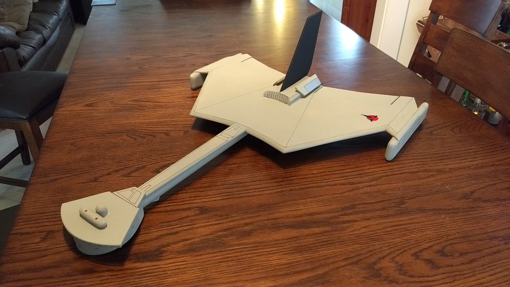
The Battlecruiser RC Rocket glider kit. It comes with white tubing for the body and Model Plane Foam (MPF) wing and tail surfaces. Construction follows typical foam parkjet construction. You will need two 8-11 gram type servos, a receiver, and a small 500mah single cell lipo battery. You will need a transmitter with delta or elevon mixing. You will need foam safe CA+ and 3m-77 spray contact adhesive for assembly. Please refer to the General instructions for all kits tab above, then read these instructions completely before starting assembly. Wingspan 24″, length 30″, weight 11 oz rtf.
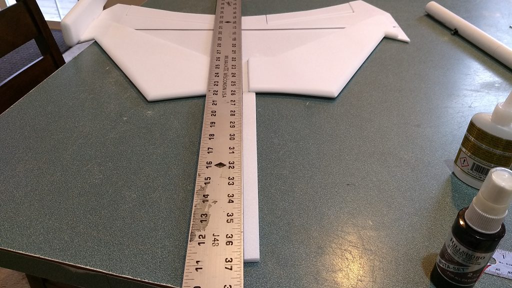
CG location for rocket flight: 8.25” forward of the rear end of the body tube. This should be right about at the fold joint in the top of the wing. (If you are building this to fly with an electric motor, your CG should be 8.5″ forward of the rear end of the body tube.)
Welcome to the world of rocket boosted radio control gliders. This is not a model for a novice RC pilot, but anyone who is comfortable with RC flying of a medium speed model should be fine. Read through the instructions, look at the photos and be sure you understand the step before commiting to cutting or glue.
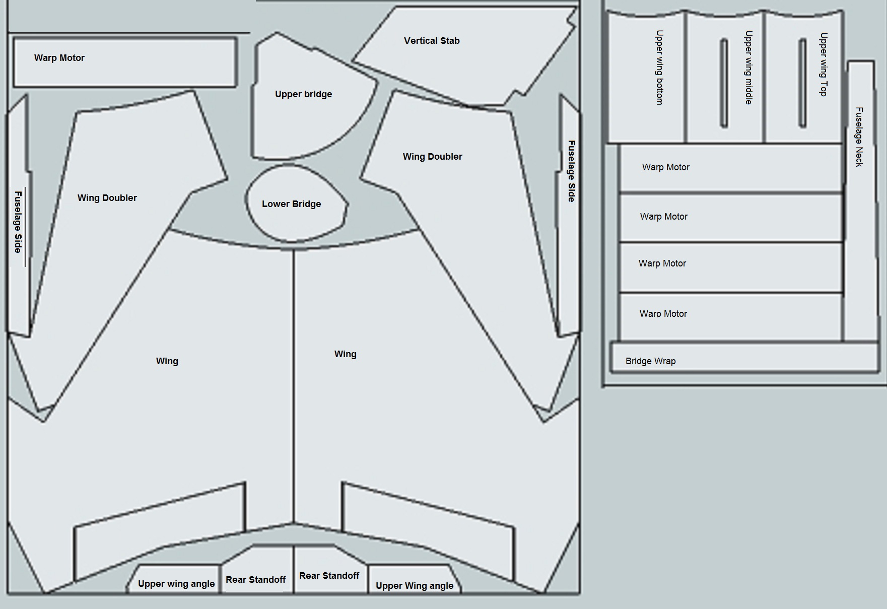
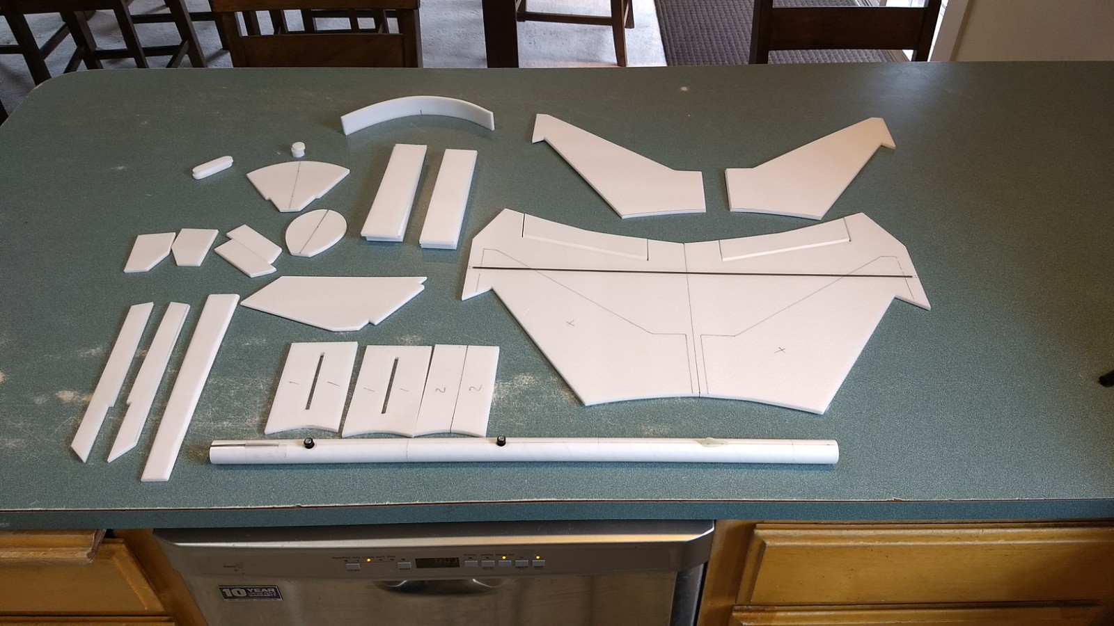
Identify all pieces, the kit should contain:
Foam Pieces:
1 wing taped together
2 wing doublers
6 Warp Motor pods
3 bridge disks
2 2″x1/2″ rounded bridge details
3 wing top pieces(two slotted, one not)
2 angle pieces for the wing top
1 bridge top
2 bridge bottom
1 bridge wrap
1 fuselage neck
2 side fuse pieces
2 rear standoff pieces
1 vertical stabilizer
Other pieces:
2 control horns
2 pushrods
1 body tube assembly
1 styrene lower plate.
Velcro(for battery and rx/bec attachment)
3M blenderm tape
Decals
Lead weight
Spare foam (for testing paint, glue, and sanding the edges to see how it behaves)
Notes before starting:
Since these parts are laser cut, there is some undercutting of the foam edges and slight flashing where the parts are cut/broken out of the sheet before kitting. Carefully take a good sanding block and gently dress up the edges square and remove the flashing before you start. You don’t want to remove a lot of material just clean them up. In addition, you may use 220-320 grit sandpaper and a sanding block to round the edges of the foam on the vertical stab and fuselage neck, and to lightly break the edges of the fuselage sides, angle plates and rear skids. It just makes them look a bit nicer. Do any sanding before assembly or as suggested in the instructions. NOTE***The foam has a smoother side and a rougher side. I’ve created the wing so that the smoother side is up, look at the foam pieces as you build and try to orient your parts so that the smooth side is exposed or up and you will wind up with a more consistent finish when you paint.
Assembly:
- Look at all parts and understand what pieces go where. There are a few pieces that are laminated together before assembly. Those are laminated with 3m-77 spray. You apply this lightly to both sides let dry for 1-2 minutes till tacky then press together. Be sure not to spray too close to the foam or it can cause some melting. If you get any overspray on foam you don’t want glued CA accellerator typically will soften the adhesive and you can wipe it off with a paper towel. The model was designed to use foam safe CA+ glue and accellerator(I use bob smith brand) and 3m-77 spray adhesive only. If the instructions say “glue” that assumes using foam safe CA+ the 3m-77 will only be used for specific steps.
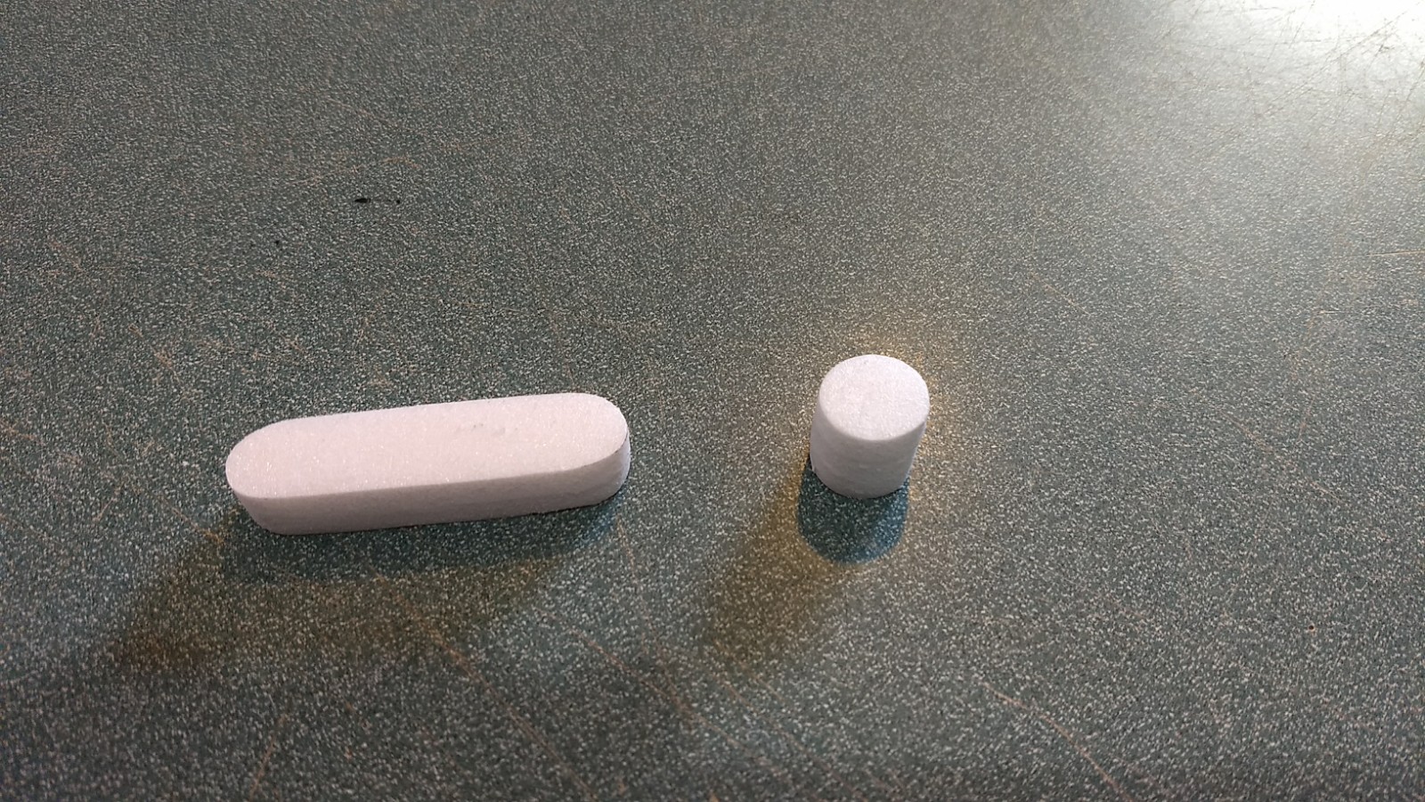
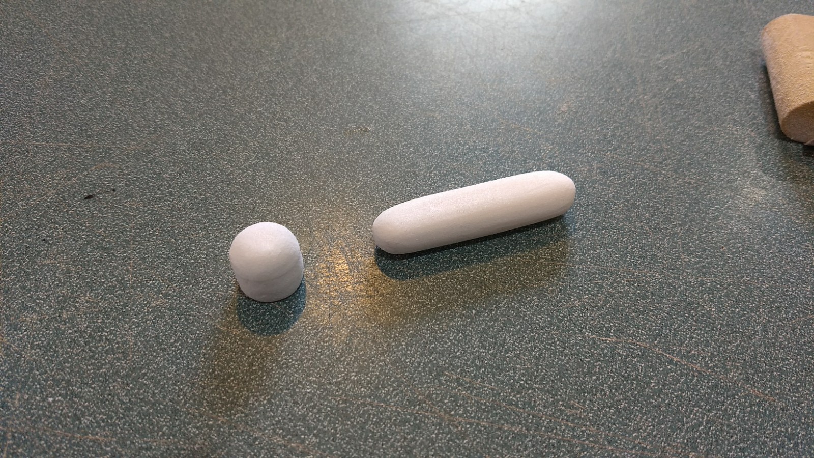
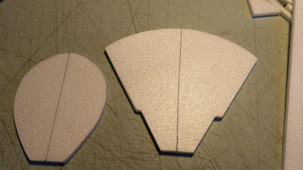
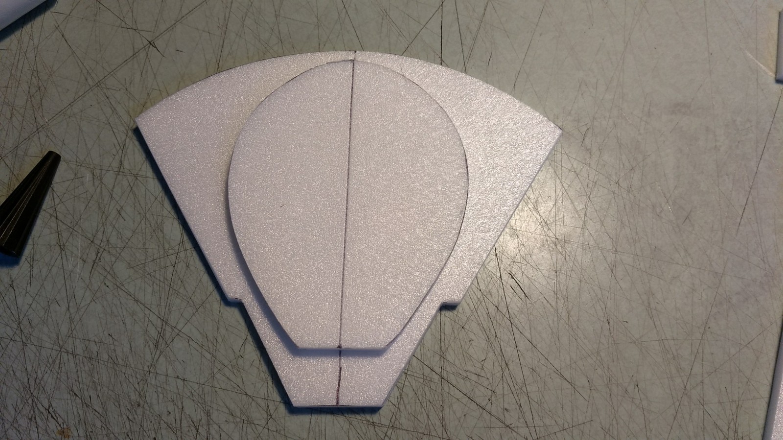
- Glue the three circles together for the bridge detail. Glue the two round ended 2″ by 1/2″ bridge detals together. Sand the top of the circle stack round and all sides of the long bridge detail piece and set them aside for later.
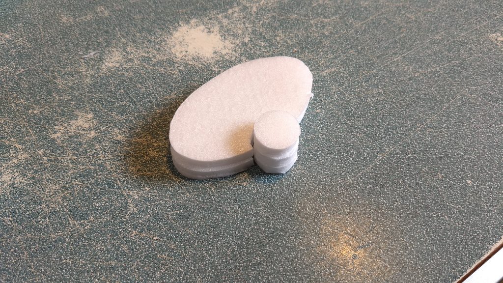
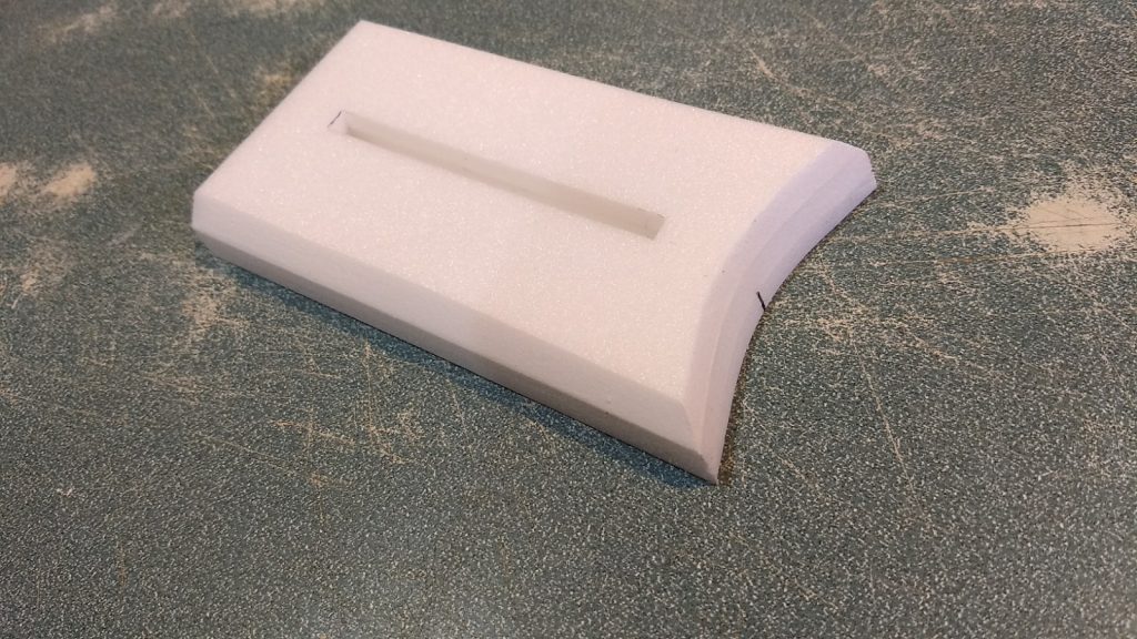
- You will then glue the three pieces that form the upper wing assembly that the vertical stab goes into. Two pieces are slotted, one is not, the unslotted portion is the bottom, the slotted pieces go on top. Use the 3m-77 spray to laminate two pieces together and then do the final piece to this assembly. Using a scrap of foam make sure the top two pieces with the slot are aligned so when the vertical stab is inserted it is vertical.
- Lightly sand the three straight sides so that they are smooth.
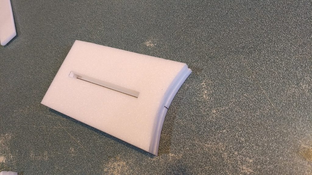
- Insert the vertical stab temporarily and mark where the front of the stab hits the upper wing stack. Make a mark on the top plate then sand or cut with an exacto the front curved portion of the stack back at an angle to the line you just made. This is just a decorative slope.
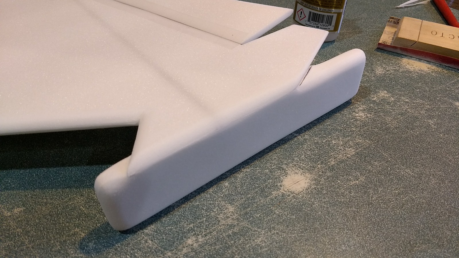
- Sand the two top side corners of this assembly at a 45 degree angle that is approx 1/4″ wide.
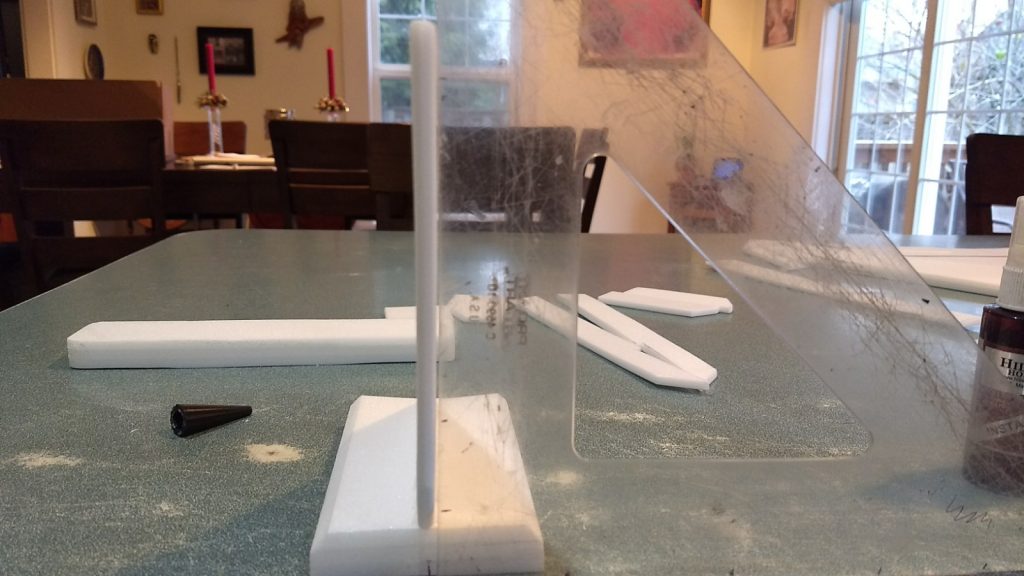
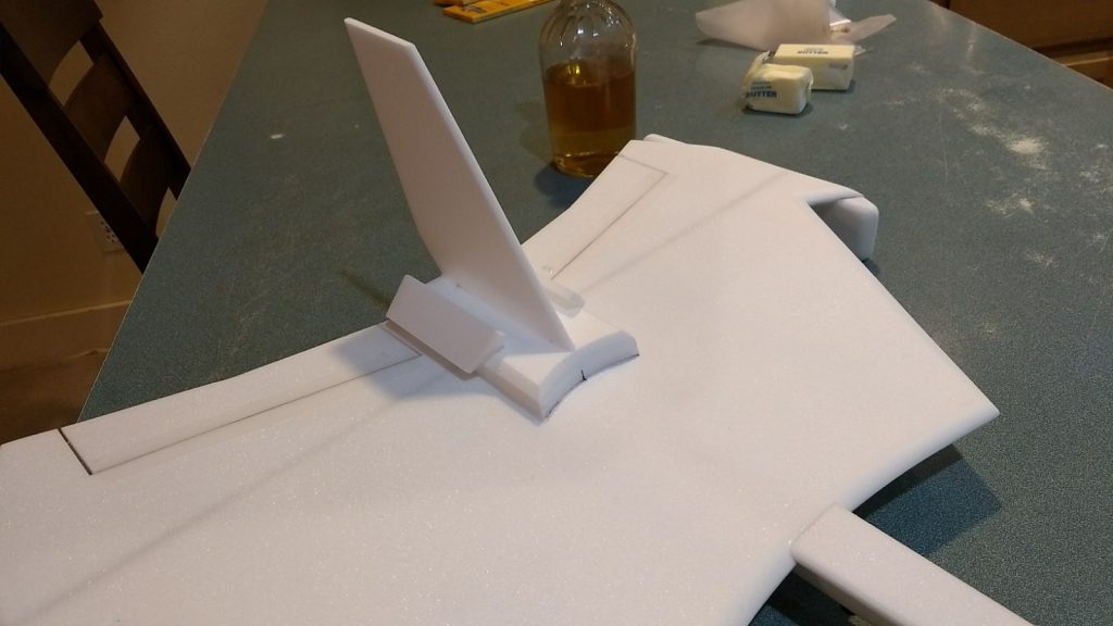
- Sand the vertical stab edges round. Make sure the vertical stab is flat, if there is any curve to the foam, gently bend it with your hands in the opposite direction to straighten it, and then glue it into the slot in the upper wing assembly making sure it is vertical.
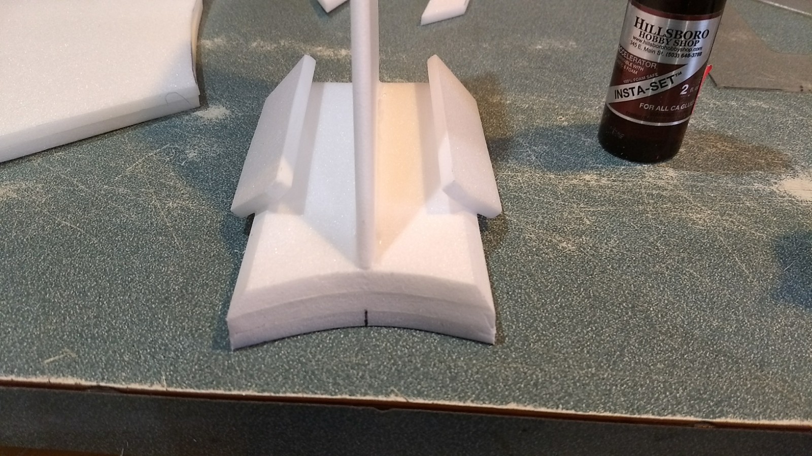
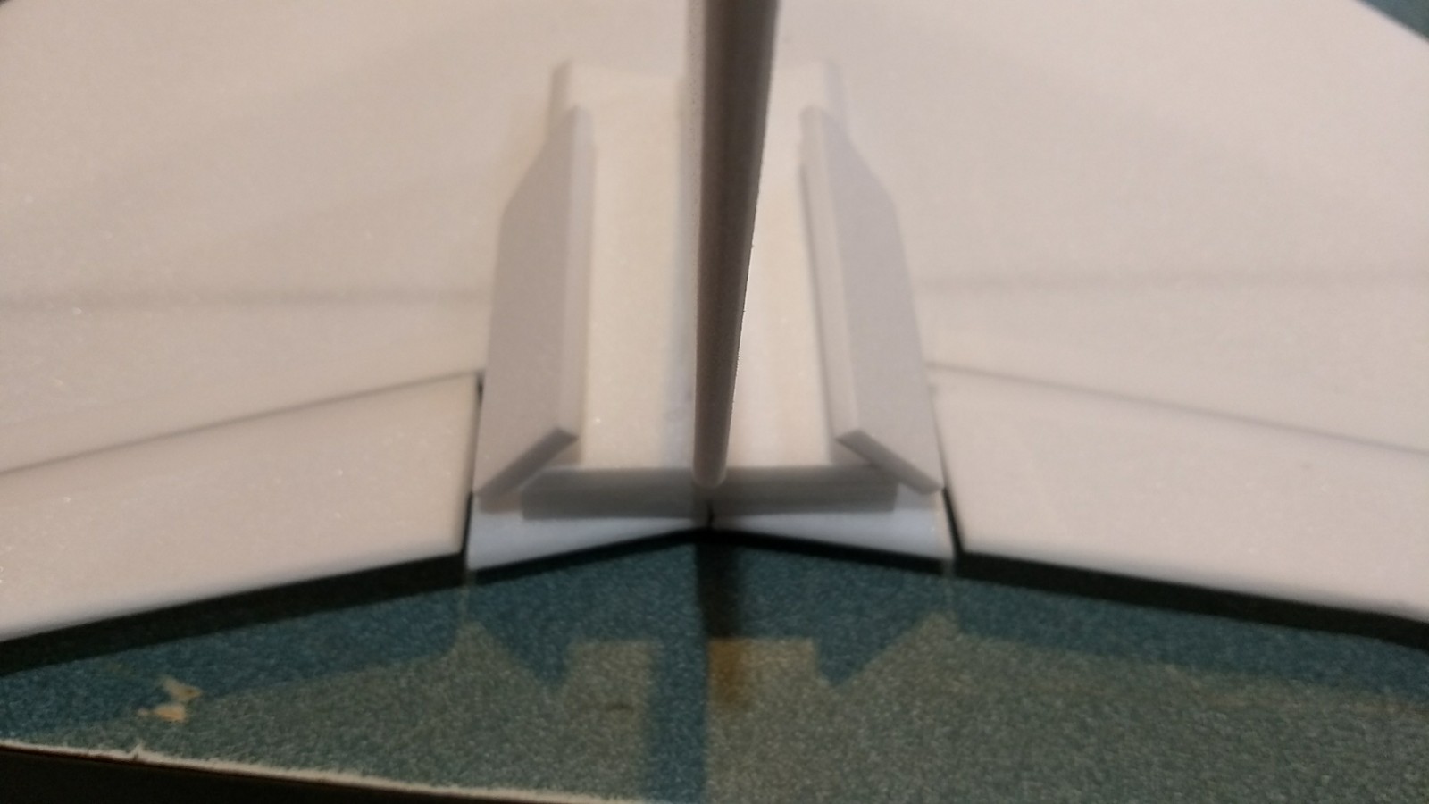
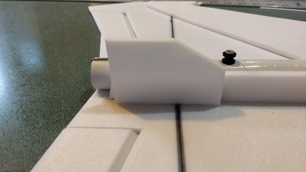
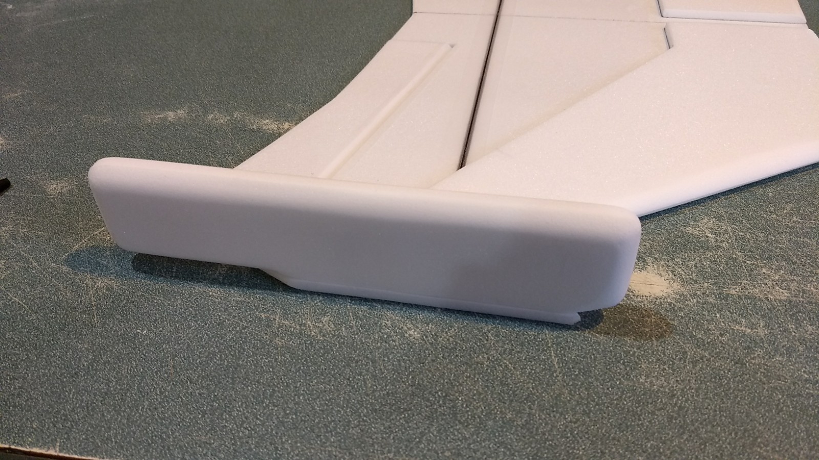
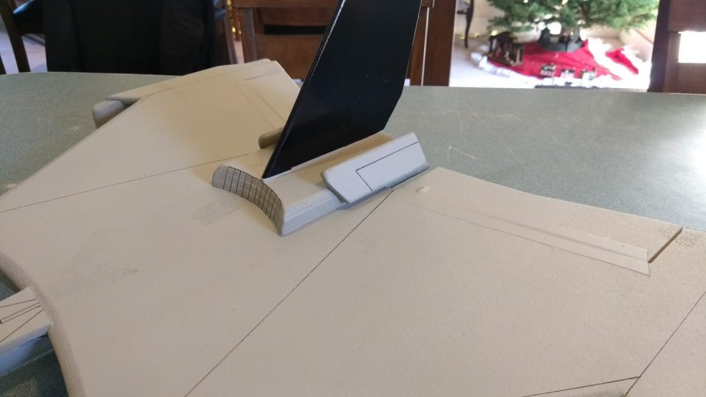
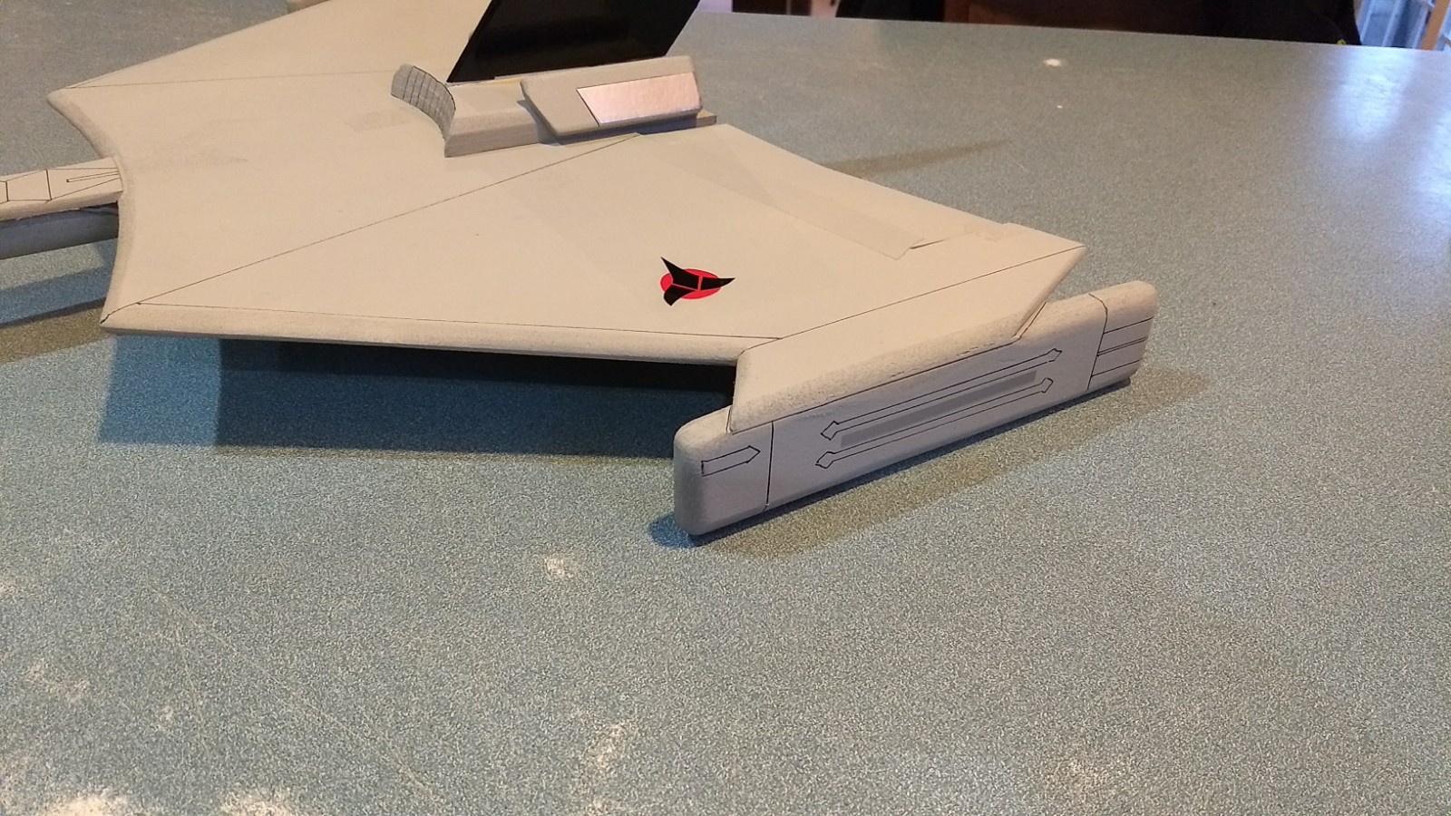
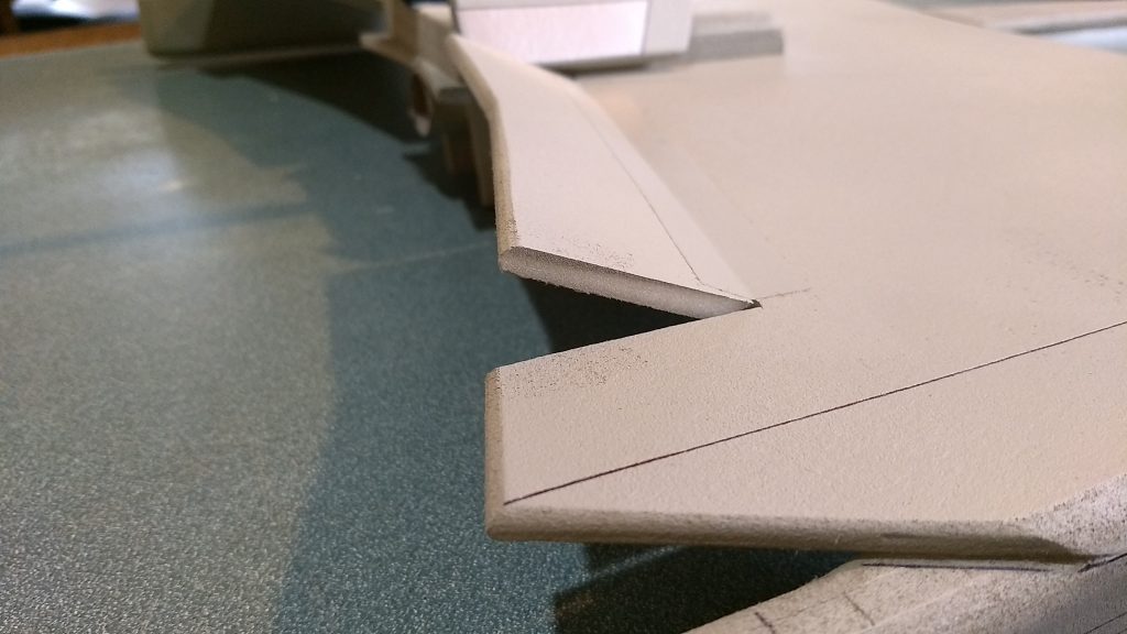
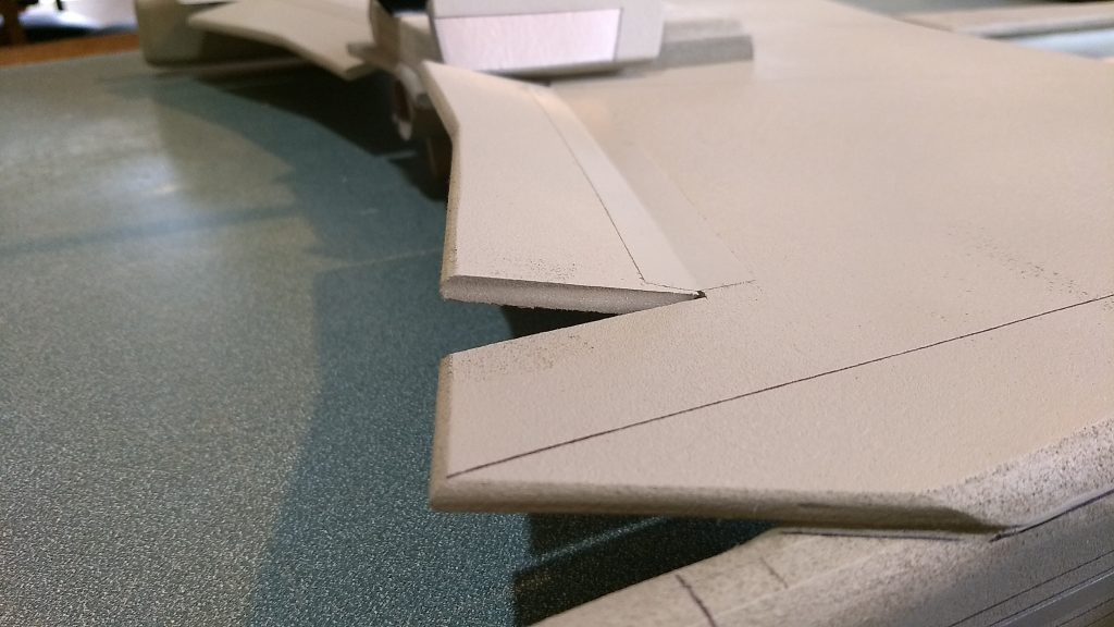
- Sand the two small side plate edges slightly to break the corners then glue them even with the rear of the stack one on each side against the angle you sanded earlier. The angle pieces should not stick out very far from the sides of the stack at the bottom or they will interfere with the elevons. See the picture. If you set the assembly on a table, and you look from the side, the bottom of the angle plates should be at least 1/4″ above the surface of the table and only stick out about 1/4″ on each side compared to the upper wing base.
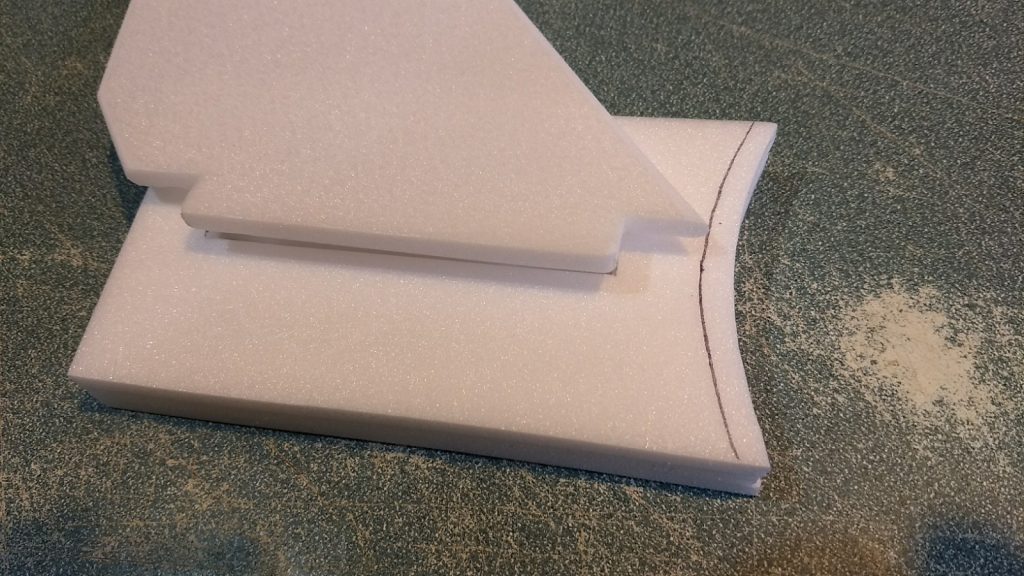
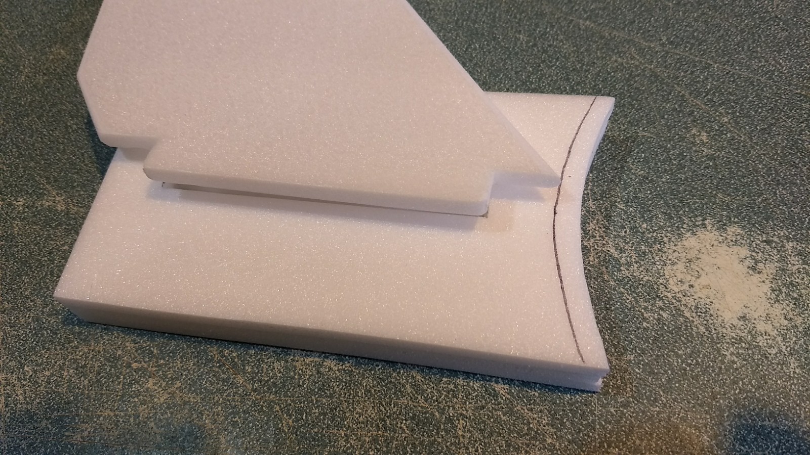
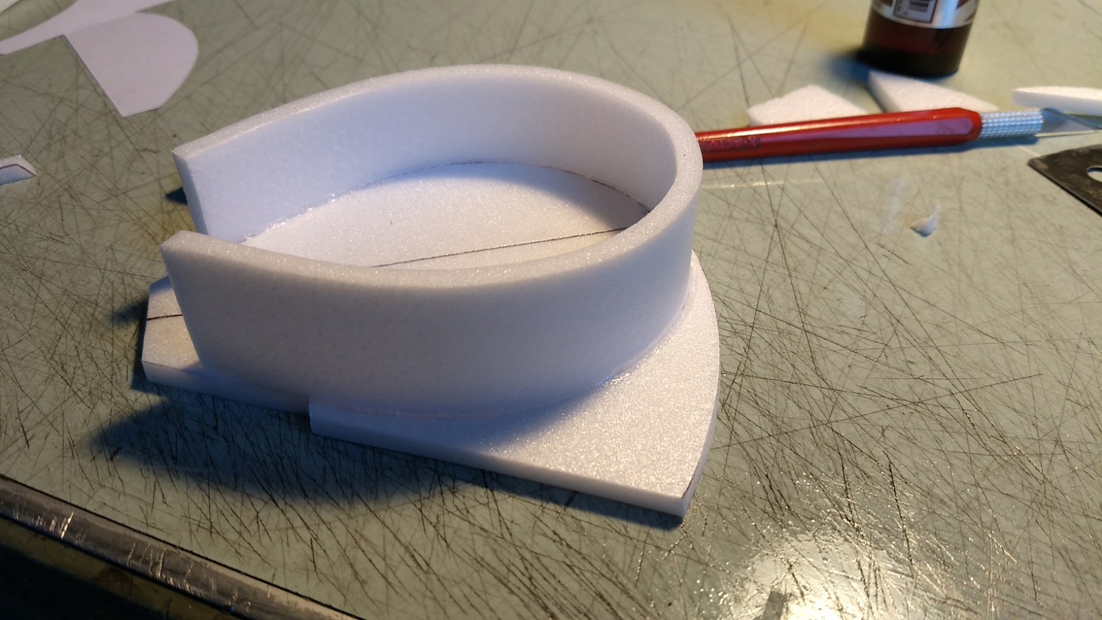
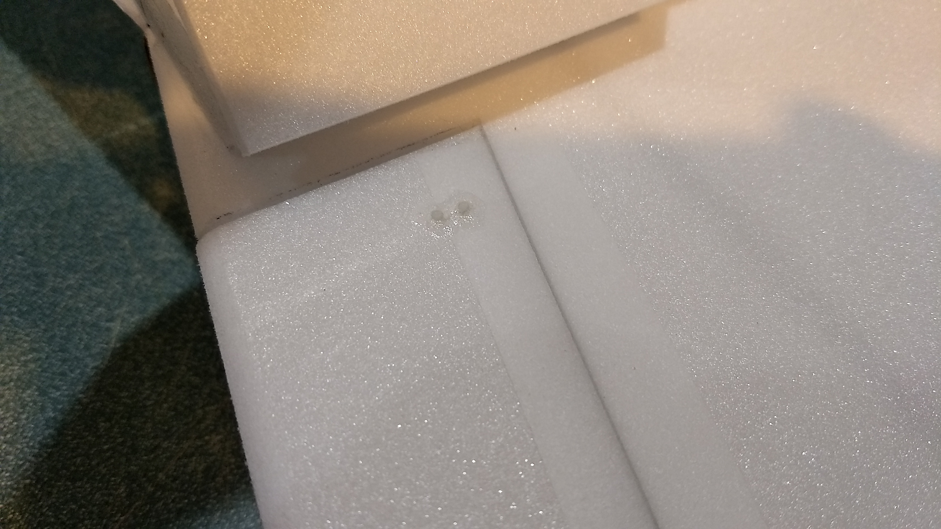
- Find the upper and lower bridge plates. Measure and make a center line on each piece. using the center line as a guide, glue the smaller bottom piece to the larger top piece leaving a 1/4″ gap from the front of the top piece. You need this gap to leave room for the side bridge strip/wrap which will be installed next.
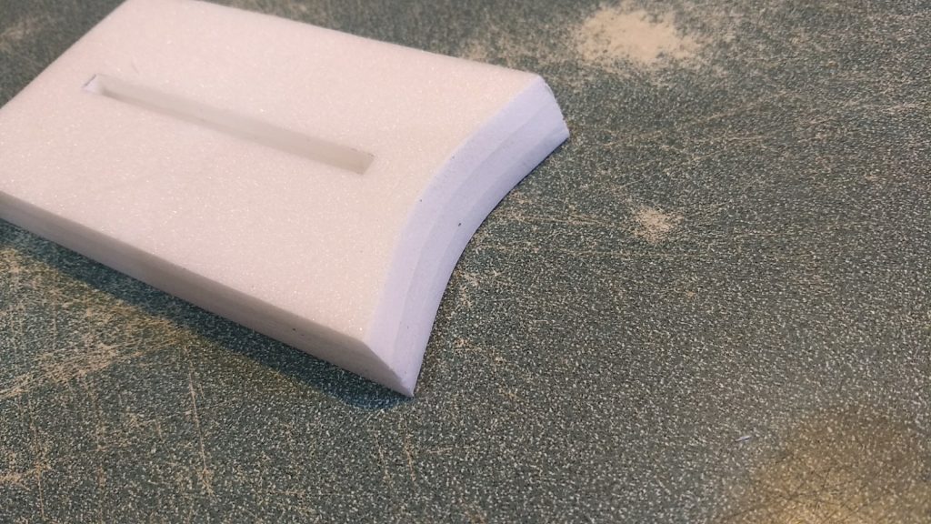
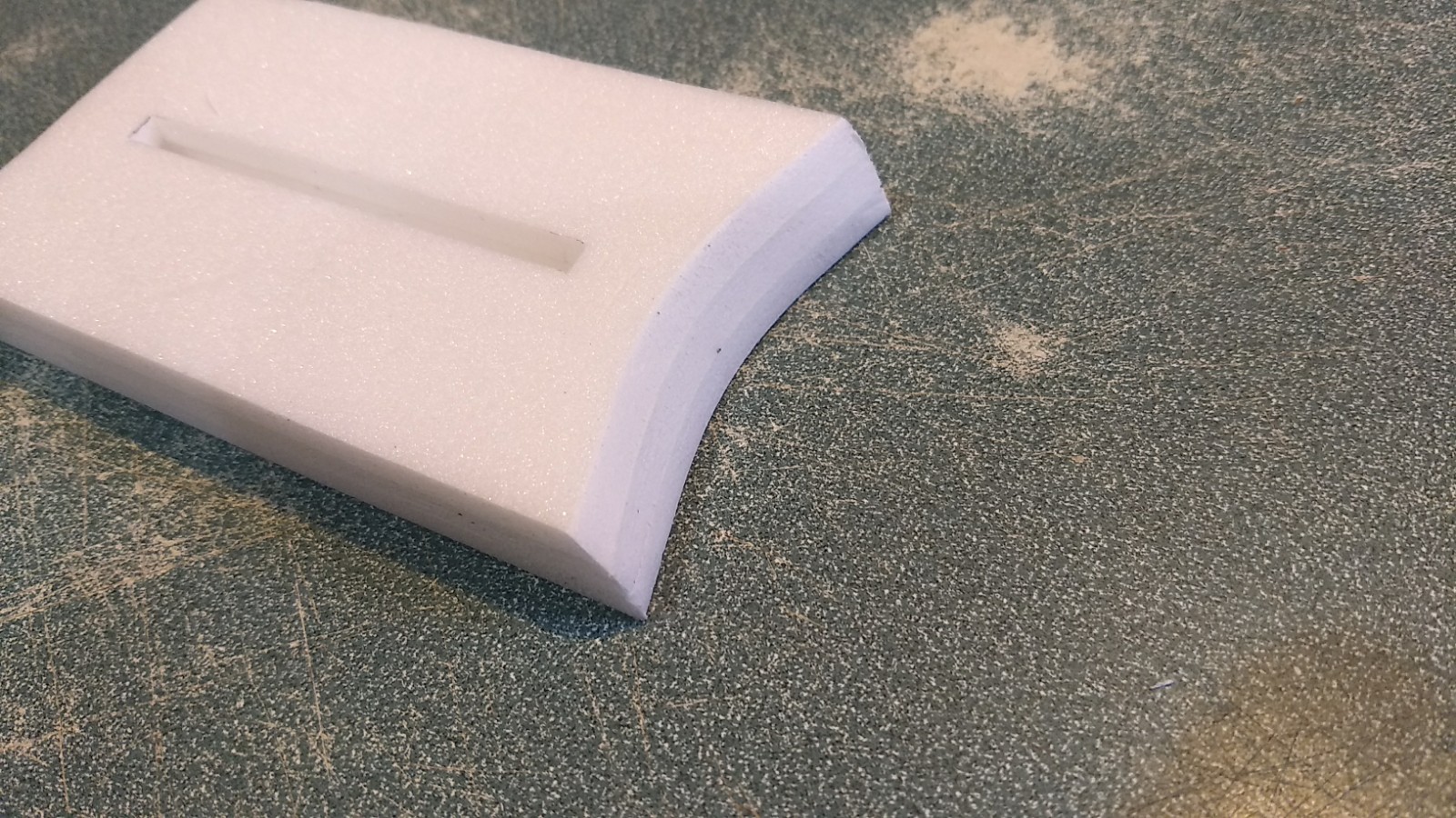
- Find the straight strip that will wrap around the bridge. Find the center of this strip and make a mark. Use your hands to form this strip into a curve by gently bending between your thumbs. Using the center mark as a guide, line it up with the center line on the front of the bridge top/bottom assembly and wrap it around both sides. The ends should be even with each other. If not, adjust your center line on the wrap so that the ends will be even when glued in place. Apply CA+ and and glue it in place, curving it as you go. Try to make sure the sides are straight up and down as you glue it down. Hold it till it sets or have someone use accelerator to set the glue. Set the assembly aside.
- Motor pods, there are six long rounded rectangles that form the warp pods. Using the 3m-77 spray adhesive you will laminate 3 pieces together to form the warp pods. You spray the 3m-77 on both pieces, let dry for 1-2 minutes then press them together. You cannot separate them after touching them together so make sure you do this carefully. If there is any warp in the pieces try to reverse the pieces before gluing so that the warp will be removed. Then spray and laminate the third piece together with the two you just laminated. You want these to be as flat as possible. Sand the edges even and flat. Repeat for the other pod.
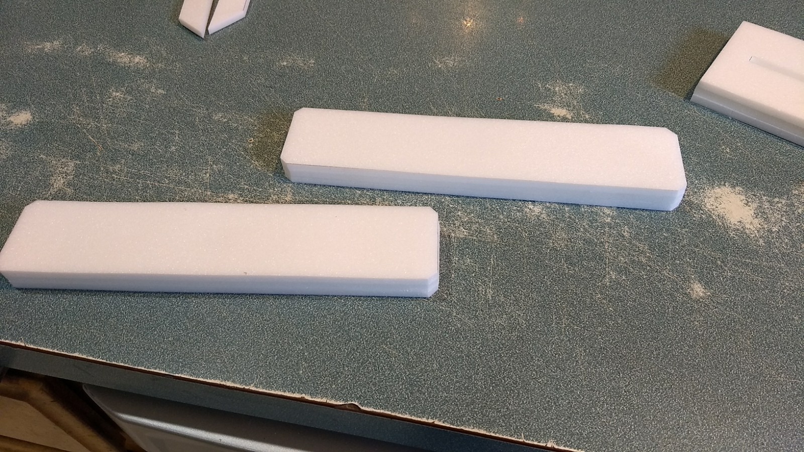
- You will then mark the pieces so you know where to sand them round. Each warp pod should be placed so that the outside is even with the wingtip end, and the warp pod sticks out 1/2″ to 3/4″ forward of the outboard wingtip at the front. Using a sharpie, mark where the warp pod will be glued. This part will stay flat and unsanded. Carefully round all other edges, you may want to use an exacto and a straight edge to trim the corners that will be sanded at a 45 degree angle lightly to make the sanding go faster. You will need to do the same thing for the other warp pod on the other side. Set these aside. Note you have to make a left and right warp pod!
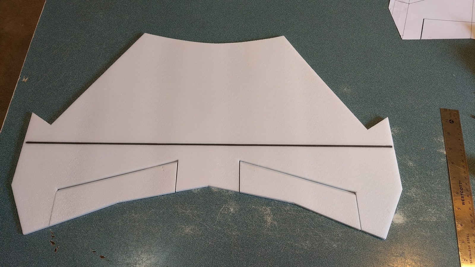
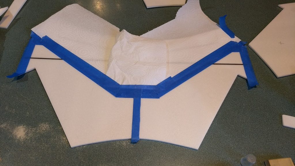
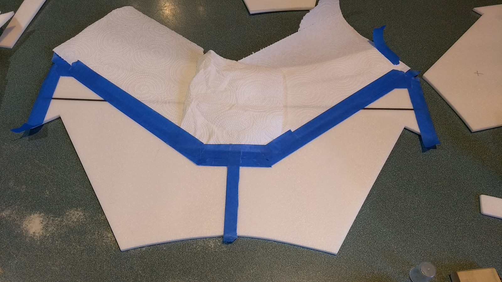
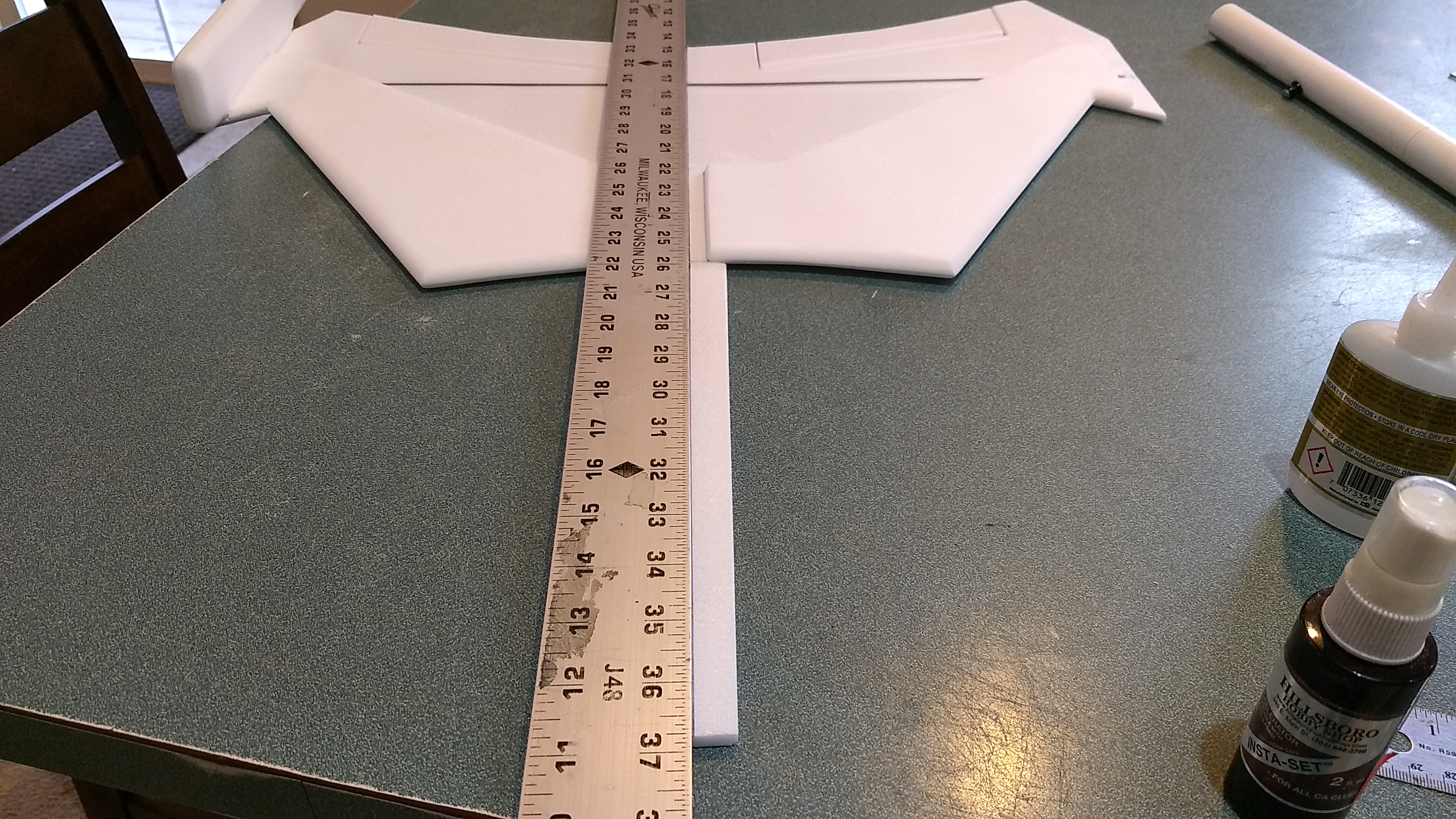
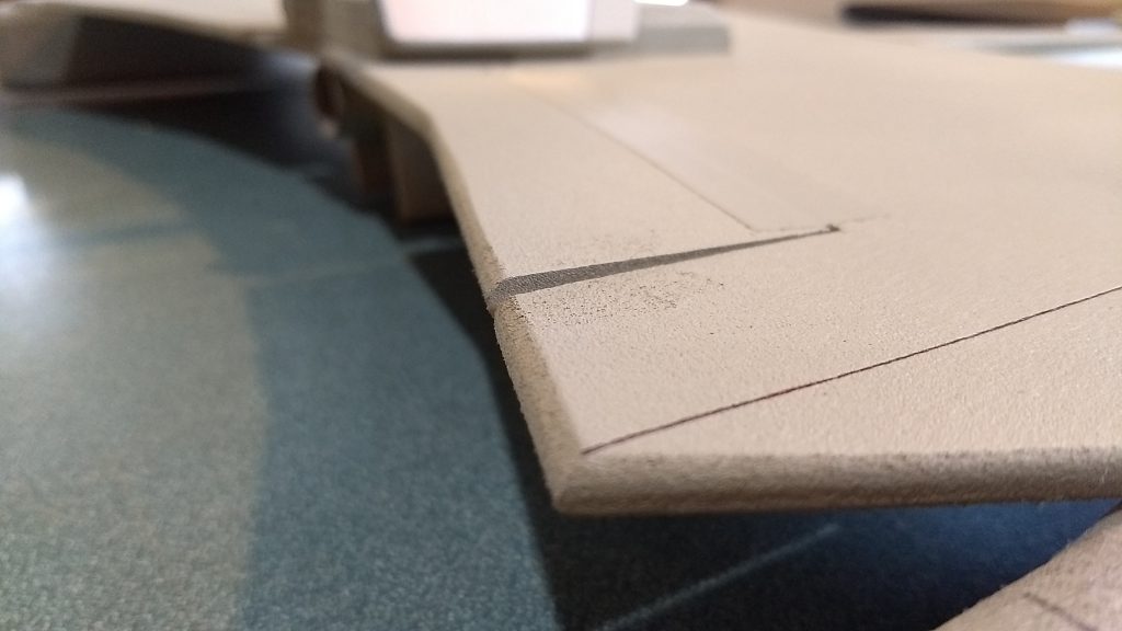
- Unfold the wing and glue the joint using foam safe CA+. flip the wing over. The side with the spar is the bottom and will be up for the next steps. Measure accross the front of the wingtip and find the center of the wing, do the same near the rear of the wingtips and draw a light centerline down the middle of the wing. I used a fine sharpie. This will be used for alignment during assembly.
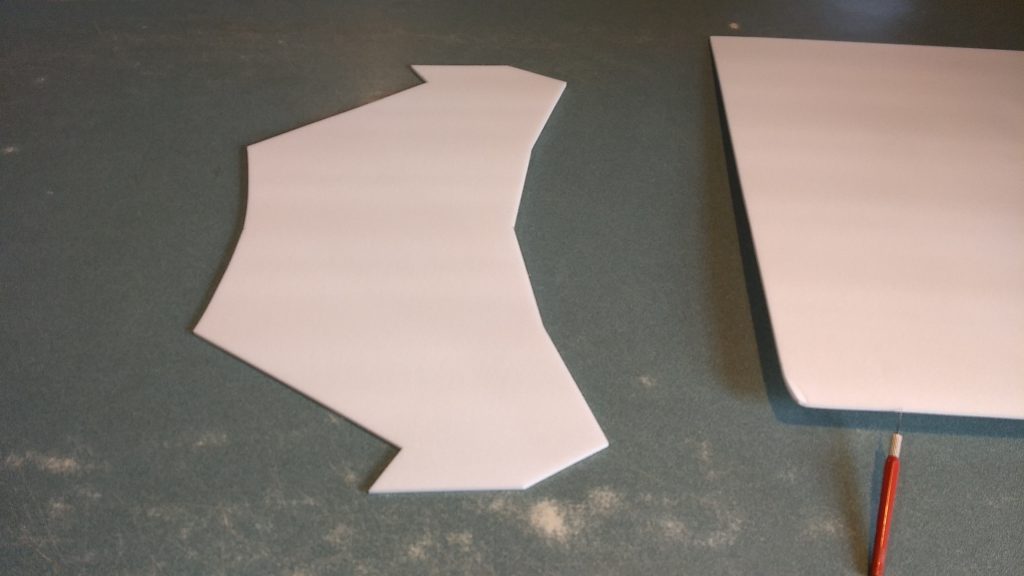
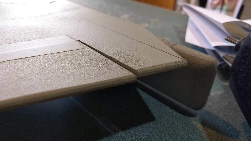
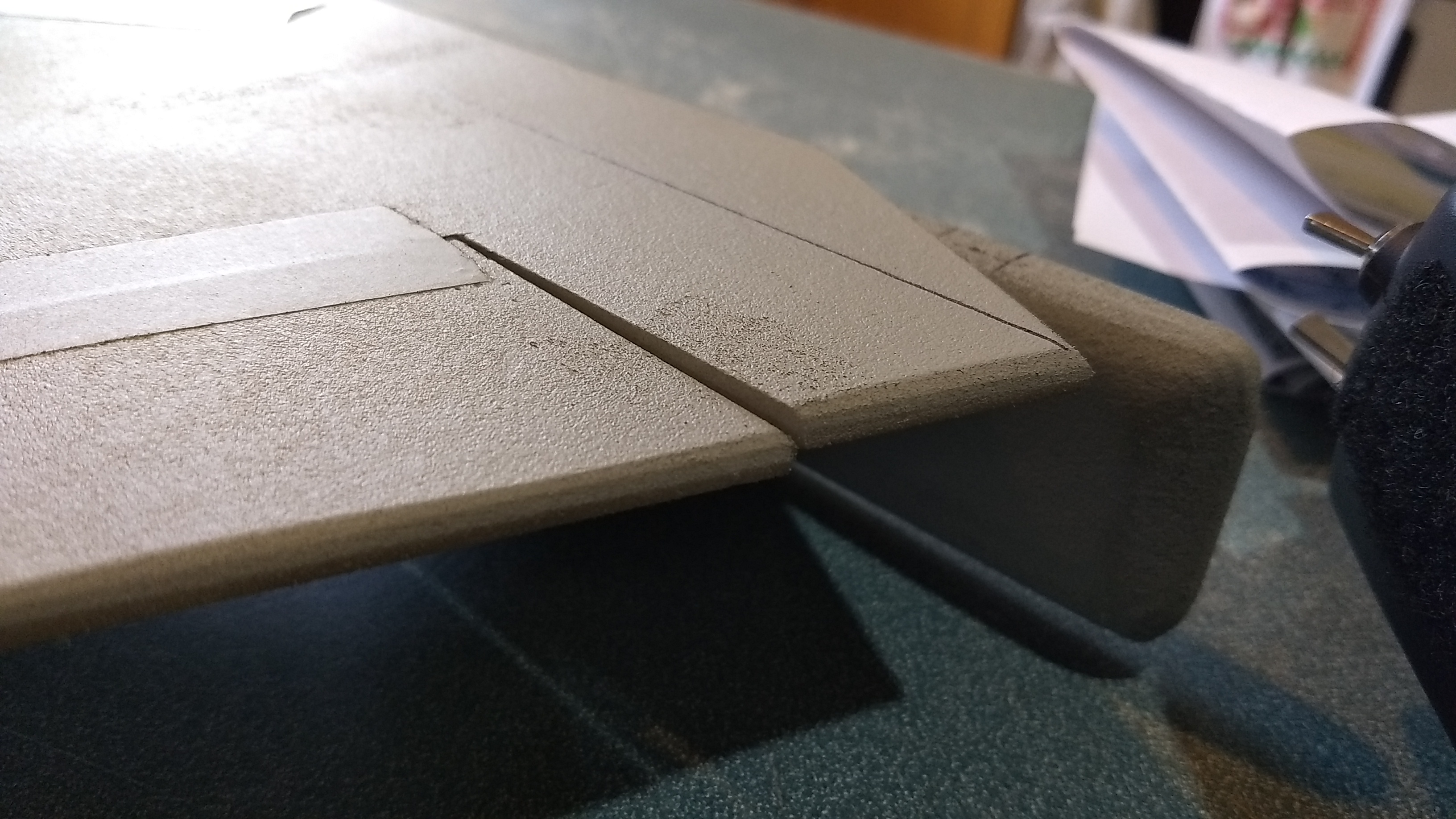
- Locate the wing doublers. One will be glued to each side of the wing, the leading edges will be aligned, note there should be an approx 3/4″ ” gap between the two sheets in the middle for the body tube. The doublers don’t go out to the wingtips so that they make a step to help align the warp pods when gluing. Using masking tape and some wax paper or paper towels, mask off the areas of the wing that are not covered by the doublers. Using 3m-77 spray, spray the doublers and the wing and remove the masking. Note when you spray the doublers there needs to be a right and left side so make sure you spray glue on the correct side to make a pair. Apply each wing doubler in place taking care to keep it aligned with the leading edge of the wing. Once they are installed you may sand the leading and trailing edges round if desired. Do not round the wingtips at this time. Lay the wing upside down on a table so that the spar and doublers are up.
- Mark a line down the center of the bottom of the neck piece. This will be used for aligning it with the wing centerline. If you sanded the leading edge of the wing round, you will need to sand the rear of the neck piece at an angle so that it will make good contact with the wing. Place a piece of waxed paper under the wing, and using a straight edge make sure the neck makes good contact with the wing and that it will be straight with the centerline of the wing. Making sure the wax paper is under the glue joint, glue the neck to the wing keeping it straight. It is very fragile at this point till you glue the body tube down so handle carefully.
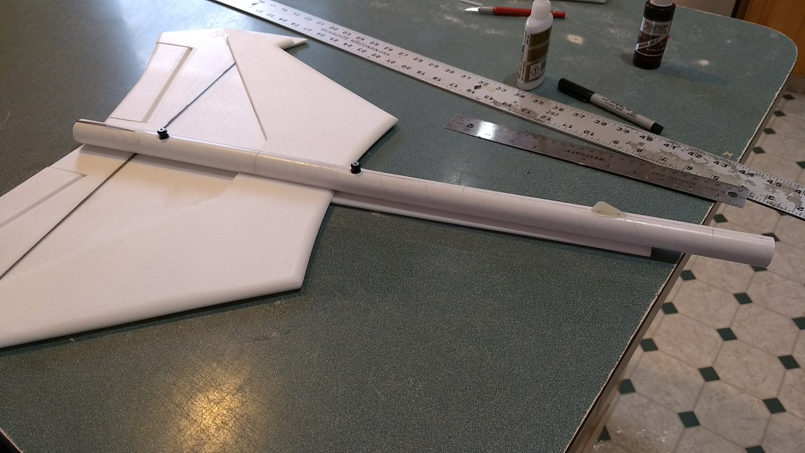
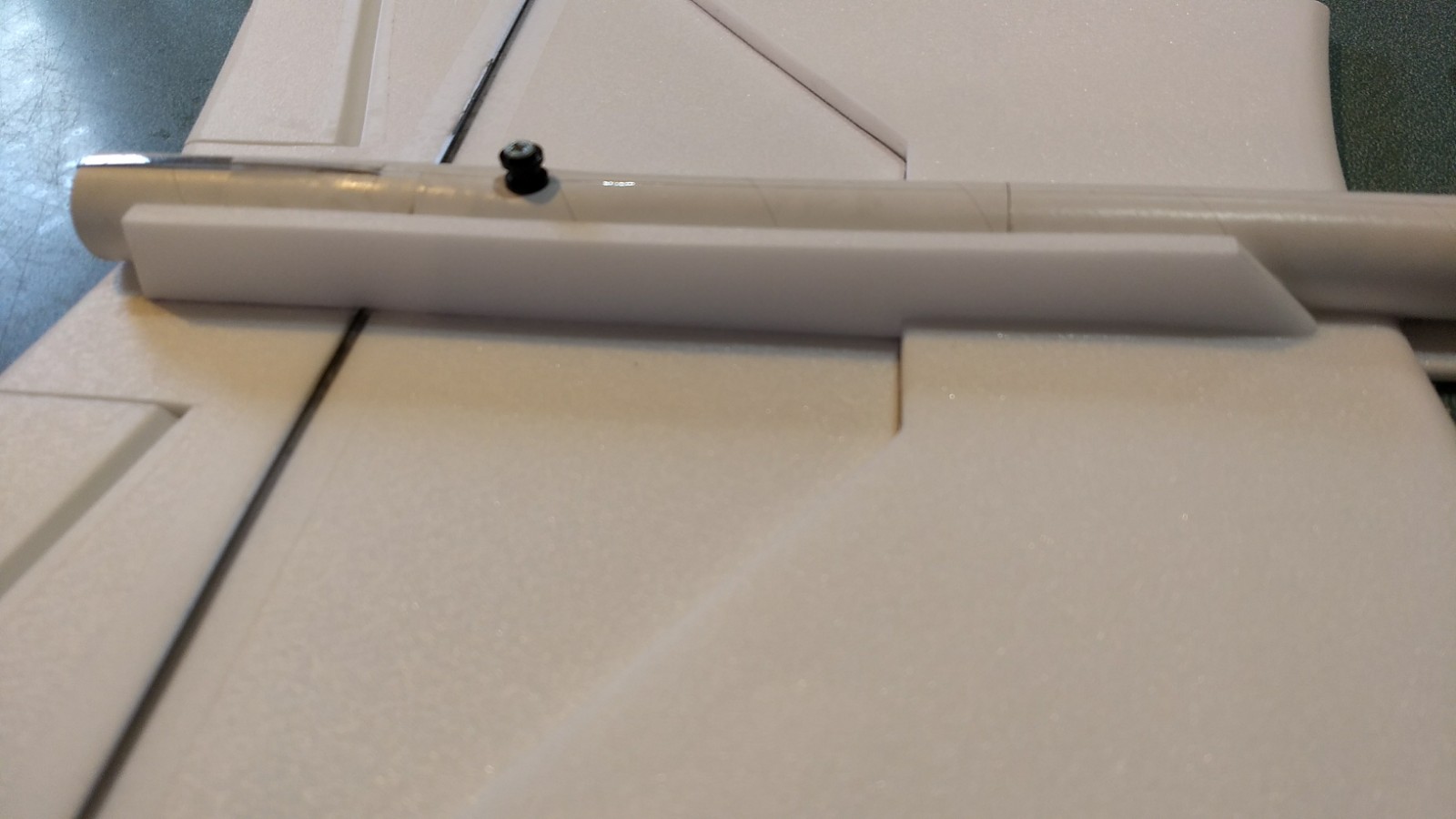
- Test fit, then glue the body tube assembly so that it is even with the rear of the wing, makes solid contact with the wing and neck and is level and straight. There is a line on the body tube and a line on the wing/neck to help make sure things are lined up. Make sure the motor hook is to the rear and that the rail buttons and skid are pointing straight up. It may help to trim the inside edges of the wing doublers at a slight angle to allow the body tube to sit flush with the wing. Make sure the neck is centered on the body tube at the front. The tube will stick past the end of the neck, that’s ok the bridge will glue to the tube later.
- Glue a fuselage side plate on each side of the body tube so the step is on the doubler. This helps provide some extra gluing surface for the wing/body tube joint.
- Glue the rear plates against each side of the fuselage plate toward the rear of the model with the angle facing forward. These help keep the model from sagging in the middle as it lands. Glue them just forward of the rear of the fuselage side pieces.
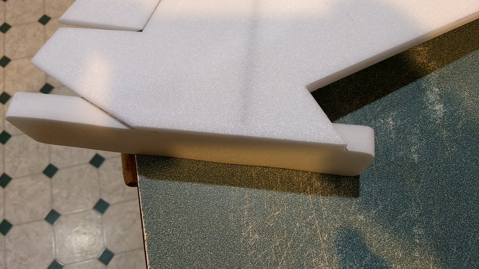
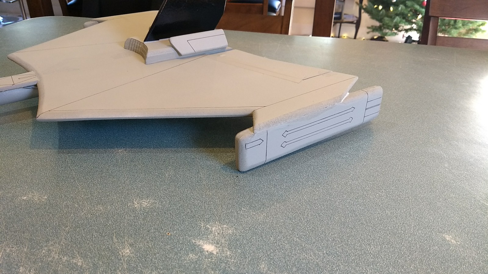
- The warp pod assemblies glue on the wingtip against the wing doubler. Make sure they make full contact and are straight compared to the fuselage tube. Glue a pod on each side.
- Flip over the wing and sand the wingtip round to blend it into the warp pod, then lay the wing upside down again.
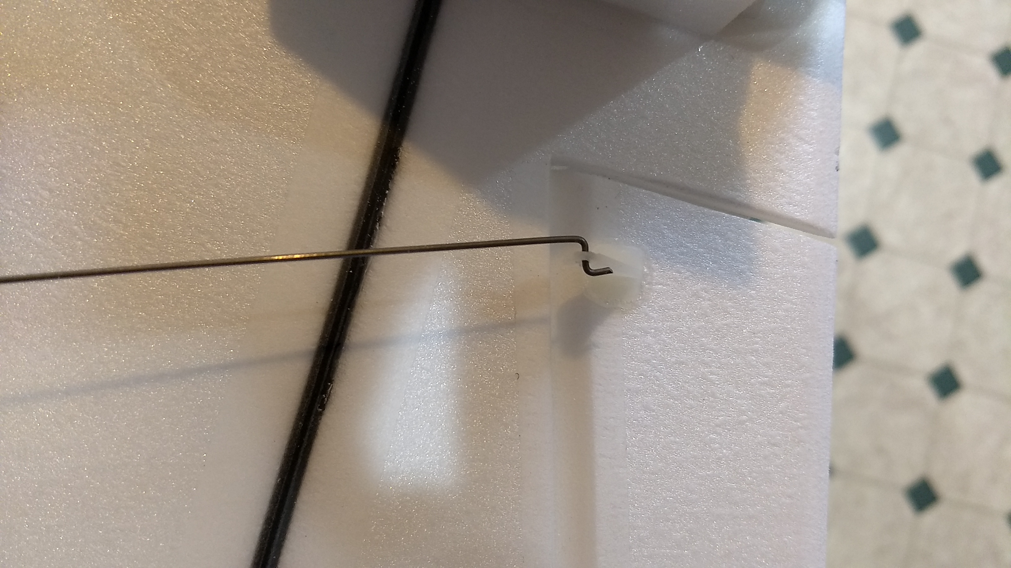
- Apply CA+ to each of the control horns and press them in place in the bottom of each control surface into the pre-made holes. Note the control pushrods go on the inside of each control horn nearest the body tube The holes in the horn face forward and the pushrod should be closest to the body tube. Apply a fillet around the control horn and the top of the prongs on the top of the wing.
- At this time it is easier to go to radio installation since the wing can sit flat on the table while you install the radio gear.
Radio Installation
Note: Your radio needs to be configured for Delta mixing, this means that the servo arms will move the same direction during elevator stick movement and opposite for aileron stick movement. Connect your servos to the receiver one in the aileron connection and one on the elevator connection and apply power. Use a servo arm at least 9/16” long and with holes small enough that there won’t be slop with the pushrod wire when installed. I use the hole furthest out on the servo arm, to maximize movement. On some servos there are a long two-ended servo arm, you can use this arm and trim off one end. Zero out any trim settings on the transmitter.
- Connect a servo to each pushrod. If the pushrod is too tight, you can use twist an X-Acto knife in the servo arm hole to make it larger, but be careful and do not make it too large. Once connected, lightly tape each servo in place so that the control surfaces are centered. Flip the model right side up and look at it from the rear. Moving the transmitter stick back(up elevator) should move both elevons up. Moving the transmitter stick to the right should move the right elevon up and the left elevon down. If you can’t get the servo reversing to give you the right polarity try swapping aileron/elevator inputs to the receiver or turning the servos over and swapping the servo arms to the other side of the output shaft. If that is correct, continue.
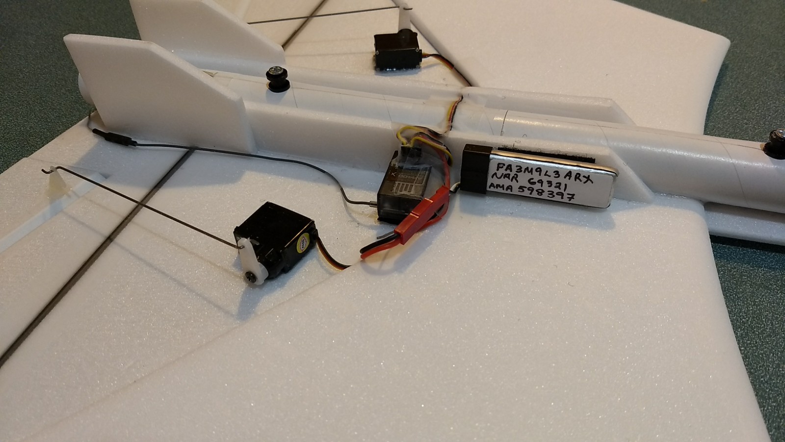
- Flip the model upside down. The servos may be attached to the model using double back servo mounting tape(not included) or by directly gluing the servo to the wing with foam safe CA+. Double back servo tape can loosen over time and with exposure to heat, I prefer to glue the servo in place. With the radio still on, put a moderate amount of glue on the servo, being careful not to get any near the output shaft, and set it in place on the model keeping the control surface centered. Do the same to the other side. Make sure the glue is set before continuing. Note** The servo electrical wire should point toward the front of the model, you want the pushrod to be perpendicular to the hinge line, the servo will be near the edge of the wing doubler. See the photo for an idea of how it should look. The servos will be 2″ to 3″ away from the fuselage. Disconnect the servos from the receiver.
- Tape the servo wires down against the step in the wing doubler using the blenderm tape.
- Decide which side the receiver and battery will be mounted on.
- One servo wire will need to be routed to the other side of the model so it can connect to the receiver.
- Make a groove in the foam fuselage sides for the servo wire and route through the groove, and against the body tube and over to the other side of the model. Tape the servo wire flat to the tube so that the launch rail won’t drag on the wire. Alternatively you can use an exacto and cut a 1/2″ by 1/8″ slot on both sides of the fuselage through the body tube and foam to pass the servo wire to the other side. You can also tuck extra wiring for both servos into this slot and then use a piece of scrap foam cut slightly oversized and pressed in place to hide the slot on both sides. If you don’t glue in the scrap foam you can remove it if you ever have to replace servo later. I’ve used both ways.
- Attach the servo wires to the receiver and make sure the controls are still working as they should.
- Using velcro attach the flight battery and receiver to the model and tape down the antenna and any extra length of servo wire and battery wire down with blenderm tape to hold it in place in an orderly fashion. I placed the battery on the side of the fuselage right next to the receiver as far forward as possible.
- Flip the model back right side up. Make sure the control surfaces are centered, use trims if needed. Now measure the control surface movement. Full elevator movement should be 3/4” in each direction, aileron movement should be 1/2″ in either direction. Since the model will be nose heavy after motor burnout, extra elevon movement helps to give sufficient authority during glide.
- If you have a flap/elevator mix you can program up elevator to a switch setting. The model needs approximately 1/16″-1/8″ of down trim for boost and 1/16″ to 1/8″ of up trim for glide. If you can’t set the up elevator trim to a switch on your radio you’ll have to manually put in boost and glide trim which is hard to do while flying the model. Lay the model upside down on a table when the radio install is complete.
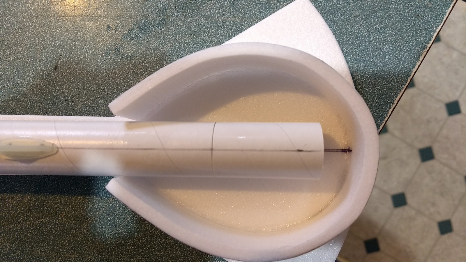
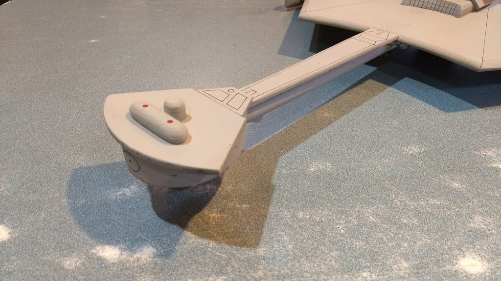
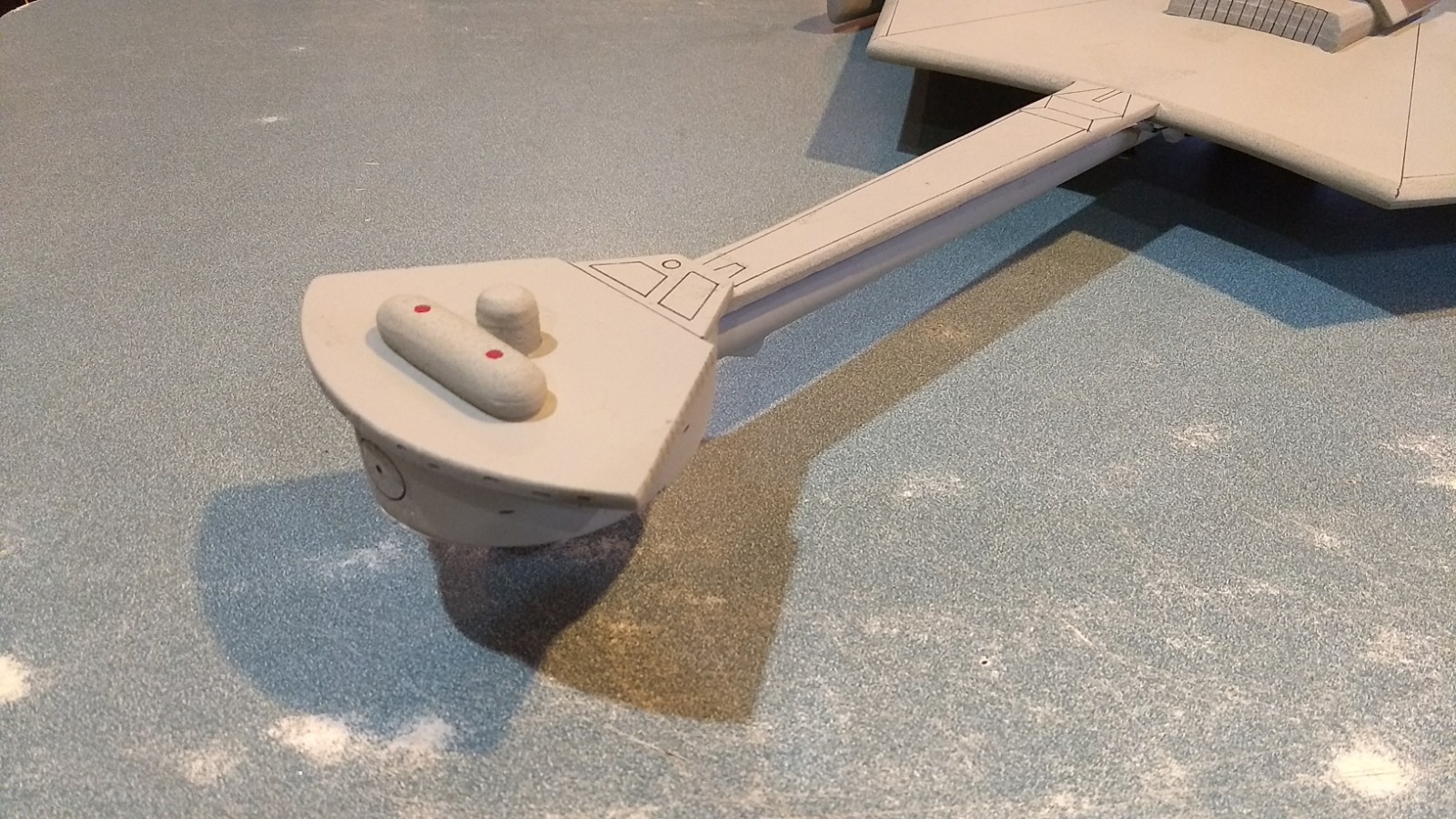
- Glue the bridge to the forward body tube. The inner bridge piece butts against the front of the neck and the top of the bridge overlaps the neck piece. When glued in place properly there will be about a 1/2″ gap from the front of the tube and the front of the bridge wrap. This gap is used to place nose weight when balancing.
- The plastic plate for the bottom of the bridge will be painted separately then taped in place for balancing. It is cut to size but differences in how you glue the bridge wrap might mean you have to trim it slightly. Once your nose weight is added as needed, you can tack glue the plate in place.
- Glue the vertical fin/upper wing assembly onto the top of the wing with the rear even with the rear of the wing. You want to make a mark on the assembly for the middle and use a straight edge to make sure you are keeping the assembly in the middle and the vertical stab exactly lined up with the body tube and bridge assembly. Make sure you are centered at the rear as well between the two elevons. Make sure the elevons clear the angled plates glued to this vertical stab assembly, if not trim the inboard ends of the elevons so that they do clear.
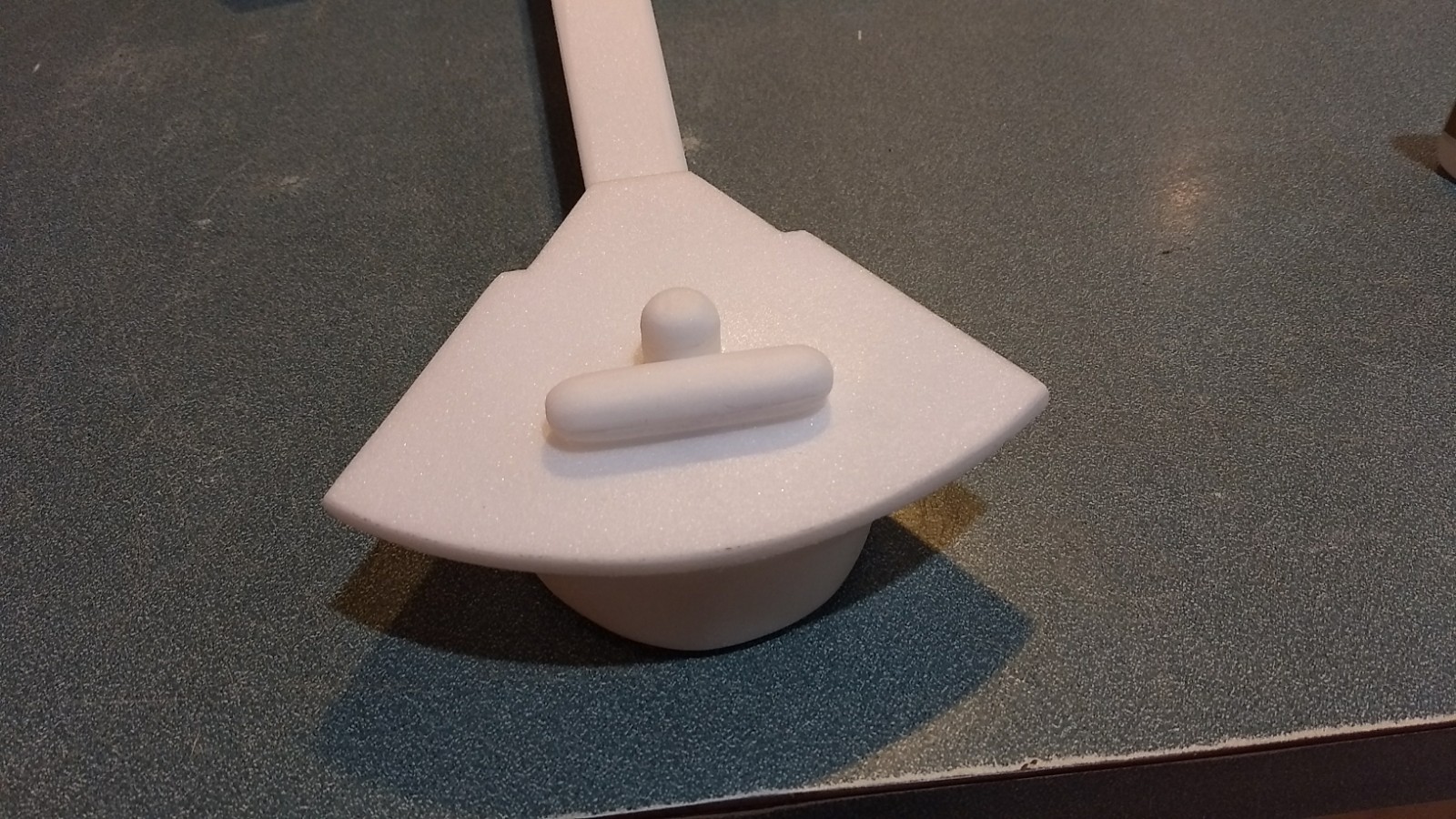
- Glue the bridge details to the top of the bridge. The major assembly is complete, you will do a pre-balance and then paint the model and do a final balance before flying. Paint adds about 1/2-3/4 ounce and the model can become tail heavy after painting.
- Insert your heaviest loaded rocket motor into the motor mount
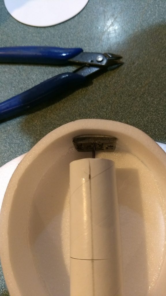
- Support the model at the balance point indicated for boost. I use two pencils with the eraser pointed up and held in place with a small hand vice. Place the model rightside up on the pencil erasers on the balance point indicated above. Use pieces of the included lead weight as far forward into the tip of the nose to balance it, as needed. Glue the lead weight in place so it does not shift during flight. Tape the plastic bottom plate in place when you balance so that it is included in the balancing. The model should balance slightly nose down. When done you can temporarily use masking tape on the inside of the plastic bottom plate to hold it in place during painting. Do not glue it in place till you have re-checked balance after painting.
- I can only recommend testors/model master enamel spray at this time, others I’ve tried damage the foam surface. I recommend flat colors as they dry faster and the surface imperfections of foam aren’t as noticable.
- Remove the battery, mask over the velcro, receiver, battery wire plug, servos and rail buttons. I used flat black spray for the vertical stab to help hide it during flight. Use a large plastic garbage bag and cut a slot for the tail, enclose the model in the bag and just mask the small portion around the base of the vertical stab. Try not to get overspray on the rest of the model as it will require more gray to try to cover and get an even color. Spray the vertical stab. Once dry, remove the bag, then cover the vertical stab with plastic wrap, and a small amount of tape at the bottom.
- Then lightly spray the model, you want just enough to look gray without adding a lot of weight. I used Flat Dark Aircraft Gray #1226. Don’t paint too close to the model or you risk melting the foam. The foam sanded edges and surface have a texture, it will not be possible to get a smooth shiny paint job like on normal smooth surfaces but that’s totally fine. When removing the masking for the vertical stab, If any paint pulls up just touch up with a small brush.
- You can use a black fine line sharpie to add panel lines or details if desired.
- Apply the markings to the model, the two silver markings go on the angle plates and the logo goes on the left wing. Once applied use a hair dryer on hot to lightly soften the markings and then rub them down with your finger to help them set down fully into the wing/paint.
- Re-attach your battery and loaded motor.
- Support the model at the balance point indicated for boost. Re-balance the model and add nose weight if needed. Glue the lead weight in place so it does not shift during flight. Do not try to fly the model too nose or tail heavy. Remember, a nose heavy model flies poorly, a tail heavy model flies once. Once balanced glue the styrene sheet in place. If you find the model twitchy on boost you can add more nose weight, simply pop the styrene sheet loose at the front and add weight and re-glue if needed. Alternately you can tack glue the plate in place, and glue permanently after test flights to be sure it flies the way you want.
Flying: Be ready on the first few flights to keep the model straight till you have the trims set perfectly for boost and glide. Try to do initial flights in dead calm conditions as I’ve found that this model will tend to pitch toward top of the model once off the rail if flying into a wind, it’s because the model is slightly tail heavy on initial boost. You need to be ready to react quickly to keep it boosting straight up or slightly away from you. Once you get it pointed in the right direction it normally doesn’t need much steering, on pitch, just adjust as needed to keep your boost angle. Keep the wings level. Count to 7 and start to push the model over level as the motor burns out and it slows down. Then click in the up trim. Once in a glide, if the model porpoises you have too much up trim for glide. It should have a gentle slow glide. The model doesn’t need a lot of control input to go left and right, avoid drastic bank angles which cause you to lose altitude. Gently fly around, and set up for landing when about 100′ high. The model will rock the wings if you start to get too slow, if this happens push forward on the stick slightly. The decent rate is very predictable, note the angle it is coming down at and head into the wing, keep the model level as it decents and gently flare just before touchdown. Try not to flare early and stall the model.
-
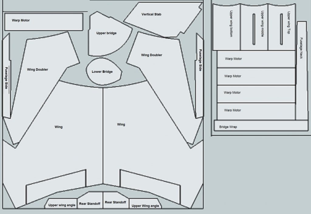
- Parts Identification
-

- Parts layed out
-

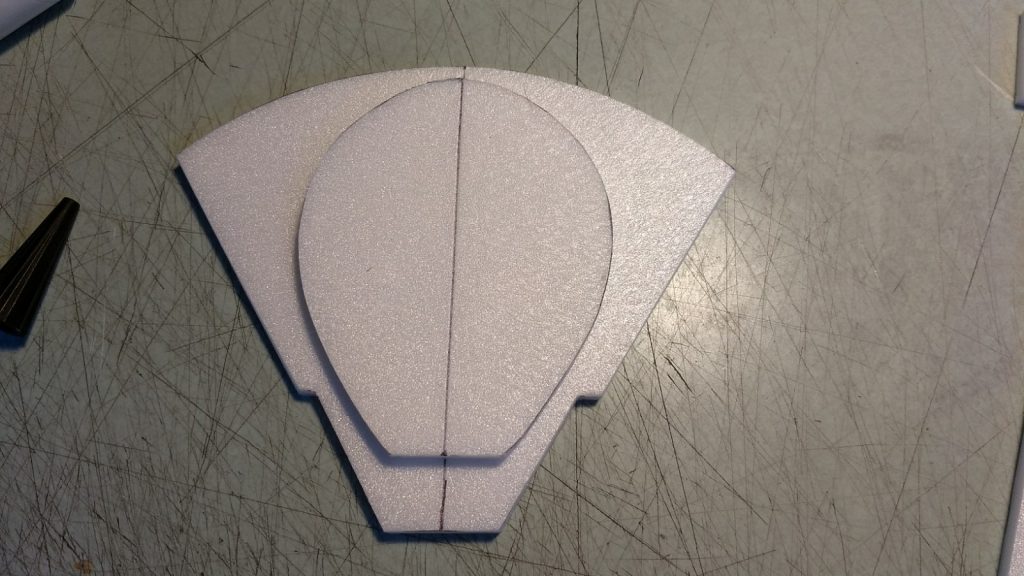
- Bridge details glued together
-

- Bridge details sanded to shape
-
- Glue the 2 oval bridge details together and the three circle bridge details together.

-
- Upper wing section laminated

-
- Stack and glue the three vertical stab mounting plates together using 3m-77 spray, then cut a bevel into the front edge.
-
- Front angle cut and sanded
-
- 45 degree angles sanded on each side

-
- Cut a slot for the vertical stab, then glue in place using 5 minute clear epoxy.

-

- Angled plates glued to the fin mount assembly
-

- Checking that angled plates don’t interfere with the elevons.
-
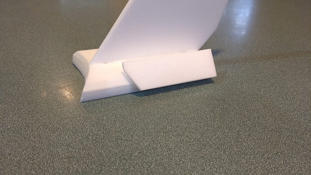
- Fin assembly complete

-
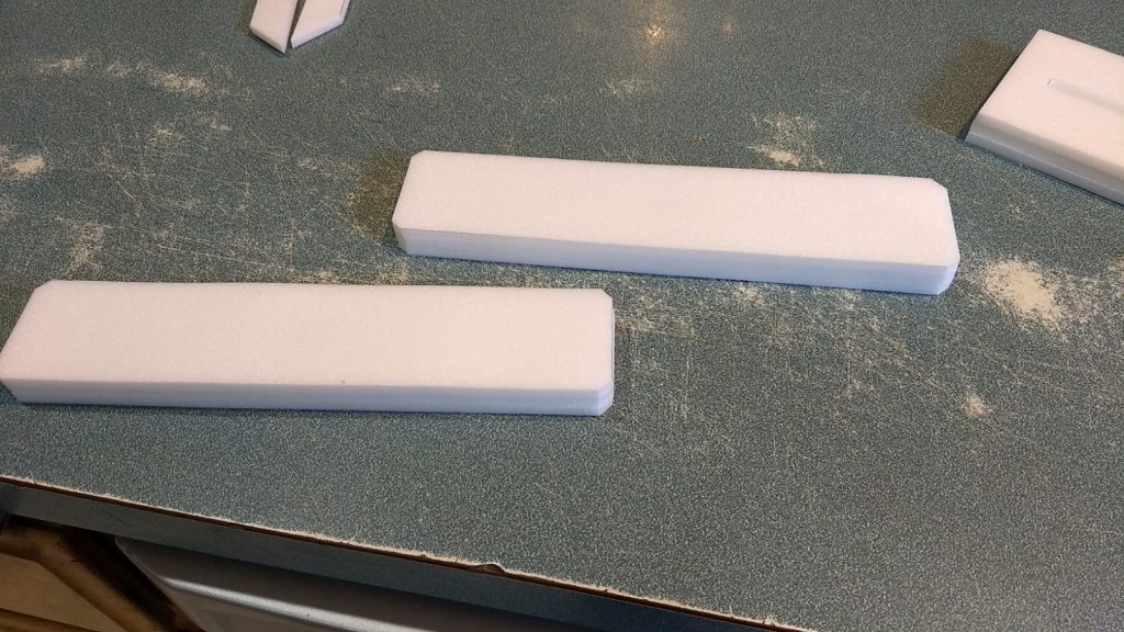
- Warp pods laminated
-

- Marking warp pods for sanding
-
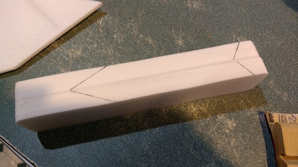
- Left and right warp pods marked for mounting location so those areas can be left un-rounded.

-
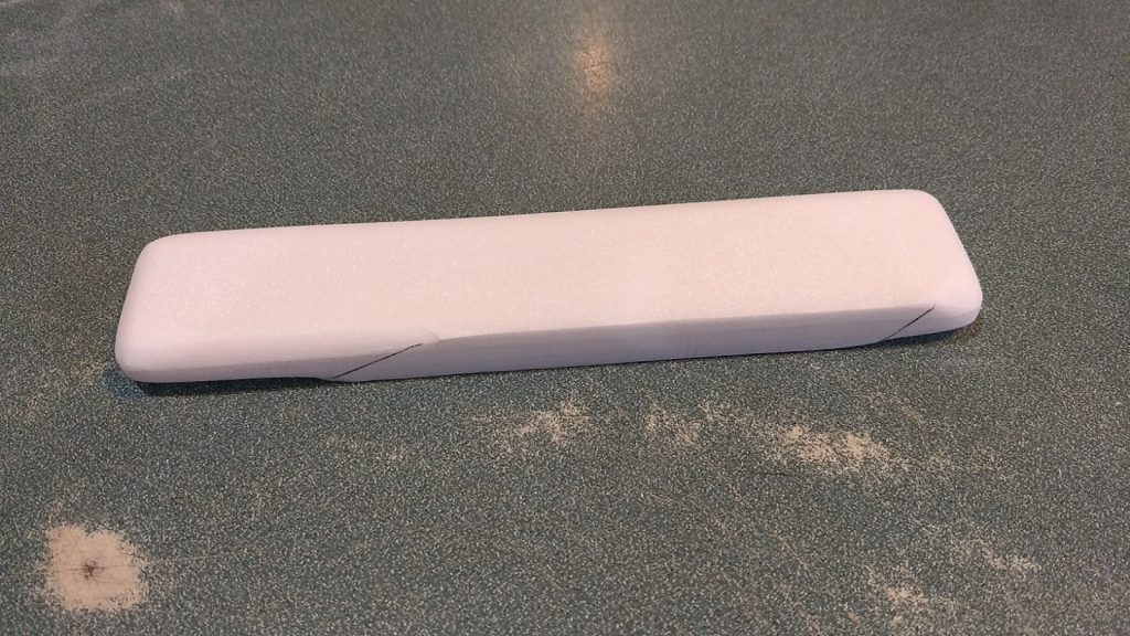
- Sand all areas round on warp pods except marked mounting areas.

-
- Draw a center line on the bottom of the bridge top plate and inner plate

-
- Draw a center line on the inner bridge piece, glue the inner bridge onto the bridge top leaving a 1/4″ gap at the front of the bridge.
-

- Mark the center of the bridge wrap then wrap and glue the bridge wrap against the inner and top bridge pieces using the center line aligned with the lower bridge center line
-
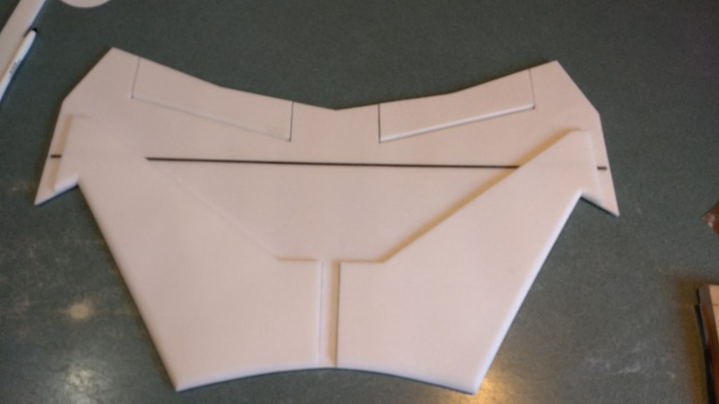
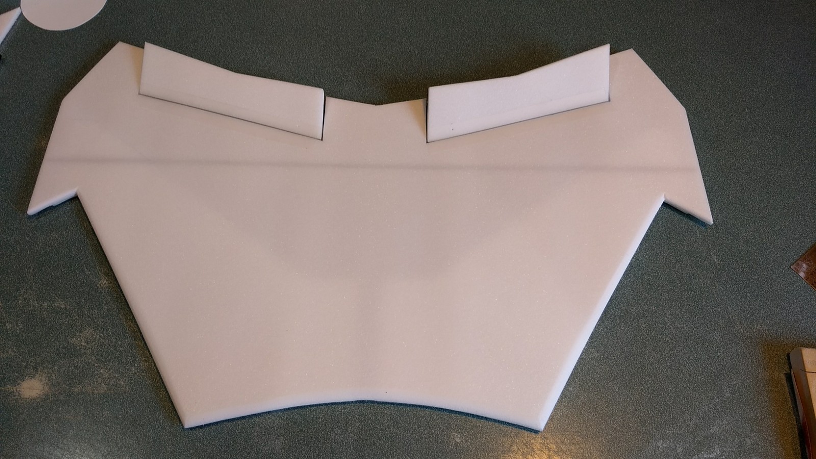
- Unfold the wing and glue it together along the taped joint.

-

- Glue in the spars(only one shown) and tape over them with the blenderm tape.
-
- Using the pre-marked lines, mask off the area on the bottom of the wing for the doublers and spray with 3m-77 spray adhesive, also spray the sides marked “glue” on each doubler.
-
- Carefully place the wing doublers onto the bottom of the wing, the leading edges should be aligned, there should be approx a 3/4″ gap between them in the center for the body tube.

-

- Sand the leading and trailing edges round at this time if you wish. Do not sand the wingtips yet, that will be done after you install the motor pods.
-
- Glue neck to wing, using straight edge for alignment. It helps to draw a line down the middle of the neck and wing. Sand the rear of the neck at an angle to match the rounded leading edge of the wing to make a nice flush joint.
-

- Fuselage side pieces glued against wing and body tube
-
- Rear center support plates glued just forward of the rear of the side fuse pieces

-
- View of rear support plates
-
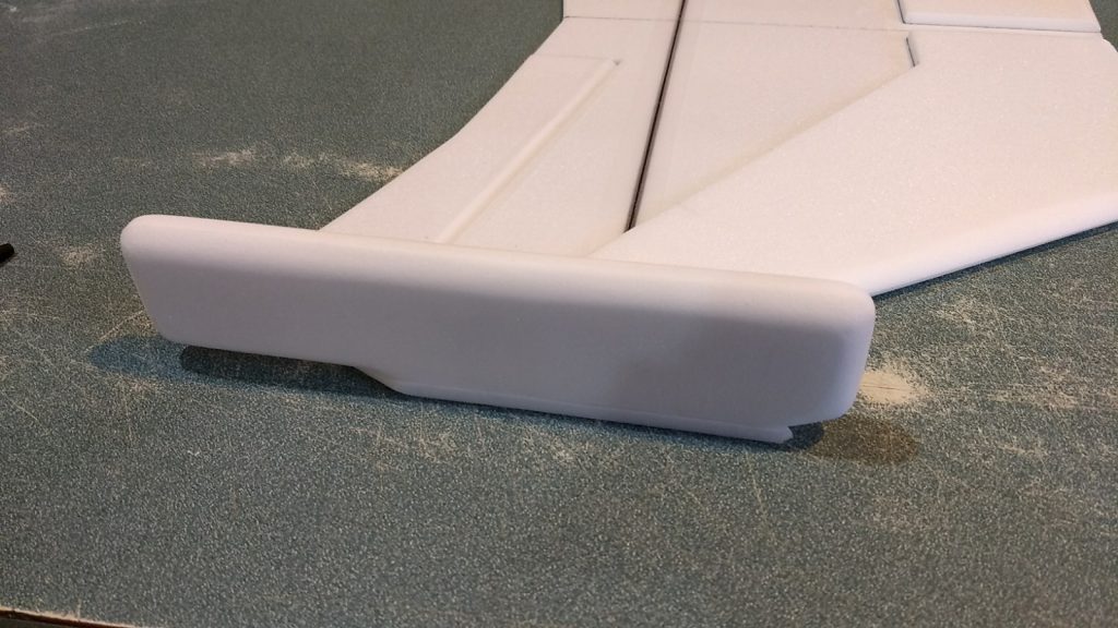
- Warp pod glued in place
-

- Top of wing sanded round into warp pod.
-

- Pushrod and horn installed
-
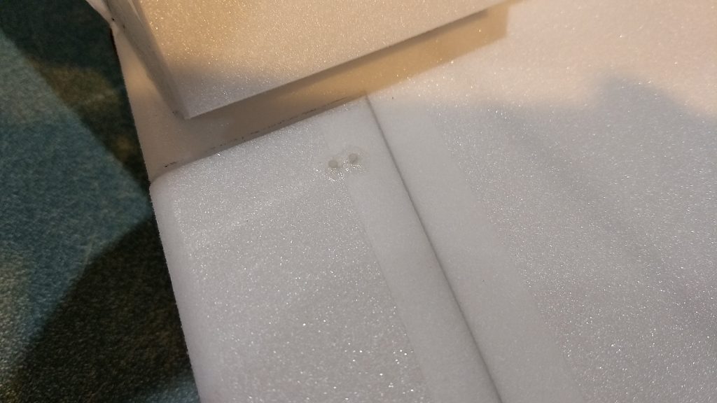
- CA+ on the top of the control horn prongs to lock them in place
-
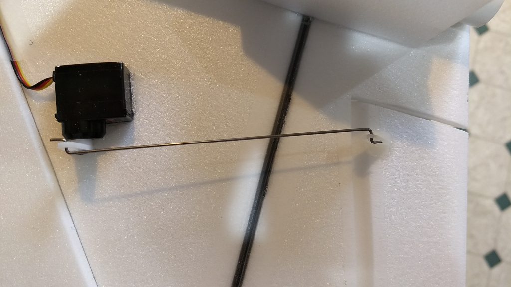
- Servo installed

-
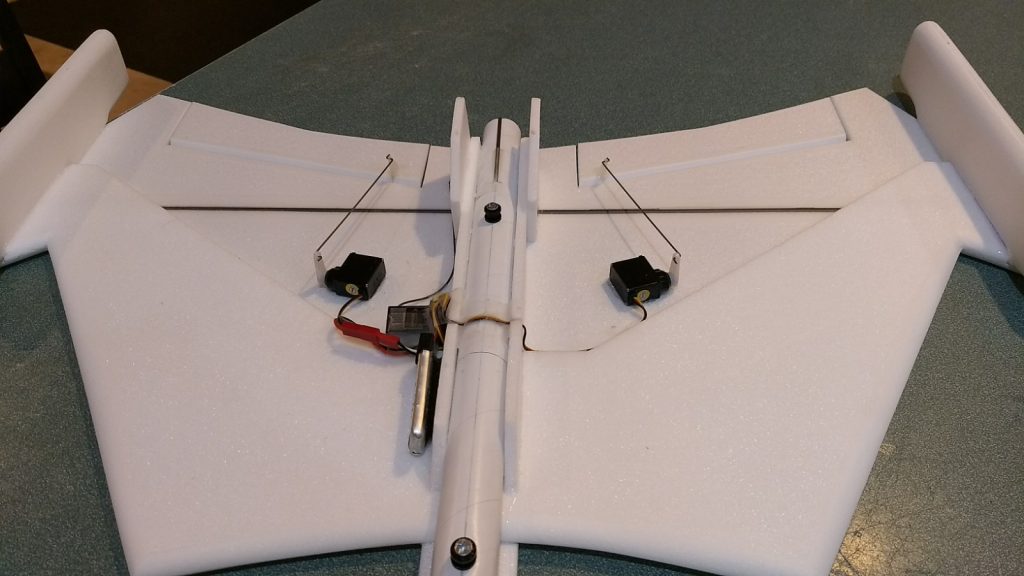
- Pushrods and Servos installed. Pushrods should be straight out from the hinge line, and will be at an angle with respect to the fuselage, this is ok.

-
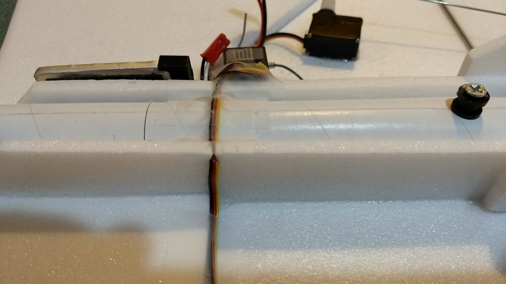
- Showing how servo wire is routed through foam and over body tube to other side for connection to recevier, wires are then taped down to prevent rail from dragging on them.

-

- Other side of fuse showing receiver and flight battery with wiring taped down
-
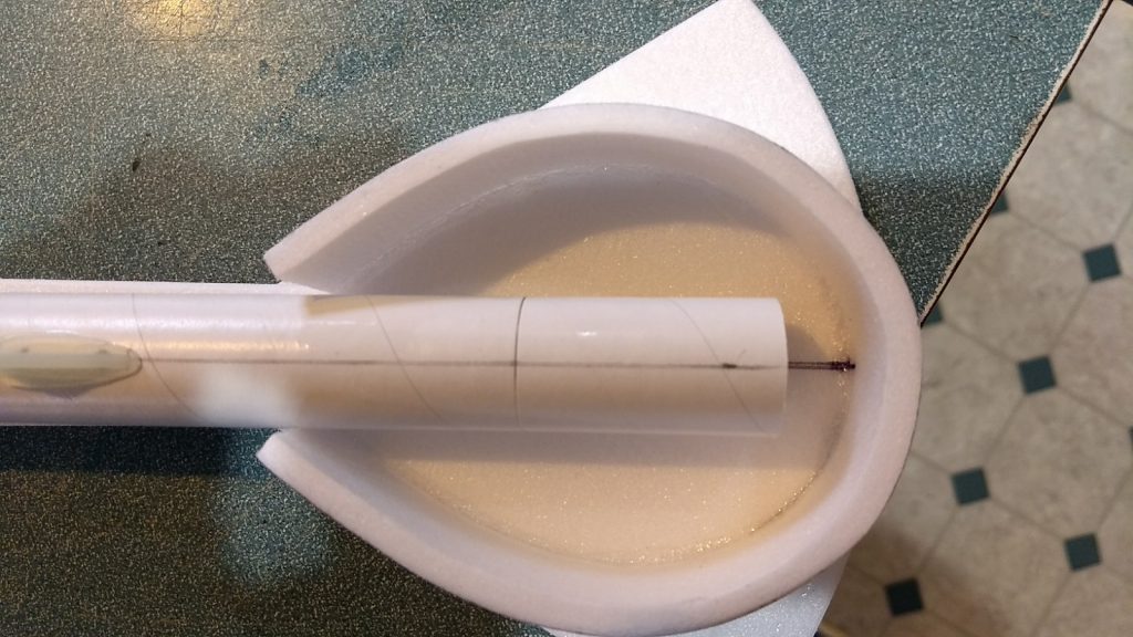
- Forward bridge glued in place. The Neck butts against the inner bridge piece and there will be a gap to the front to place the nose weight.
-

- Bridge detail glued in place.
-
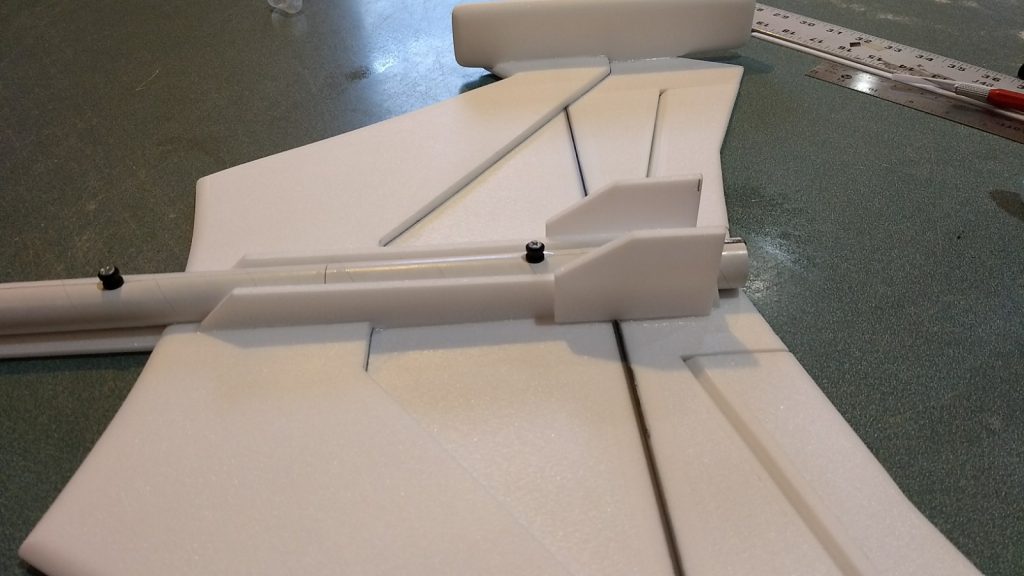
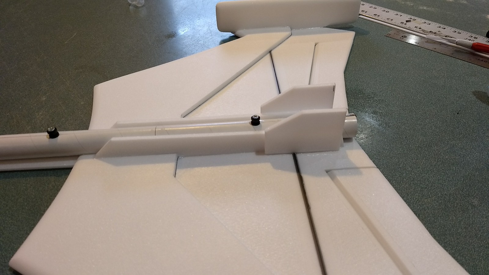
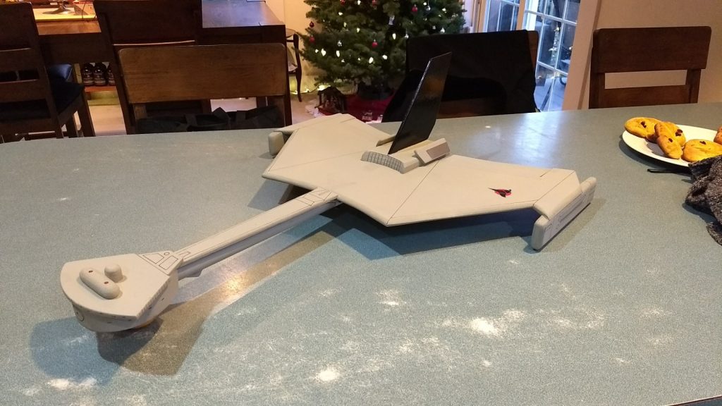
- Vertical stab/upper wing assembly glued in place

-
- Insert a loaded motor in the model and balance as per instructions. Add nose weight as needed in the front of the bridge. Tape the bottom styrene plate in place when balancing.

-
- Once model is complete and painted, balance with a loaded motor as per instructions. Once balance is achieved, glue the bottom bridge plate in place.

-

- Motor pod detail lines.
-
- Upper wing details

-
- Bridge details
-
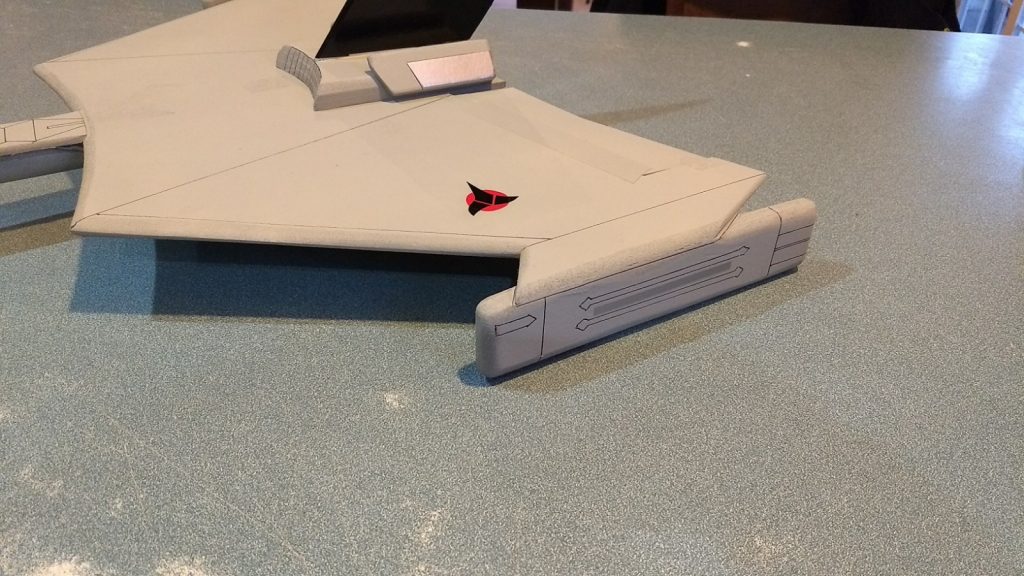
- Wing logo
-
- Slight downtrim for boost
-
- Slight up trim for glide

-
- Full up elevator throw

-
- Full Aileron throw

-
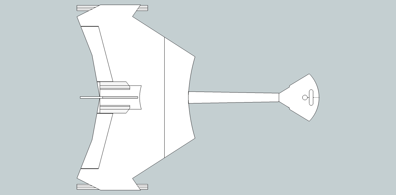
- Assembly upper bridge view

-
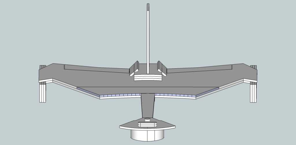
- Assembly Front view
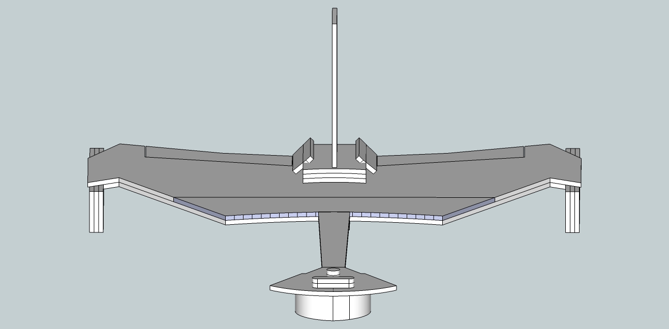
-
- Assembly Bottom view
-
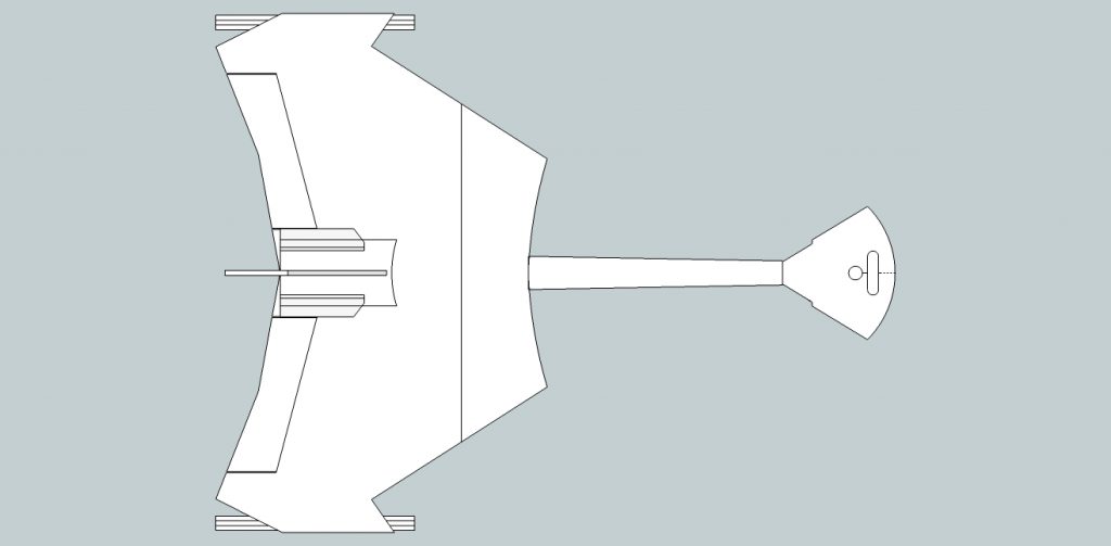
- Assembly top view
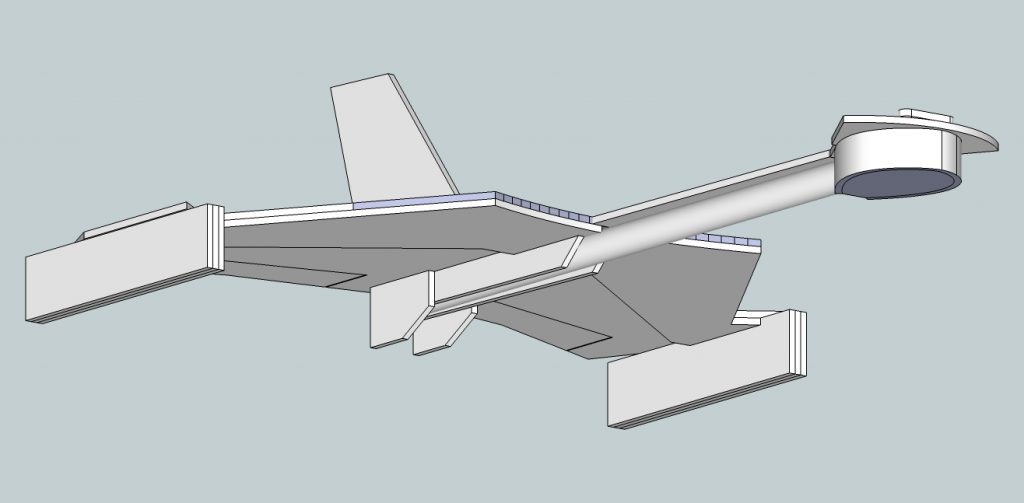
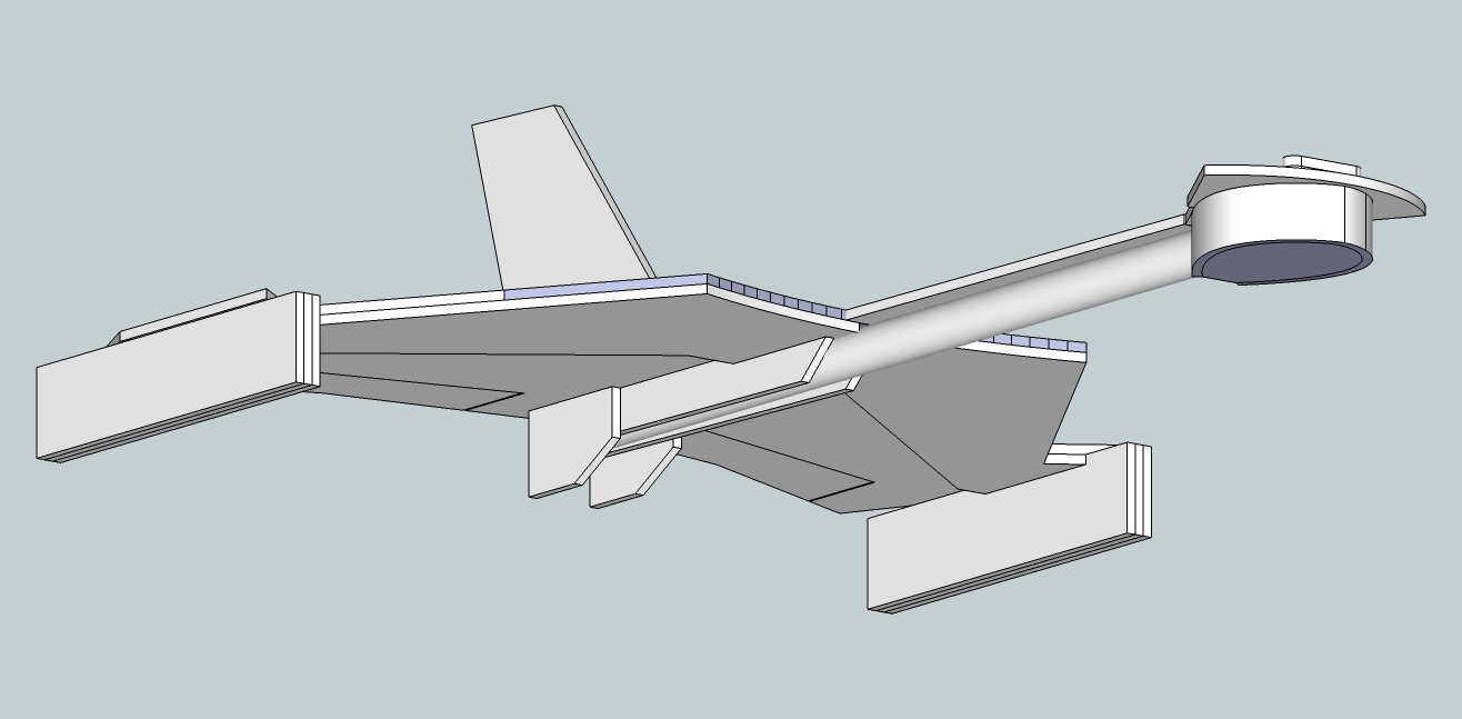
-
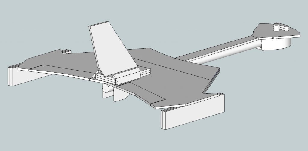
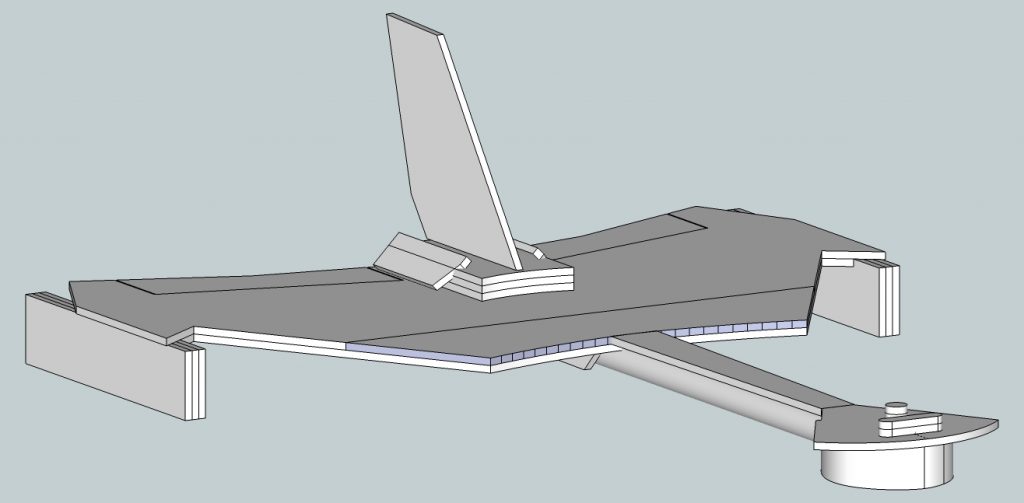
- Assembly side view

-

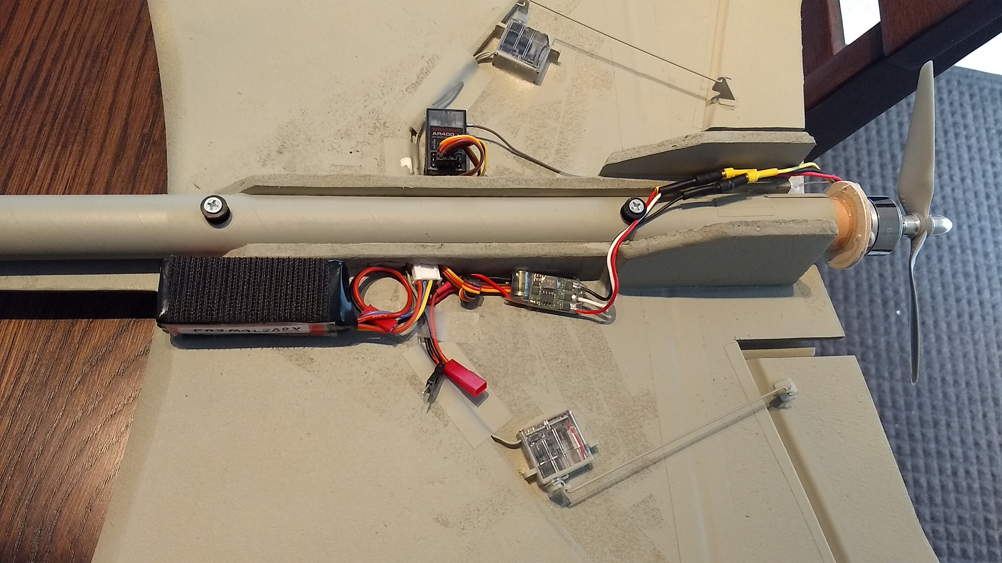
- Electronics placement for Pusher motor, receiver on left side, battery, esc on right. Extra plug show is for the LED in the nose that can plug into the battery balance plug if desired.
Additional notes if you are planning on flying this with an electric motor:
Recommended components:
Grayson Hobbies Microjet V-3 motor weighs around 34 grams. You can get it with an ESC for around $22 but the esc is heavy.
apc 6×4 electric prop
1/4″ by 1/16″ diameter wood screws(need 4) for mounting motor to ply mounting plate
Venom 3S 800mah lipo battery with jst connector (eflite makes one too, you want it to not be heavier than 2.3-2.4 ounces and have a 25c or better rating.
Ply plate and adapter tube to fit into motor tube to mount electric motor.
When setting up for pusher propellor, you will need to add the extra velcro for the battery and esc, and then balance with the electric motor and battery in place, typically that requires some additional nose weight that you will not need for rocket flight, so you may want to just velcro the weight to the front of the model so you can remove it for rocket flight. Remember the pusher CG is further forward than the rocket CG.