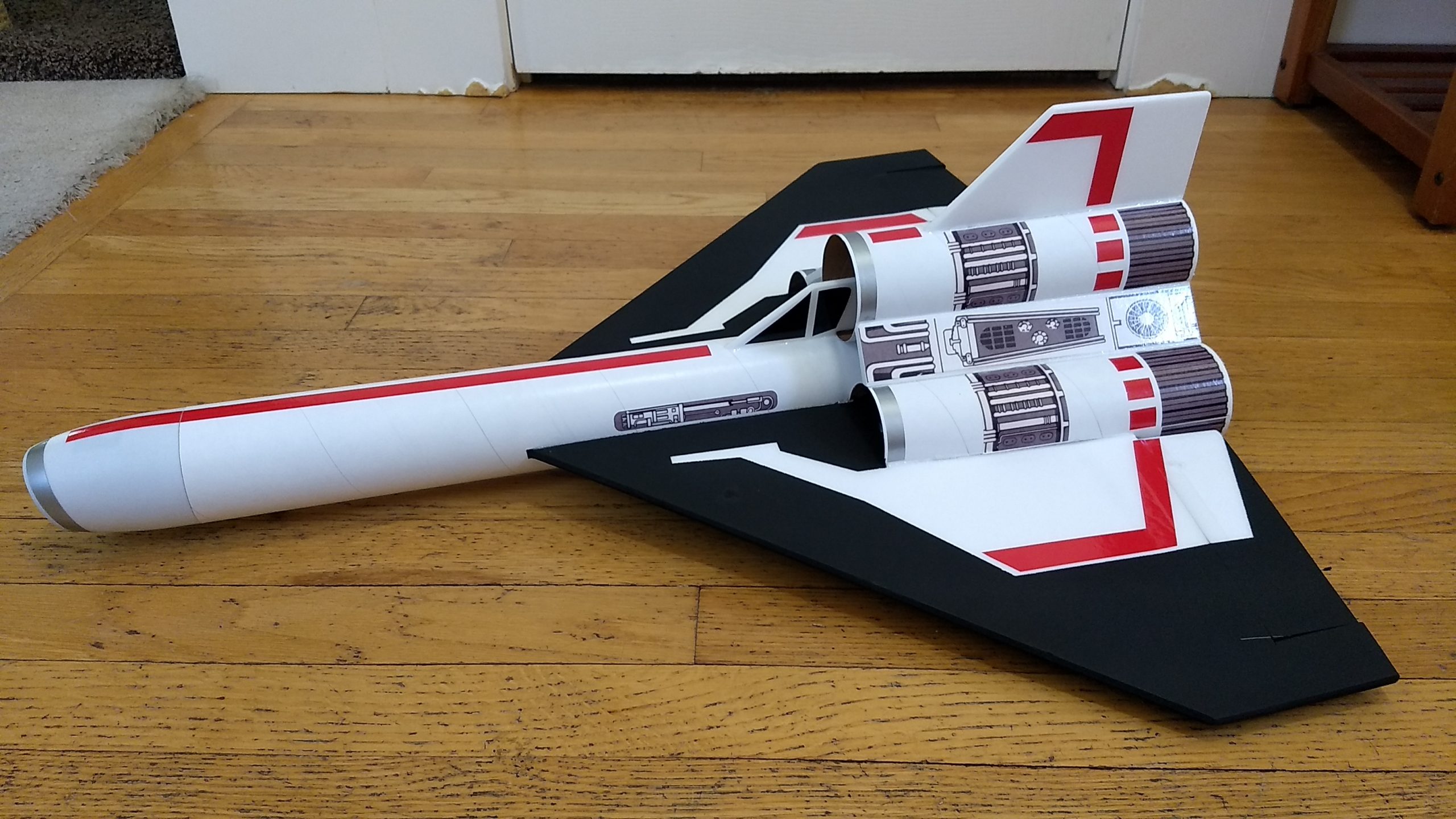
The Colonial Viper RC rocket glider kit is based on the classic Battlestar Galactica fighter. The model features pre-cut nose cone, pre-fit wing spar, elevons are pre-hinged, rail button holes are pre-cut. 6mm depron foam surfaces keep weight light, body tubes are pre-slotted for the wing and tail surfaces. The wings are oversized for glide performance and you simply mask and paint the oversized wing portion flat black using the template provided. Wingspan 23″, length 27″, weight ready to fly 12 oz.
Printed Viny Click here for Vinyl Decals for this kit
CG ready to boost at 10.25″ forward of the rear end of the main body tube.
Unpacking your kit:
The kits are packed to protect them in shipping, but the contents are fragile so unpack carefully. Carefully cut the tape holding the tubes in the box, then unwrap/lightly cut the plastic wrap to free the tubes, the spar may be packed in the tubes and the baggie with the little parts and nose cone will be in the tubes as well. Carefully cut the tape holding the cardboard wing protector in the box and carefully remove it, don’t pull hard or bend it. Then carefully cut the tape holding the cardboard top piece to the bottom. There may be some sticky tape holding the cardboard to the bottom cardboard piece, carefully peel it being sure not to bend anything. Once the top cardboard is free you can see the foam wing/tail parts, there are little fragile pieces in here, so unwrap carefully. It may be best to use an exacto to lightly cut the plastic wrap and carefully remove it without cutting into the foam. Make sure everything is free before you remove the pieces to avoid breaking anything. Kits contain one or two scrap pieces for repairs if you damage anything in construction or flight, just cut and patch in a spare piece of the foam if needed using foam safe CA+.
Welcome to the world of rocket boosted radio control gliders. This is not a model for a novice RC pilot, but anyone who is comfortable with RC flying of a medium speed model should be fine. Read through the instructions, look at the photos and be sure you understand the step before committing to cutting or glue.
Identify all pieces, the kit should contain:
1 wing taped together
1 wing spar
1 blenderm tape
1 Nose Cone
1 vertical stabilizer
2 wide foam strips for upper nacelle fillers
2 narrow foam strips for lower nacelle fillers
2 control horns/Pushrods
1 long body tube
2 side nacelle tubes slotted all the way to the front
1 upper nacelle tube slotted for the vertical stab only.
Motor mount
4 13/16″ x 2.5″ wide strips to center the motor tube
Velcro(for battery and rx/bec attachment)
2 Rail buttons with t nuts/screws
1 canopy foam piece
Spare foam
Lead weight
Notes before starting:
Foam safe CA+(Bob smith super gold + is good) is the only glue recommended for construction. You will also need foam safe accellerator to set the glue.
I beveled the edges of the wing leading and trailing edges, vertical stab leading edge, and the leading edge of the cockpit with a straight edge and exacto knife. Just a small 1/16 to 3/32″ bevel on both sides looks good and is easier and less messy than sanding. Do any shaping before assembly.
Assembly:
- Press the front of the nose cone into a piece of the spare foam to make an indent of the nose shape. Cut this out with a knife and press it into the nose cone from the inside. Glue in place to block off the open cone, I inset mine about 1/8″ and then painted it flat black.
- Apply CA+ to the taped wing joint, and set it on a flat place. Once cured, glue in the wing spar then tape over the spar and center joint.
- Test fit then glue the wing into the body tube slot with the wing centered.
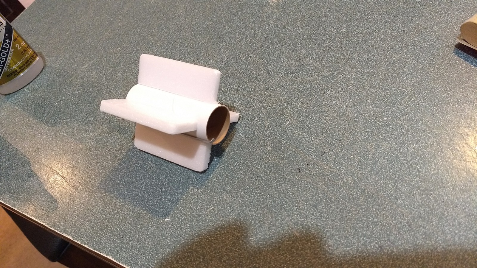
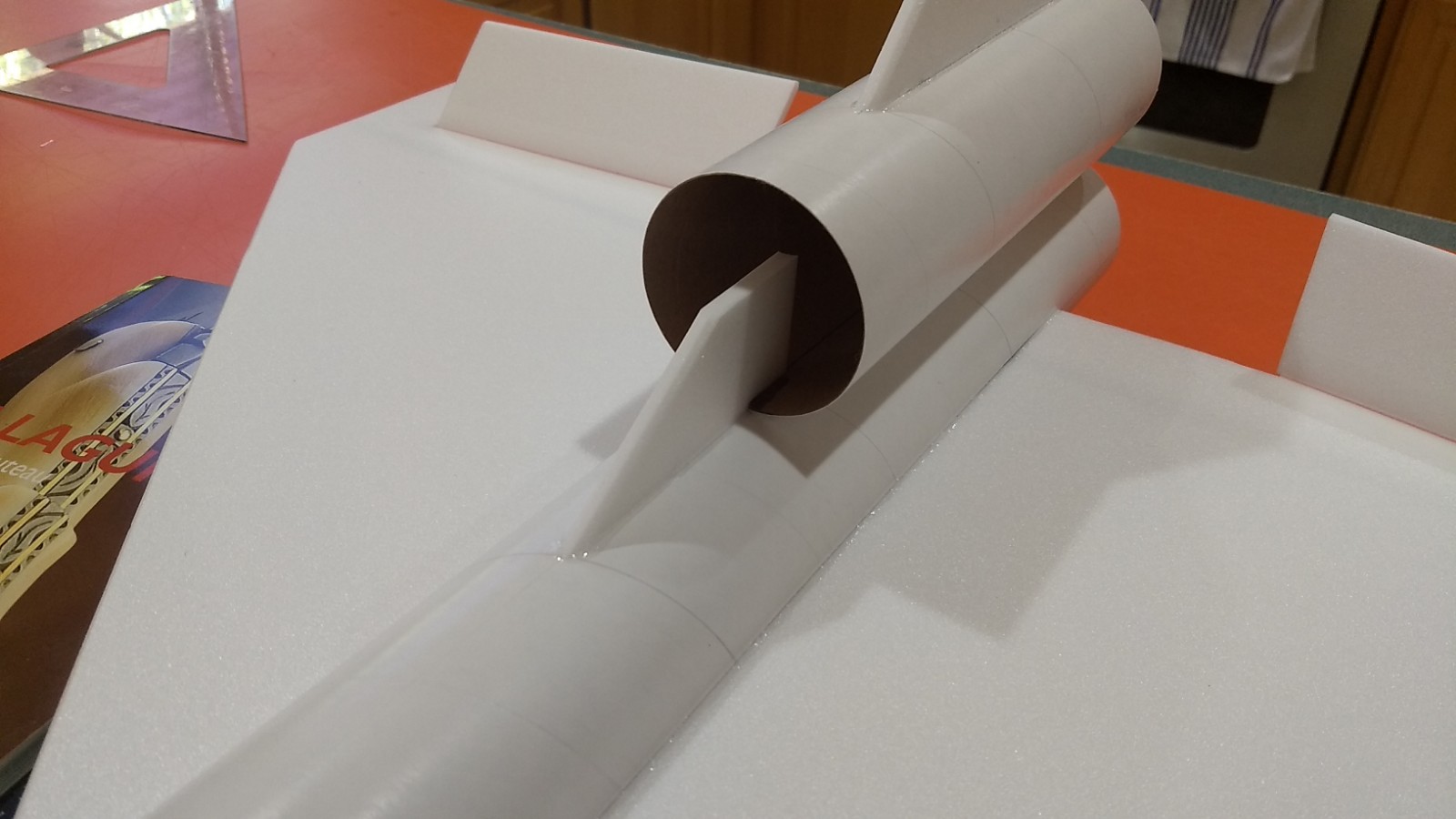
- Glue the vertical fin into place in the one nacelle with a single slot, note the tube has a line inside at the bottom to make sure you keep it vertical when you glue. Set the model upright with the wingtips raised equal amounts and then glue the thruster tube and fin to the body tube keeping the rear of the tube even with the rear of the body tube. Make sure the vertical fin is straight up and down using a triangle or something similar.
- Glue the cockpit piece in place inset into the top nacelle about 3/4″.
- Glue four 2.5″ long foam strips on the motor tube using foam safe CA+. These tabs help center the motor tube in the body tube. If the lines aren’t perfectly aligned use your eye to make them evenly spaced.
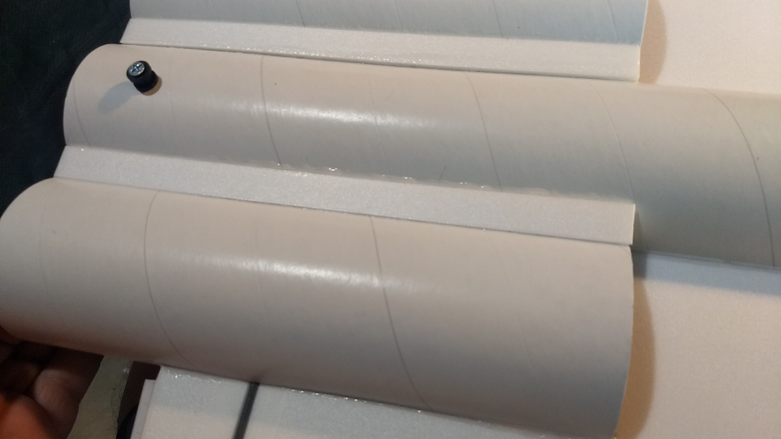
- Install the front and rear rail buttons in the pre-made holes in the body tube at this time.
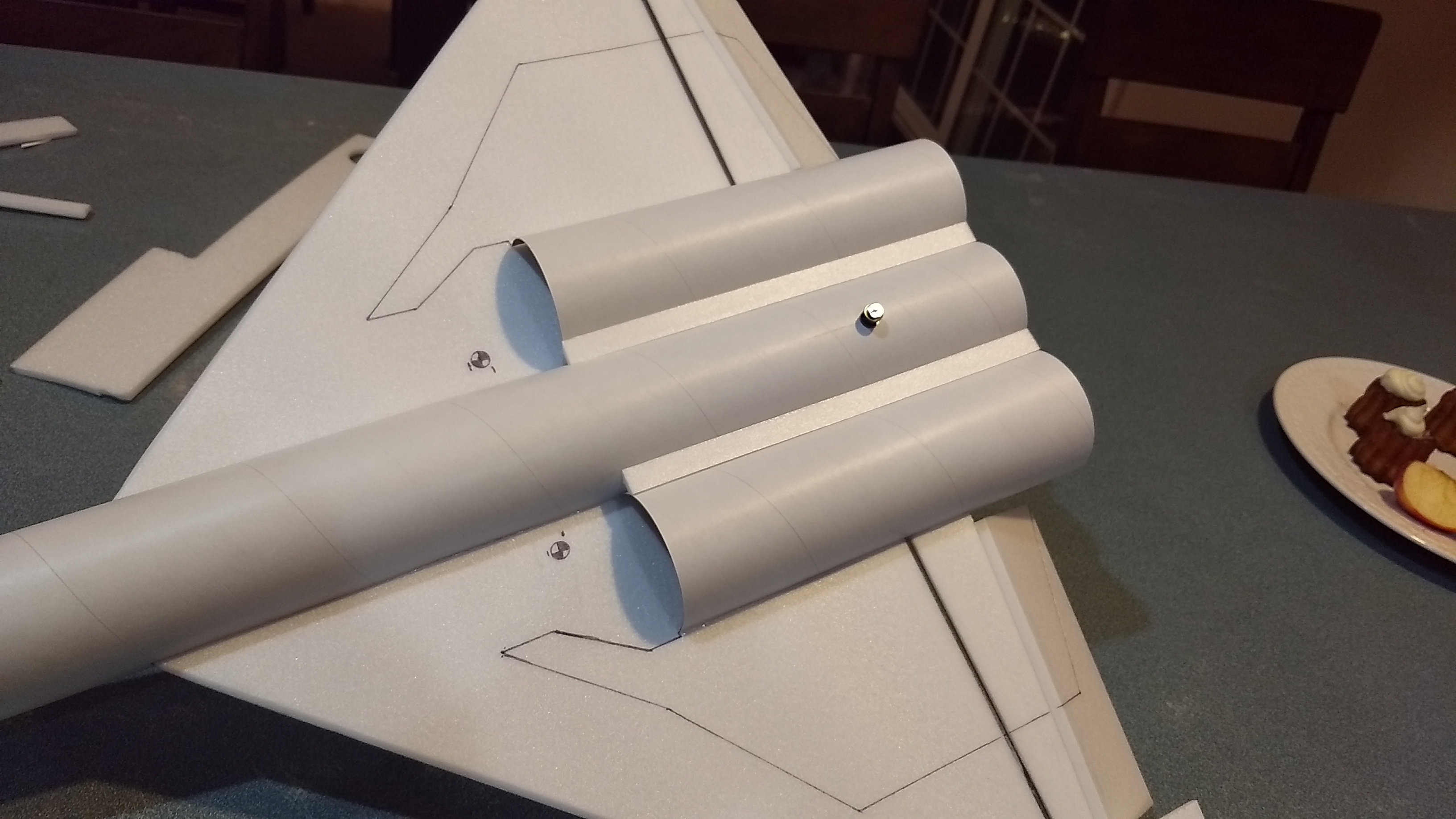
- Test fit the motor mount into the body tube Make sure it fits, or sand the foam tabs lightly. Glue the motor tube in place, it will inset into the wing cutout slightly and be flush or slightly recessed into the body tube. **Note, you will need to rotate it so that the tabs clear the rear rail button! Put a fillet on each side of the motor mount tabs and fuselage.
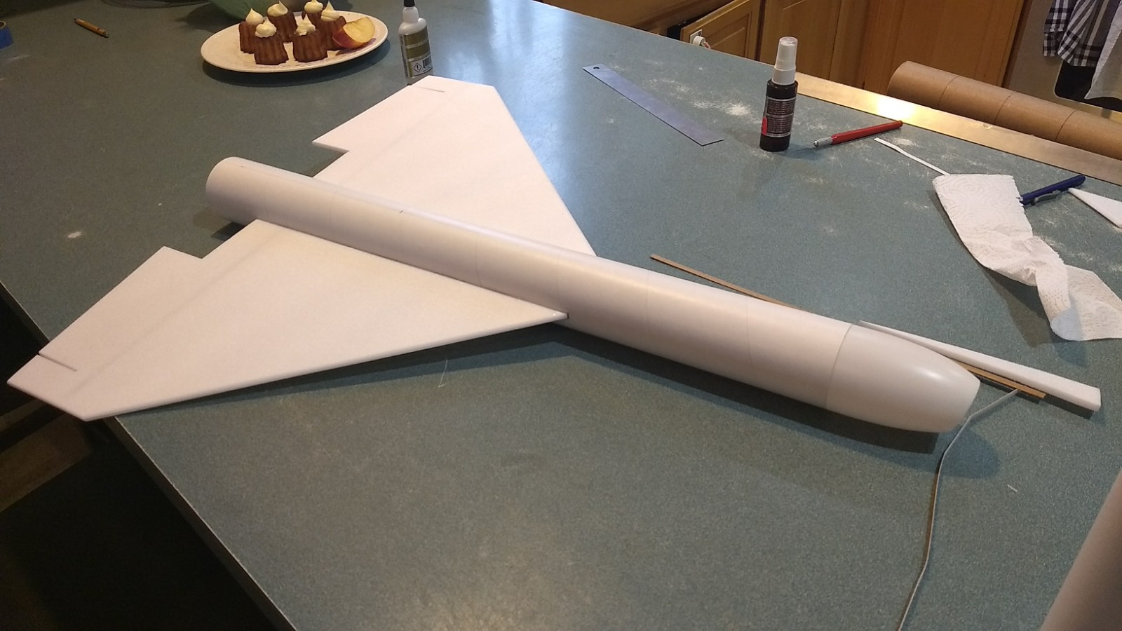
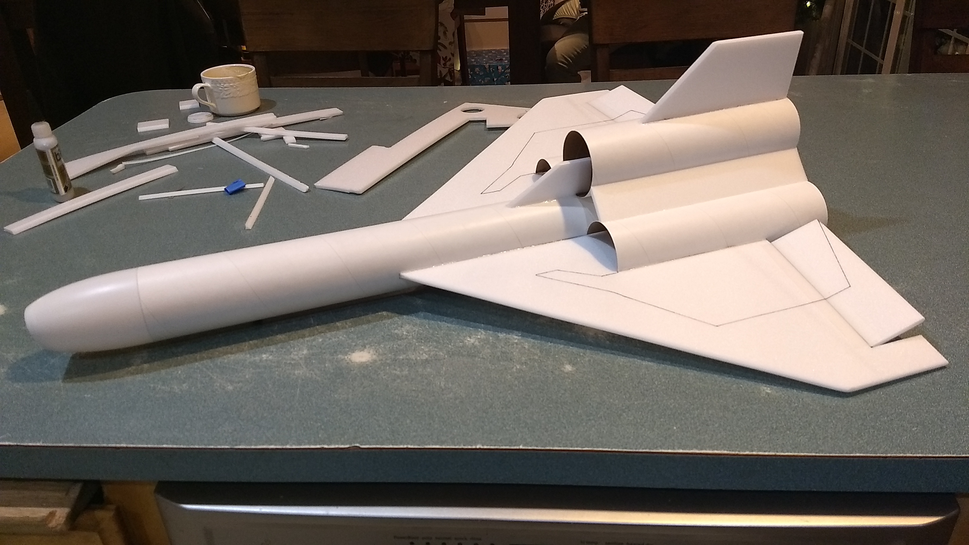
- Test fit the side nacelles onto the wing. Make sure the nacelles are butted against the main body tube as close as possible. Glue in place.
- Test fit and install the filler plates between the nacelles. The wider ones go on the top and the narrow ones on the bottom. The edges are cut an an angle to help them make better contact with the tubes.
- Painting: I can only recommend testors/model master enamel flat black spray, others I’ve tried damage the foam surface. Use the Dowloadable template HERE: to mark and mask off the wing area that is supposed to remain white and mask rest of model as well, then spray light coats. Make sure not to hold the paint too close to the model. It’s easier to paint and mask before radio/servo/control rod installation!
- If you chose to get the stickershock decals follow these steps:
- Use the pictures as a guide for installing the decals. The decals for the motor nacelles are slightly oversize to allow for the placement of your filler plates and require trimming before installing. The short corrugated looking wraps go on the rear of the nacelle, the short wraps with piping go a little forward of center of the nacelle. The longer corrugated piping wraps go on the bottom of the nacelles.
- Apply the filler plate decal, it will need to be trimmed at the rear about 1/4″ to fit.
- Apply the vertical stab and wing pre-cut red stripes
- Apply the long gun detail marking as shown just above the wing.
- Apply the cockpit markings to the left and right cockpit.
- Apply the nacelle corrugated and piping wraps to the bottom of the nacelle tubes.
- Use one of the long red strips for the top of the body tube just ahead of the cockpit to near the end of the nose.
- From the remaining long red stripe cut a 1.25″ long piece to go just ahead of the vertical stab on the nacelle front.
- From the remaining long red stripe, cut (12) 5/8″ long pieces to go just ahead of the upper nacelle corrugated wraps. They should line up with the red vertical stab and wing and be evenly spaced as shown in the pictures.
- The two gray strips are used for the tip of the nose cone and the nacelle intakes on each side.
- After application of the markings use a hair dryer on hot to warm the markings and them push them down into the foam surface with your finger. They will really conform and stick down well.
- Apply CA+ to one of the control horns and press it in place on the BOTTOM of the control surface in the pre-made holes. Note The control horn holes face forward and the pushrod should be closest to center of the wing. Repeat for the other side. Apply a fillet around the control horn on the the prongs on the top of the wing to lock them in place. This completes the airframe assembly, next is radio installation.
- Your radio needs to be configured for Delta mixing, this means that the servo arms will move the same direction during elevator stick movement and opposite for aileron stick movement. Connect your servos to the receiver one in the aileron connection and one on the elevator connection and apply power. Use a servo arm at least 9/16” long and with holes small enough that there won’t be slop with the pushrod wire when installed. I use the hole furthest out on the servo arm, to maximize movement. On some servos there are a long two-ended servo arm, you can trim off one end and use that arm to get sufficient length. Zero out any trim settings on the transmitter.
- Flip the model upside down. Connect each servo to a pushrod. Each servo should be on the bottom of the wing, with the servo electrical wire pointing forward and the servo arm pointing toward the wing tip. Tape each servo in place so that the control surfaces are centered, the servo will be in the next to the nacelle for now. With the model right side up look at it from the rear. Moving the transmitter stick back(up elevator) should move both elevons up. Moving the transmitter stick to the right should move the right elevon up and the left elevon down. If you can’t get the servo reversing to give you the right polarity try swapping aileron/elevator inputs to the receiver or turning the servos over and swapping the servo arms to the other side of the output shaft. If that is correct, continue.
- Hold the servo next to the nacelle and mark with a pencil where the servo outline will be on the nacelle and carefully cut out the nacelle to make a pocket for the servo to sit in. Check the fit, make sure you can install the servo flush with the outboard side of the nacelle and that the control surface is level. Cut the servo pocket more if needed to fit properly.
- The servos may be attached to the model using double back servo mounting tape(not included) or by directly gluing the servo to the wing with foam safe CA+. Double back servo tape can loosen over time and with exposure to heat, I prefer to glue the servo in place. With the radio still on, put a moderate amount of glue on the servo, being careful not to get any near the output shaft, and set it in place on the wing in the pocket in the nacelle keeping the control surface centered. Do the same to the other side. Be careful not to get any glue near the output shaft of the servo.
- Attach a 12-16″ servo extension to each servo. You just need to have enough length to be able to route the wire into the body tube and out the front to attach it to the receiver.
- Make a 1/8″ wide by 1/2″ long slot in the main body tube on each side just ahead of the front of the nacelles for feeding the servo wire through into the body tube. Route servo wires through to the inside and toward the front on each side. Use the blenderm tape to tape the servo wires down to the wing.
- Re-Attach the servo wires to the receiver and make sure they are going the right direction.
- Make sure the control surfaces are centered, use trims if needed. Now measure the control surface movement. Full elevator movement should be 1/2-5/8″ in each direction, aileron movement should be 3/8-1/2″ in either direction.
- If you have a flap/elevator mix you can program up elevator trim for boost and glide and assign it to the flap switch. If you can’t set the up elevator trim to a switch on your radio you’ll have to manually put in boost and glide trim using the trim tabs which is hard to do while flying the model. My model needed a small amount of down trim, approx 1/8″ for vertical boost and the model needs approximately 1/4″ of up trim for glide.
- Use the included Velcro to attach the receiver and battery inside the nose cone, I put the battery at the bottom of the cone and the reciever at the top.
- Re-install the receiver and battery
- Insert your heaviest loaded rocket motor into the motor mount
- Support the model upside down at the balance point indicated for boost. Glue the necessary amount of the included lead weight in the nose to balance it slightly nose down. Do not try to fly the model too nose or tail heavy. Remember, a nose heavy model flies poorly, a tail heavy model flies once
Flying: See the General Instruction link at the top for flying instructions. Be ready on the first few flights to keep the model straight till you have the trims set perfectly for boost and glide.
-
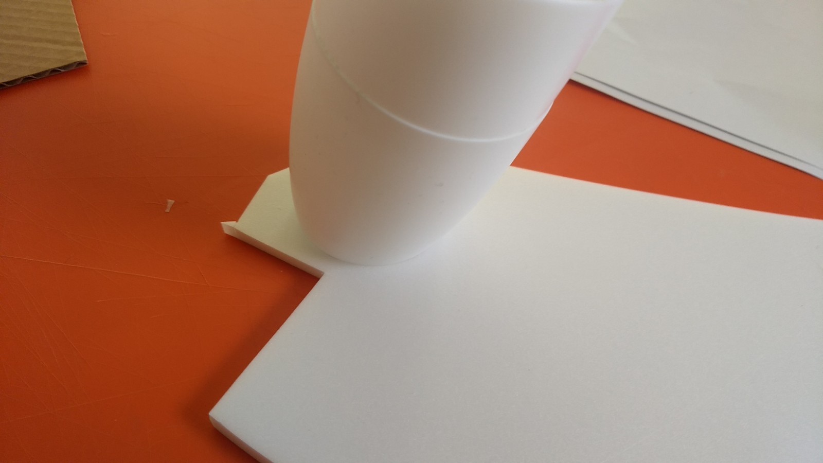
- Press the nose cone into a piece of spare foam included.
-
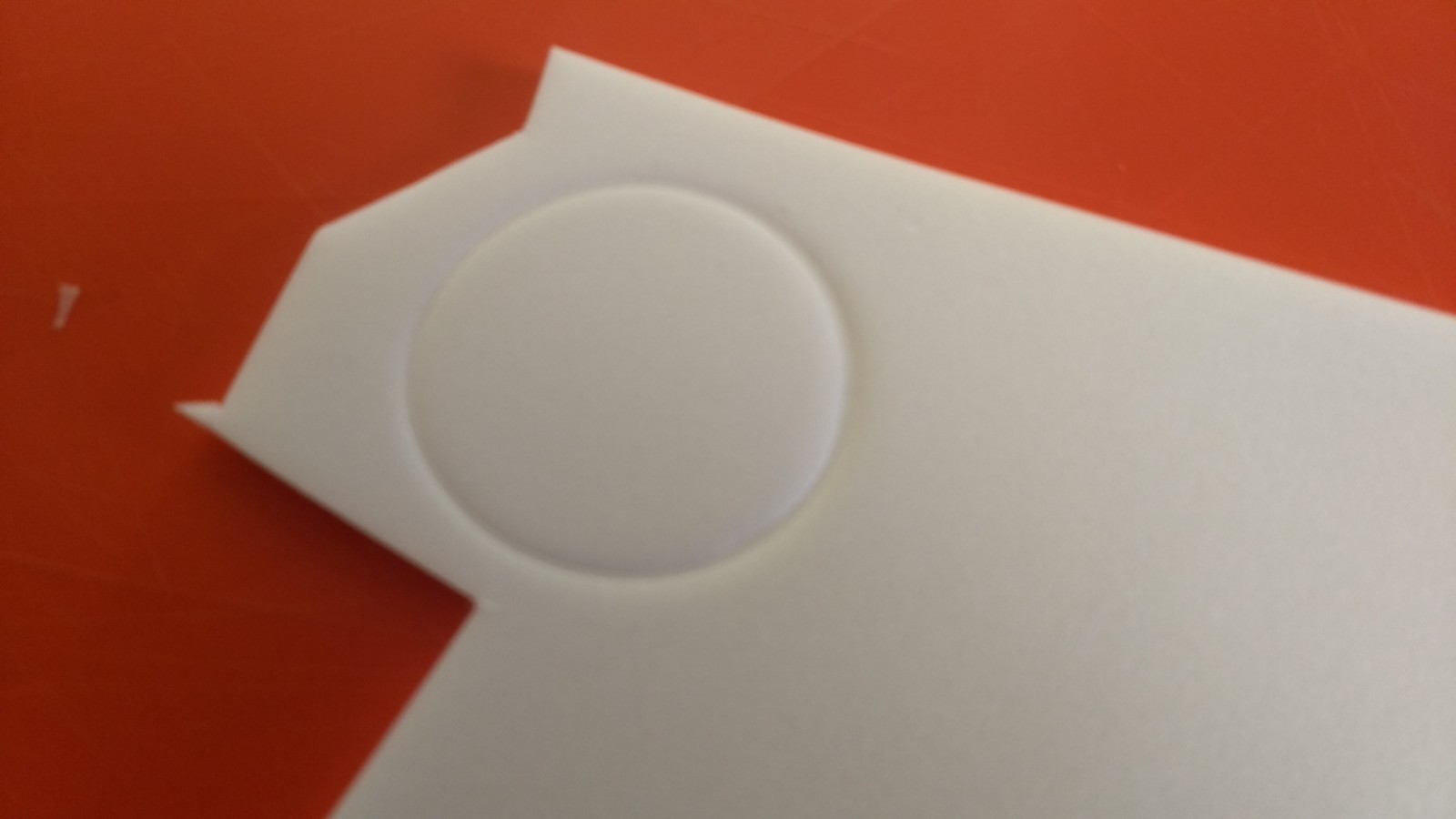
- Cut out the nose filler
-
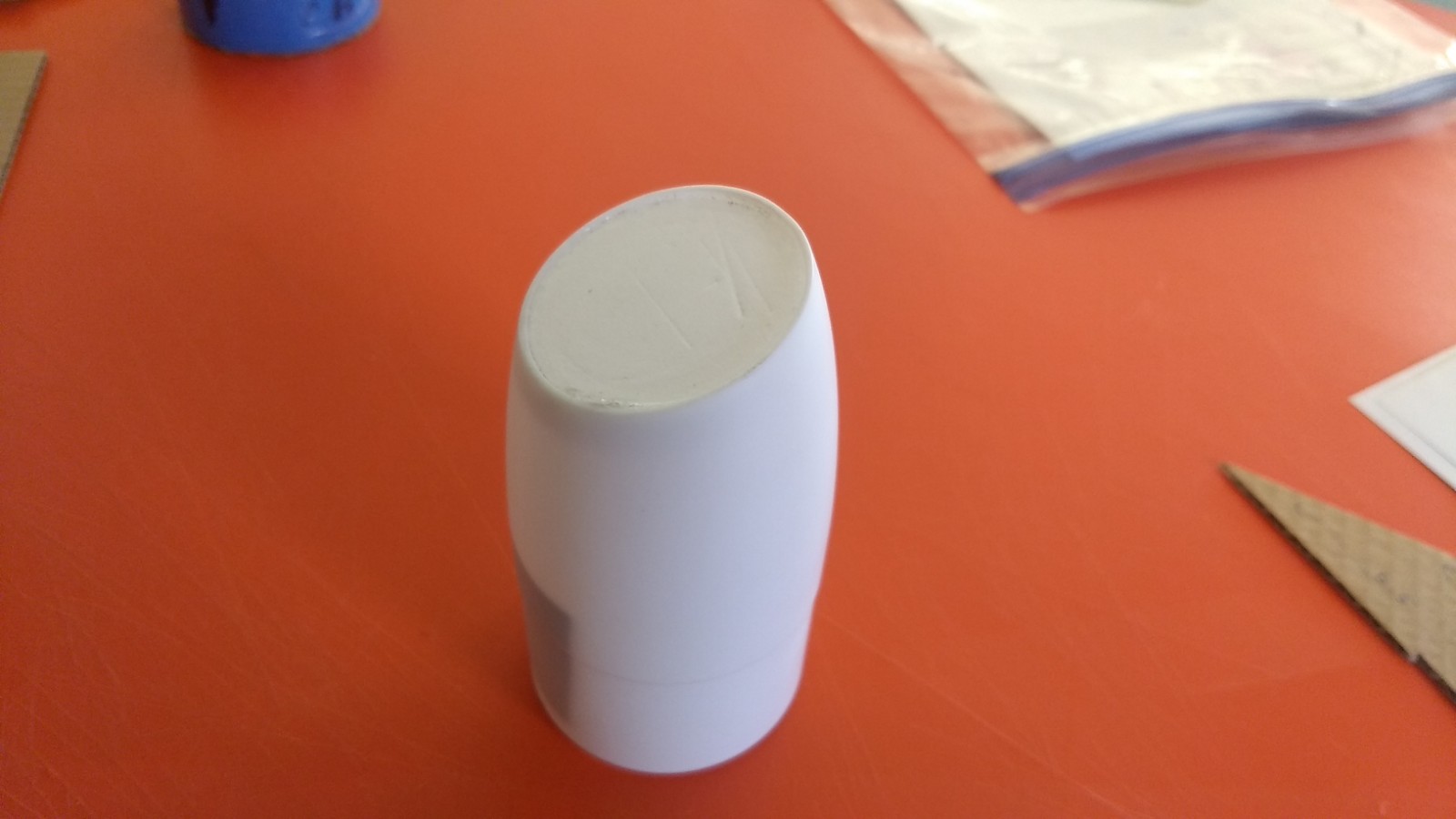
- Glue the nose filler into the nose cone from the inside, it will be recessed slightly.
-
- motor mount.
-
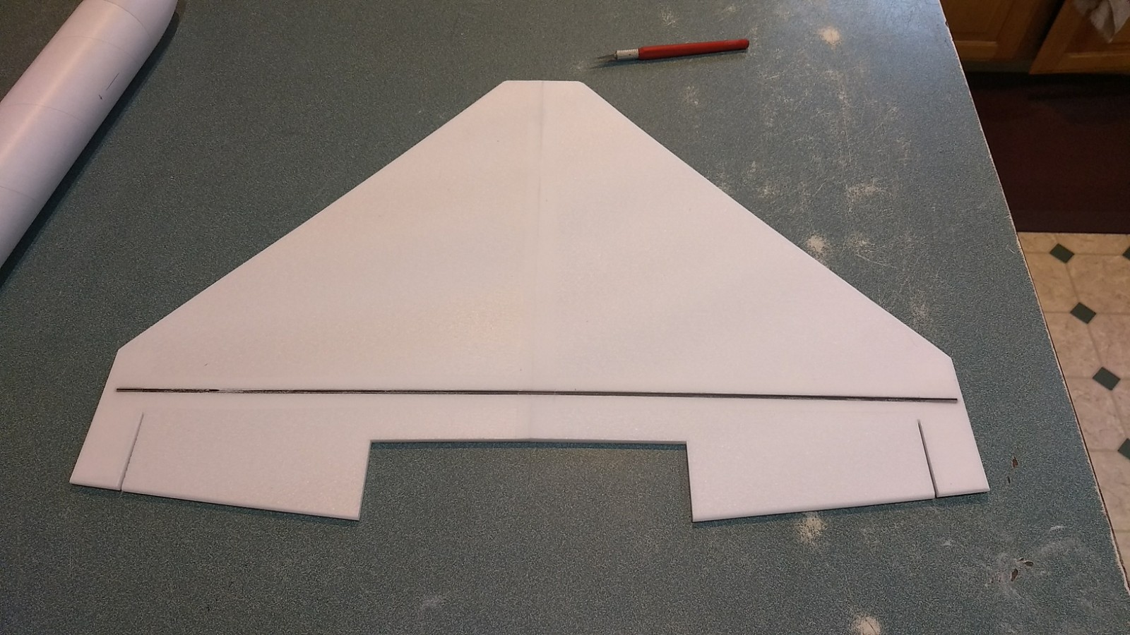
- Glue center joint and glue in spar, then tape over spar and center joint.
-
- Wing centered and installed
-
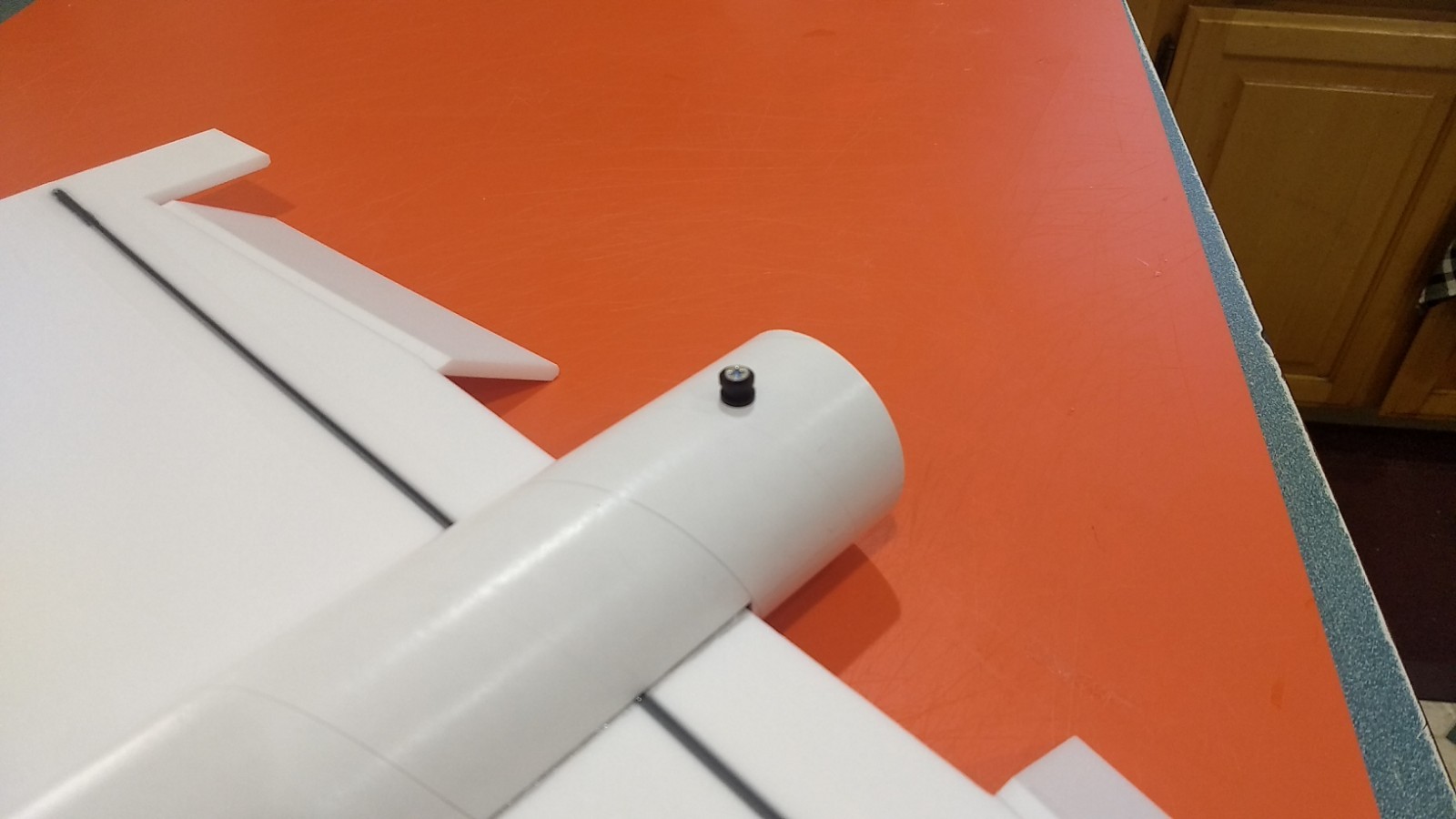
- Install the front and rear rail buttons
-
- Cockpit and tail pieces
-
- Fin glued into upper nacelle.
-
- Fin installed into upper nacelle
-
- Rear view of upper nacelle and fin installed
-
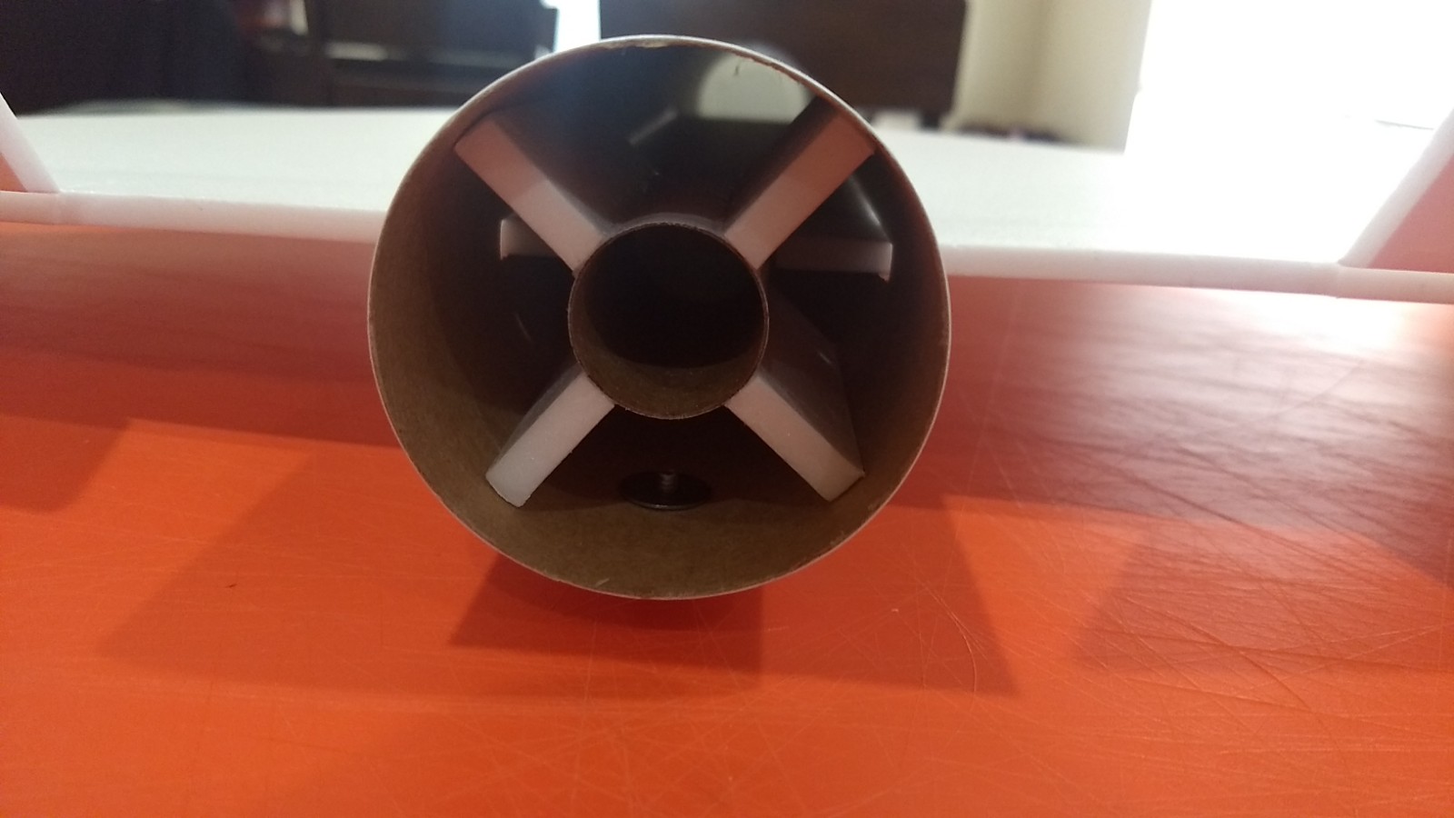
- Install the motor mount, note it is at a 45 degree angle to inset into the wing recess, it will be inset about 1/2″ from the rear of the body tube.
-
- glue the cockpit into the front of the nacelle and onto the body tube.
-
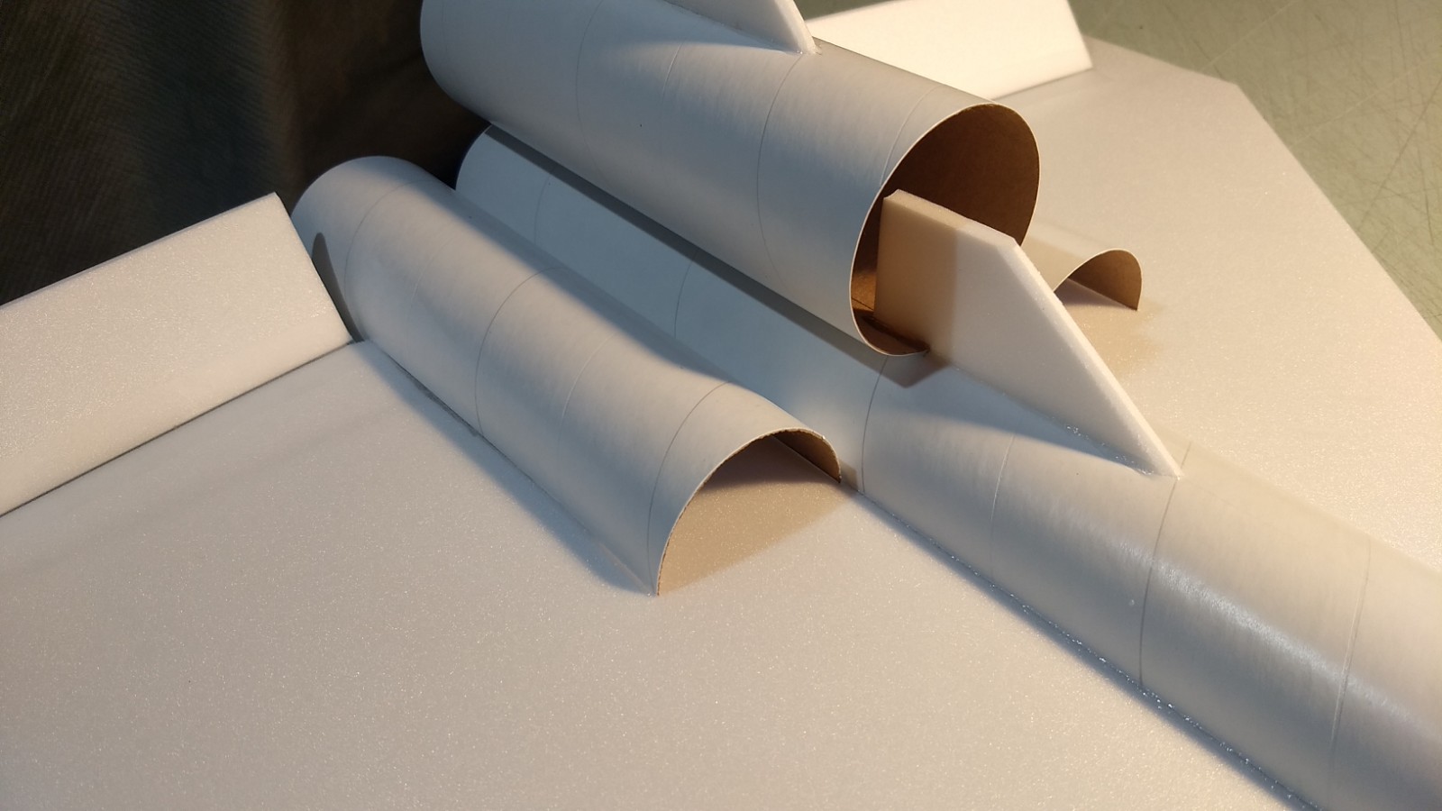
- Install the two side nacelles.
-
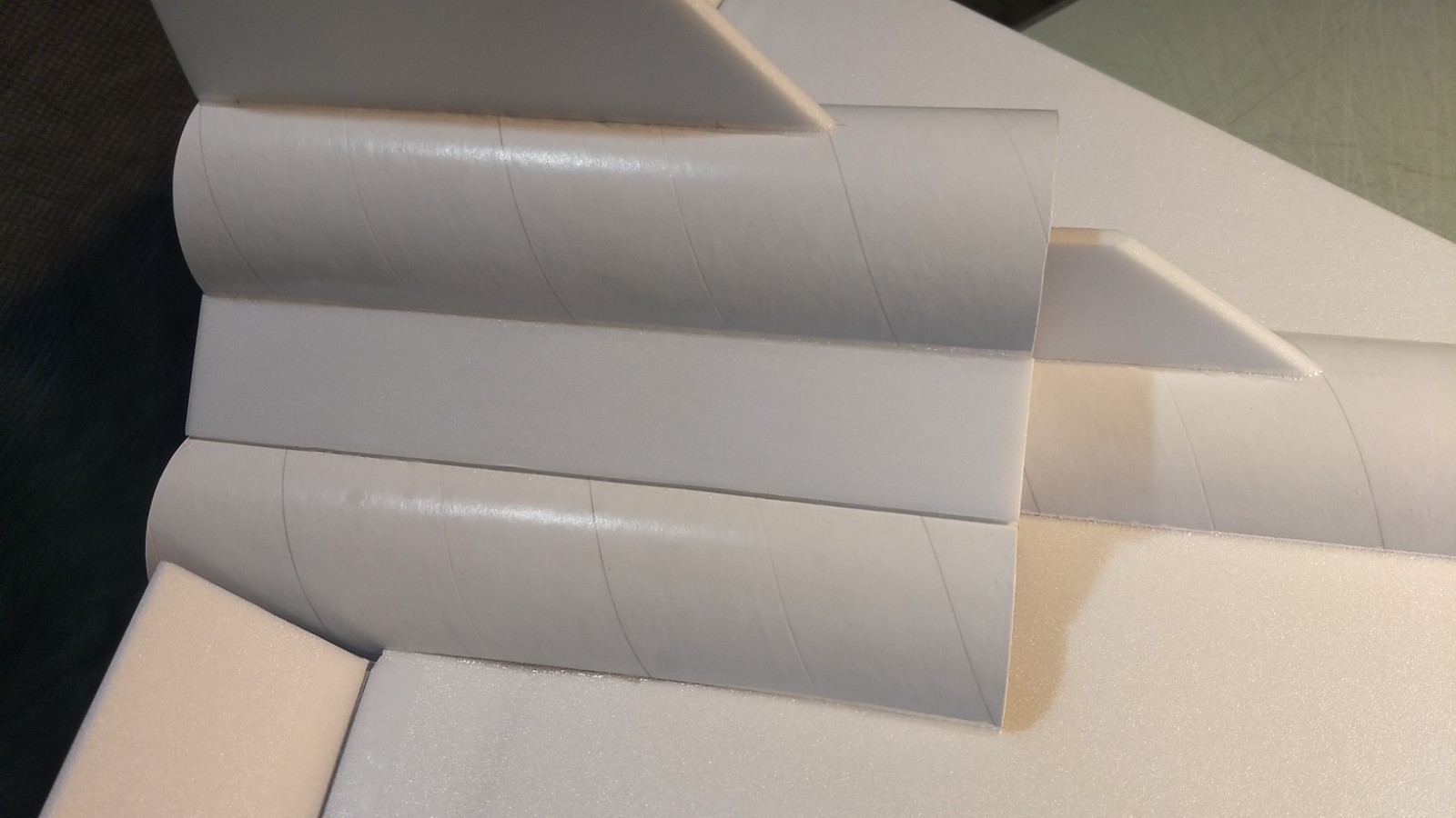
- Add the upper filler plate between the nacelles on both sides
-
- Add the lower filler plates between the body tube/nacelle on both sides.
-
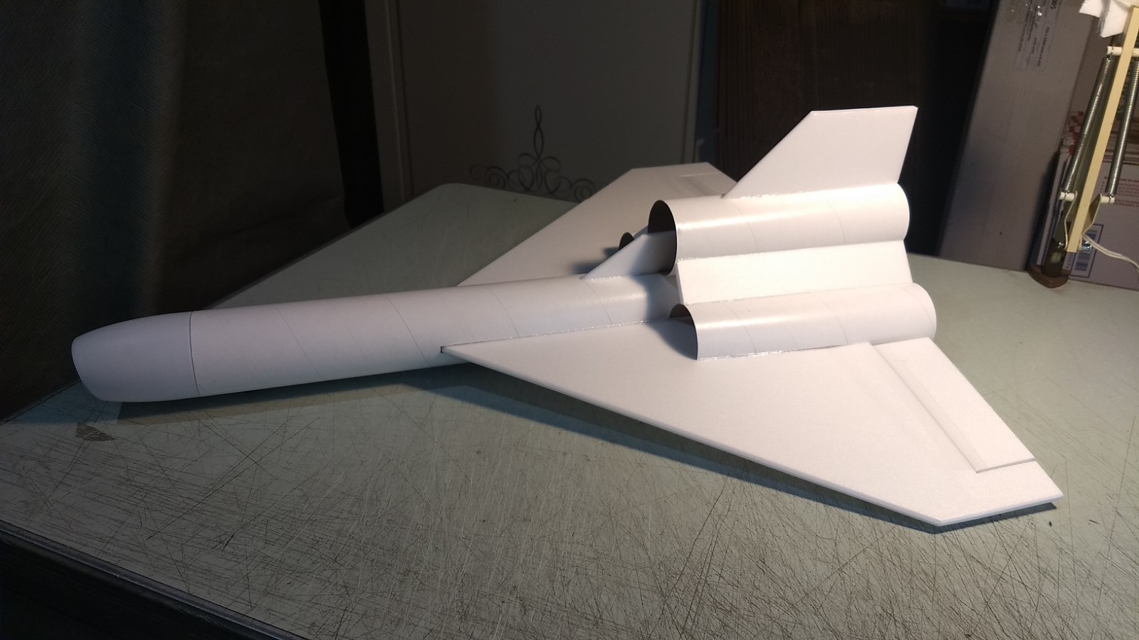
- Airframe completed ready for radio installation
-
- upper wing outline drawn
-
- lower wing outline drawn
-
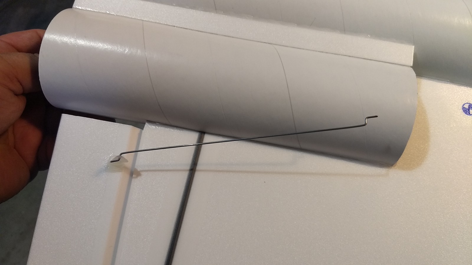
- glue the pushrod/horn on each side
-
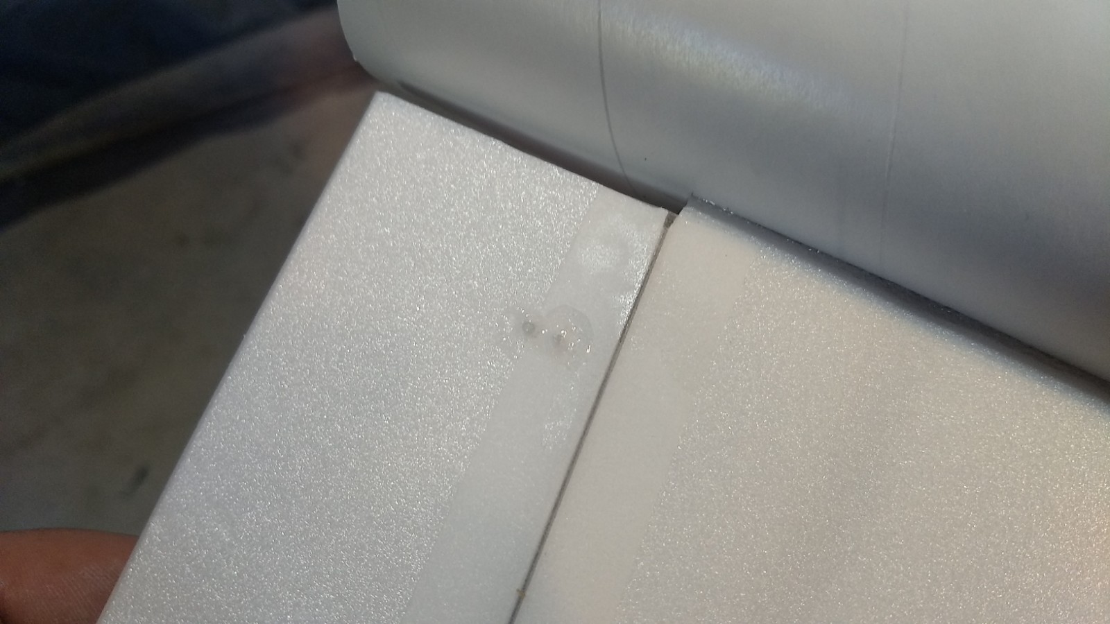
- Add glue to the top of the horn prongs to lock them in place.
-
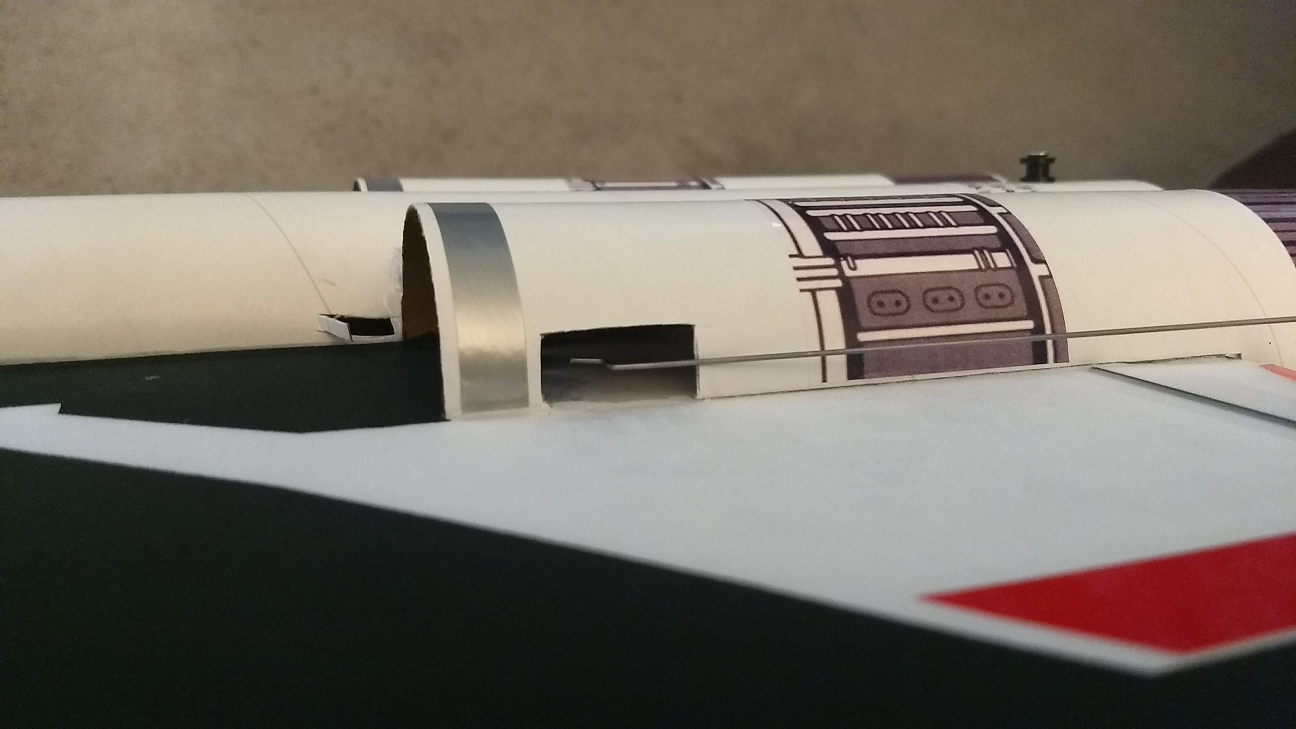
- Servo pocket and servo wire slots cut in nacelle and fuselage
-
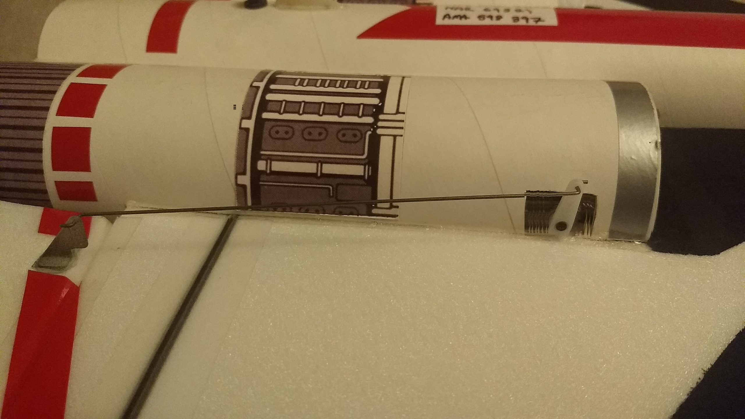
- Servo installed
-
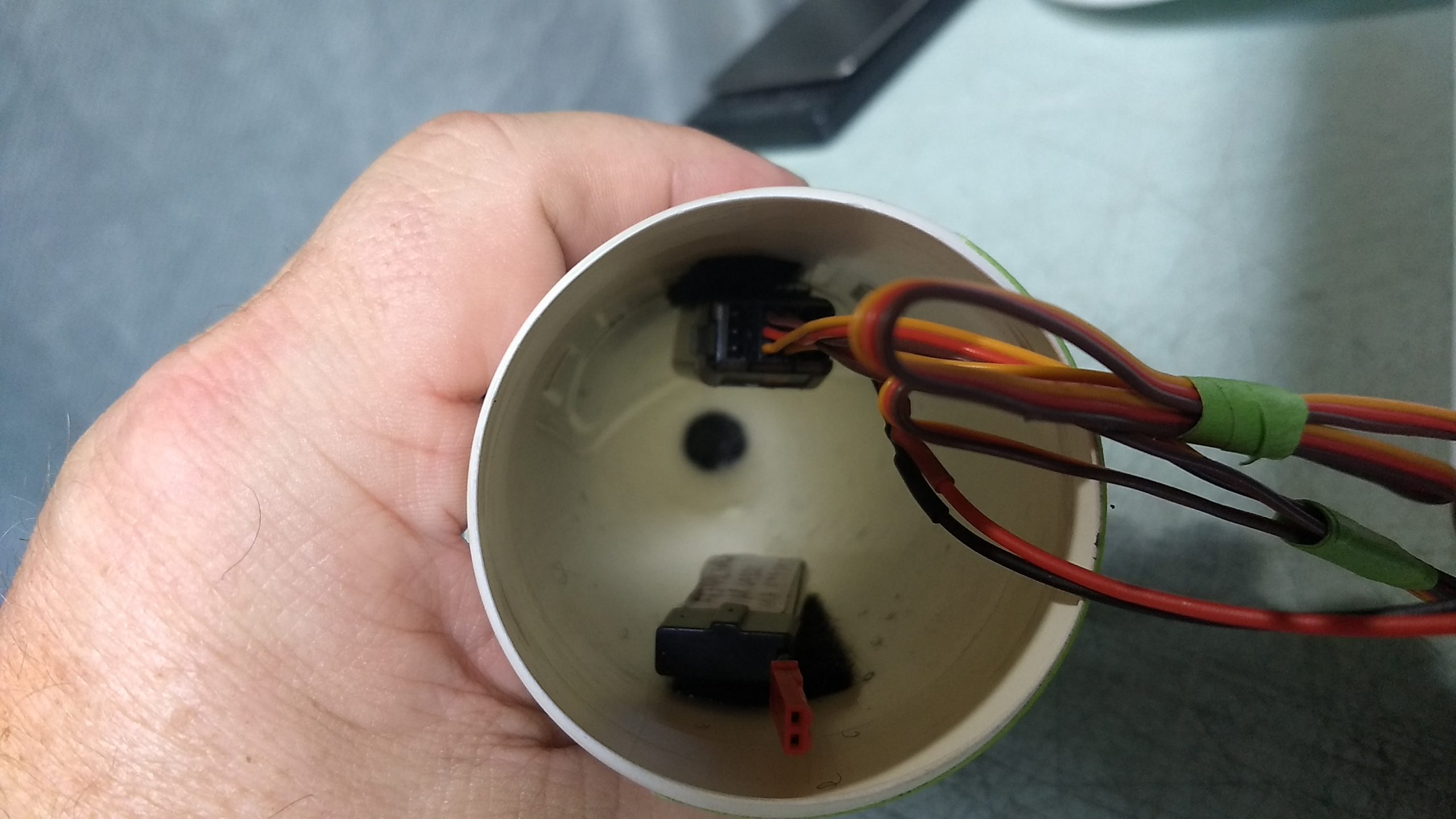
- attach the receiver and battery inside the nose cone with included velcro.