The Invader RC Rocket glider kit is an upscale/modification of the original Estes 1965 boost glider. It removes the dihedral to make a stronger wing and has a simple straight motor pod pylon. It comes with a plastic nose cone and 6mm depron wing and tail surfaces. The vertical stabilizer slots are pre-cut. Elevons are pre-hinged and spar is pre-installed. Comes with rail buttons. Construction and radio install is very simple. 19″ wingspan, 26″ length 5.75-6.1 oz ready to fly. For 18mm Reloadable C3.4T and D2.3T composite rocket motors only. Please refer to the General information for all kits tab above, then read these instructions completely before starting assembly.
CG location for rocket flight: 4 7/8″ rearward from the front of the wing at the center with an EMPTY motor casing and battery in place.
Welcome to the world of rocket boosted radio control gliders. This is not a model for a novice RC pilot, but anyone who is comfortable with RC flying of a medium speed model should be fine. Read through the instructions, look at the photos and be sure you understand the step before commiting to cutting or glue.
Identify all pieces, the kit should contain:
1 wing taped together
1 Nose Cone
2 pushrods/horns
2 vertical stabilizers
1 18mm mmt
Left and Right pylon
Velcro(for battery and rx/bec attachment)
2 Rail buttons with t nuts/screws
4 plastic rail button support disks
blenderm tape
Lead weight
Spare foam (for testing paint, glue, and sanding the edges to see how it behaves)
Notes before starting:
Foam safe CA+(Bob smith super gold + is good) is the only glue recommended for construction. You will also need foam safe accellerator to set the glue.
Assembly:
- Glue the taped wing joint and lay flat to set.
- Use 3m-77 spray or CA to glue the left and right pylon halves together, they are marked.
- You may use 220-320 grit sandpaper and a sanding block to slightly round the edges of the foam wing I used a straight edge and an exacto to put a bevel on the leading and trailing edges of the pylon and the stabilizers.
- Test fit then glue the pylon in place, it angles forward.
- Test fit then glue the stabilizers in place.
- Glue the two pushrods/control horns into the bottom of each control surface, the rods should be on the inside of the horn and angle inward toward the center.
- Put a bit of CA on the top of the control horn prongs to lock them in place.
- Glue the four styrene disks on the top and bottom of each pre-punched hole to support the rail buttons.
- Install the front and rear rail buttons at this time. The t-nut goes on the inside, then add a washer, collar and washer and secure with a screw. The rail buttons will be on the TOP of the wing.
- Glue the motor tube onto the pylon.
The basic construction is now complete.
Radio Installation
Note: Your radio needs to be configured for Delta mixing, this means that the servo arms will move the same direction during elevator stick movement and opposite for aileron stick movement. Connect your servos to the receiver one in the aileron connection and one on the elevator connection and apply power. Use a servo arm at least 9/16” long and with holes small enough that there won’t be slop with the pushrod wire when installed. I use the hole furthest out on the servo arm, to maximize movement. On some servos there are a long two-ended servo arm, you can trim off one end if needed to get sufficient length. Zero out any trim settings on the transmitter. The model once the motor has burned out is nose heavy and flying wings lose pitch authority when nose heavy so you want as much up elevator travel for trim/flare as possible.
- Connect a servo to each pushrod. If the pushrod is too tight, you can use twist an X-Acto knife in the servo arm hole to make it larger, but be careful and do not make it too large. Once connected, tape each servo in place so that the control surfaces are centered. Look at the model from the rear. Moving the transmitter stick back(up elevator) should move both elevons up. Moving the transmitter stick to the right should move the right elevon up and the left elevon down. If you can’t get the servo reversing to give you the right polarity try swapping aileron/elevator inputs to the receiver or turning the servos over and swapping the servo arms to the other side of the output shaft. If that is correct, continue.
- The servos are attached by directly gluing the servo to the wing with foam safe CA+. Double back servo tape can loosen over time and with exposure to heat, I prefer to glue the servo in place.
- With the radio still on, put a moderate amount of glue on the servo, being careful not to get any near the output shaft, and set it in place on the wing in the pocket you just cut, keeping the control surface centered. Do the same to the other side. Make sure the glue is set before continuing.
- Make sure the control surfaces are centered, use trims if needed. Now measure the control surface movement. Full elevator movement should be 1/2″ to 5/8” in each direction, aileron movement should be 3/8″ to 1/2″ in each direction.
- If you have a flap/elevator mix you can program up elevator to a switch setting. The model needs approximately 1/8″ of up trim for BOOST and zero trim for glide! If you can’t set the up elevator trim to a switch on your radio you’ll have to manually put in boost and glide trim which is hard to do while flying the model. You can also use flight modes to set different launch and glide elevator trim settings and control those via a switch.
- Tape the servo wires down using the supplied blenderm tape.
- I can only recommend testors/model master enamel spray or Krylon Short Cuts small enamel spray cans at this time, others I’ve tried damage the foam surface. I recommend flat colors as they dry faster and the surface imperfections of foam aren’t as noticable. Balance the model after painting as it adds weight. Use the pictures as a rough guide for painting. I just used vinyl trim on my model to save weight.
- Install your receiver and battery at the very front bottom of the wing using the supplied velcro.
- Install but do NOT glue the nose cone in place.
- Insert an EMPTY motor casing into the motor mount against the nose cone shoulder.
- Support the model at the balance point indicated for boost. I use two pencils with the eraser pointed up and held in place with a small hand vice. Place the model upside down on the pencil erasers on the balance point indicated above.
- Use some of the included lead weight as far forward into the tip of the nose to balance it, as needed. Once balanced, glue the lead weight in place so it does not shift during flight. Then glue the nose cone into the front of the motor tube. Do not try to fly the model too nose or tail heavy. Remember, a nose heavy model flies poorly, a tail heavy model flies once. My model did not need any nose weight for correct balance.
Flying: See the General Instruction link at the top for flying instructions. Be ready on the first few flights to keep the model straight till you have the trims set perfectly for boost and glide.
On this particular model due to the high mounted motor it will tend to pitch forward a bit off the rail but then straighten out for boost. Once the motor stops burning, due to the slight up trim needed for boost, the model will want to pitch up at burnout and do a little flip. To avoid this, before burnout try to level slightly and flick in the glide trim which should be zero uptrim. When loading the model on the rail for flight, put the motor igniter wires toward the top of the motor and tape in place, this will help prevent exhause gasses from blowing down the wires and burning the pylon. I have a bit of scorching from one flight where I had the wires on the bottom, but the rest have been fine once I put the wires on top. I put a bit of vinyl trim on the top rear of the wing to prevent any exhaust soot from getting it dirty and preventing the rail from getting it dirty.
-
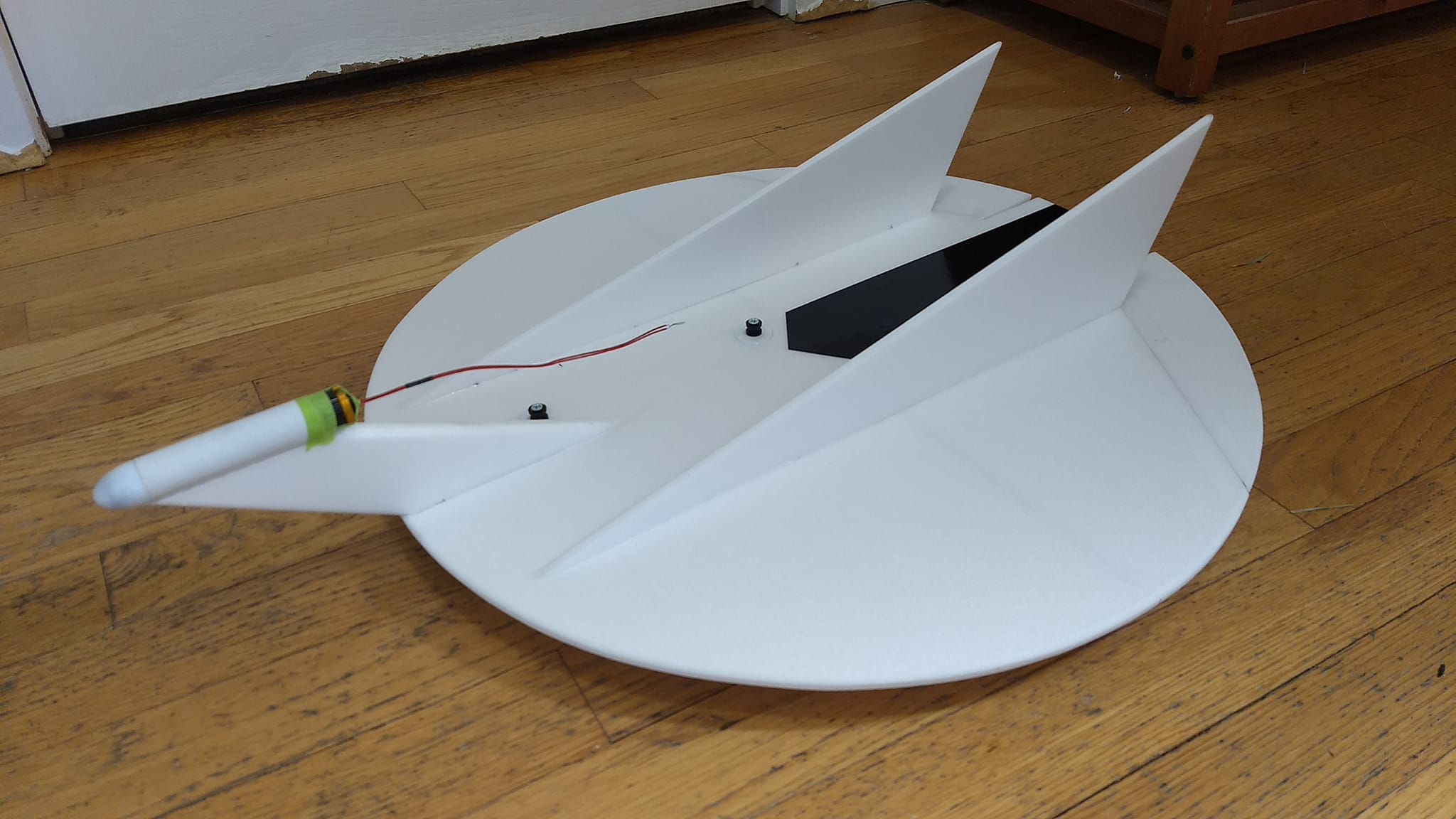
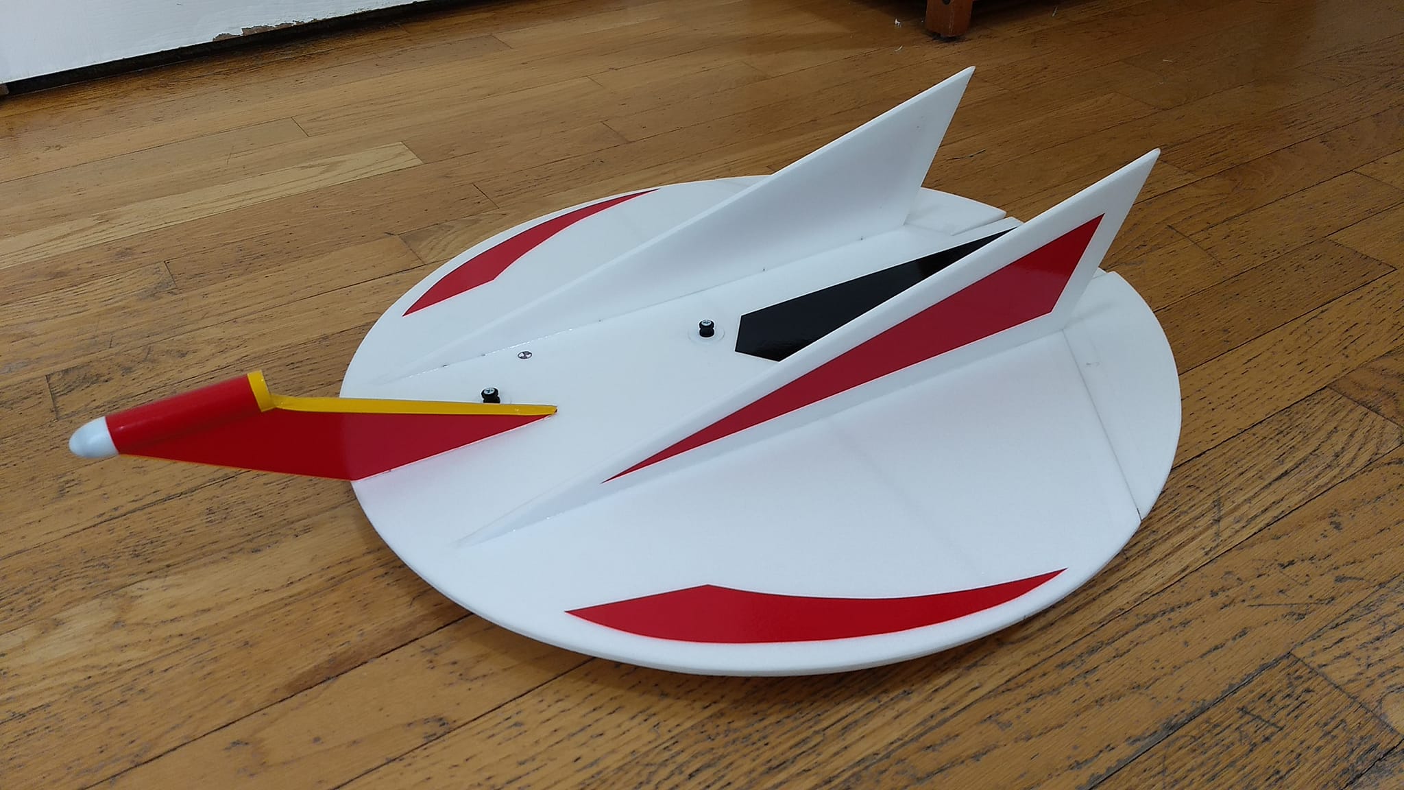
- Completed model
-
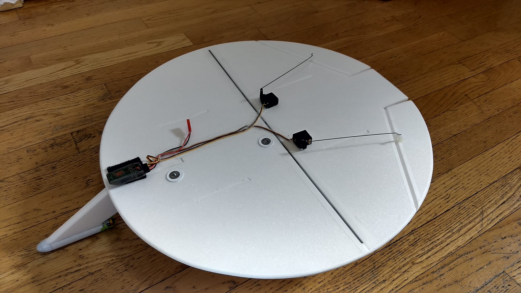
- Bottom showing receiver, battery and servos
-
- Ready for test flight
-
- Custom vinyl markings applied.