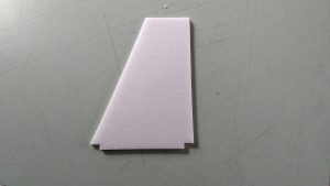
**Note, these are the instructions for the initial production run kits, if your vertical stab looks like the below picture, follow these instructions:
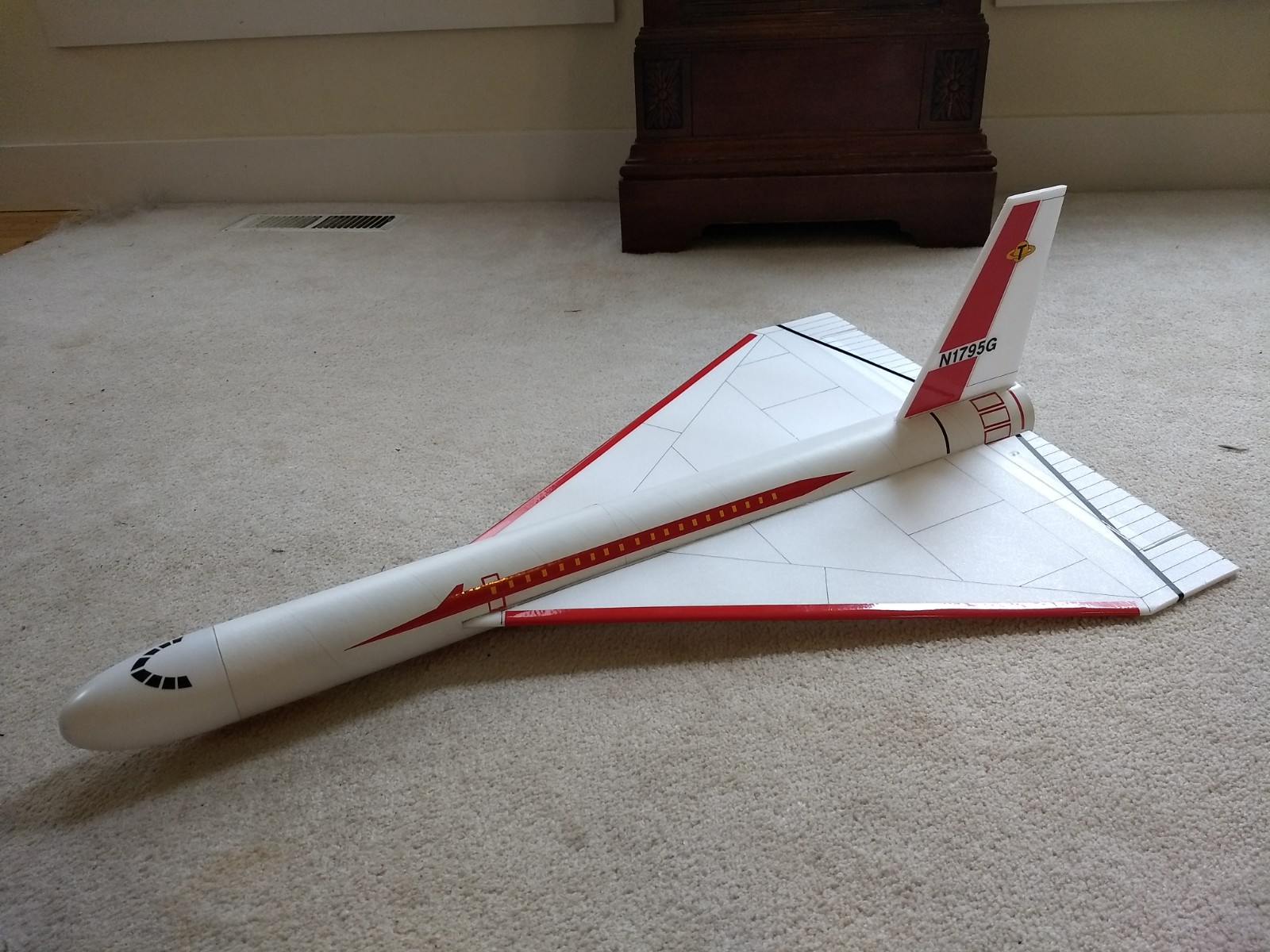
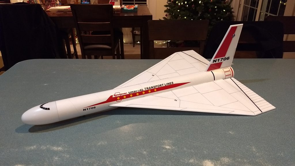
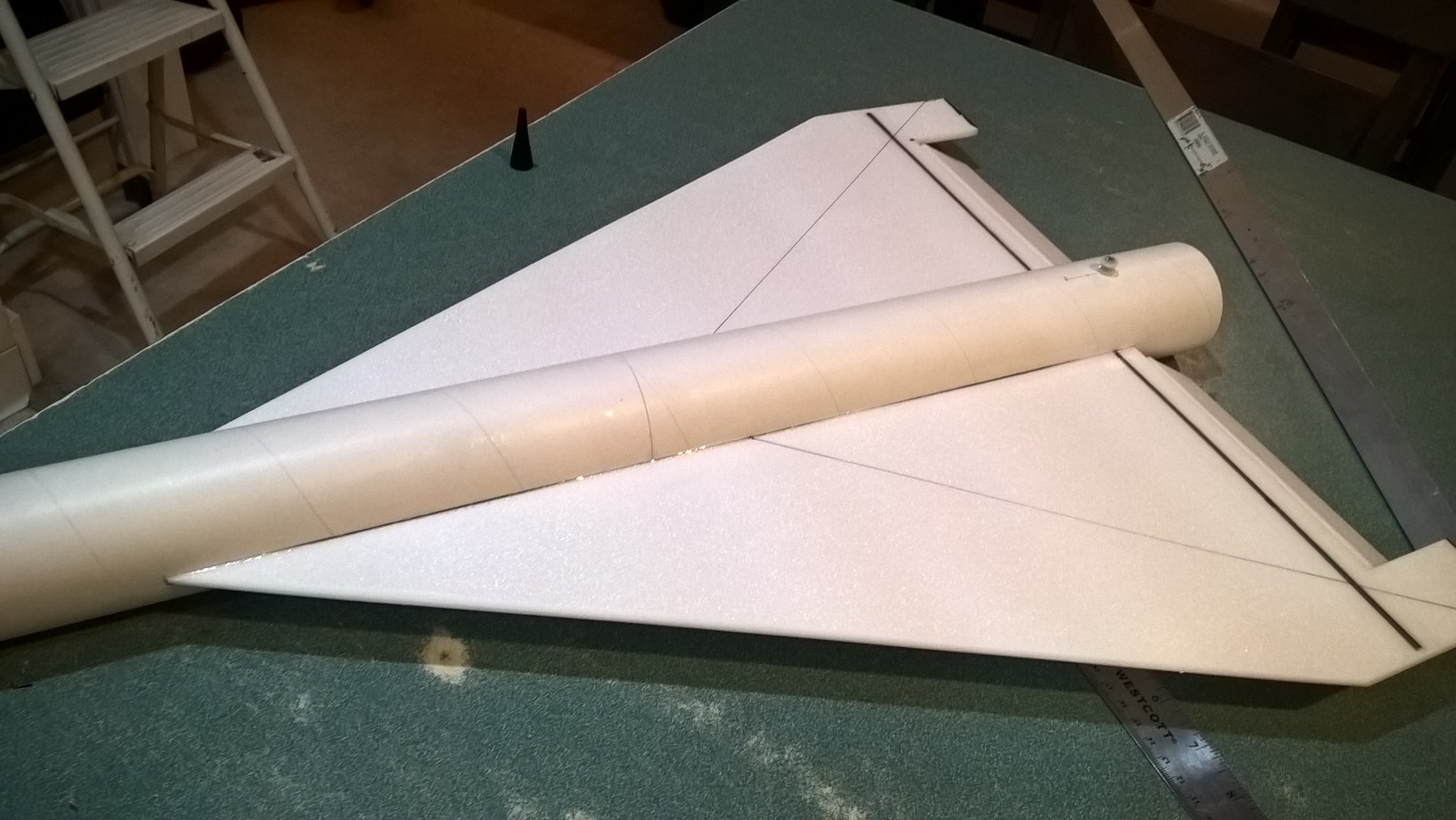
The Orbital Shuttle RC Rocket glider kit is based on Orbital Transport rocket glider kit from the 1960’s/70’s. It comes with a plastic nose cone, 2.6″ white tubing for the body, 5.5mm Model Plane Foam (MPF) wing and 6mm depron tail surface. Construction is very simple and takes about an hour and a half. The only hard part on this model is cutting the slot for the wing after you assemble the body tubes, however the slot locations are pre-marked for you. Please refer to the General information for all kits tab above, then read these instructions completely before starting assembly. CG location for rocket flight: 13” forward of the rear end of the body tube.
Welcome to the world of rocket boosted radio control gliders. This is not a model for a novice RC pilot, but anyone who is comfortable with RC flying of a medium speed model should be fine. Read through the instructions, look at the photos and be sure you understand the step before commiting to cutting or glue.
Identify all pieces, the kit should contain:
1 wing taped together
1 Nose Cone
1 wing spar(carbon fiber)
2 pushrods
1 vertical stabilizer
2 control horns
2 Body Tubes
Motor mount
4 13/16″ x 2.5″ wide strips to center the motor tube.
Velcro(for battery and rx/bec attachment)
2 Rail buttons with t nuts/screws or 1 Launch lug
2 landing skids
3M blenderm tape
Lead weight
Spare foam (for testing paint, glue, and sanding the edges to see how it behaves)
Notes before starting:
Foam safe CA+(Bob smith super gold + is good) is the only glue recommended for construction. You will also need foam safe accellerator to set the glue.
You may use 220-320 grit sandpaper and a sanding block to slightly round the edges of the foam if you prefer before gluing the wing and vertical stab in place. Do any sanding before assembly.
The thin tubing tends to flatten out after the slot is cut, so when you glue the wing in place you may need to pinch the body tube with your hand while the glue sets to keep it round and from bowing out in the middle. Once glued to the wing, it’s very stiff.
Assembly:
- Body Tubes. One tube will have a coupler pre-glued in place. Glue the other tube onto the coupler, make sure the small arrow marks are aligned on the two tubes, that will ensure the wing slot mark and rail button marks are properly aligned. Use any appropriate glue sparingly, as you will need to cut through the coupler to cut the wing slot.
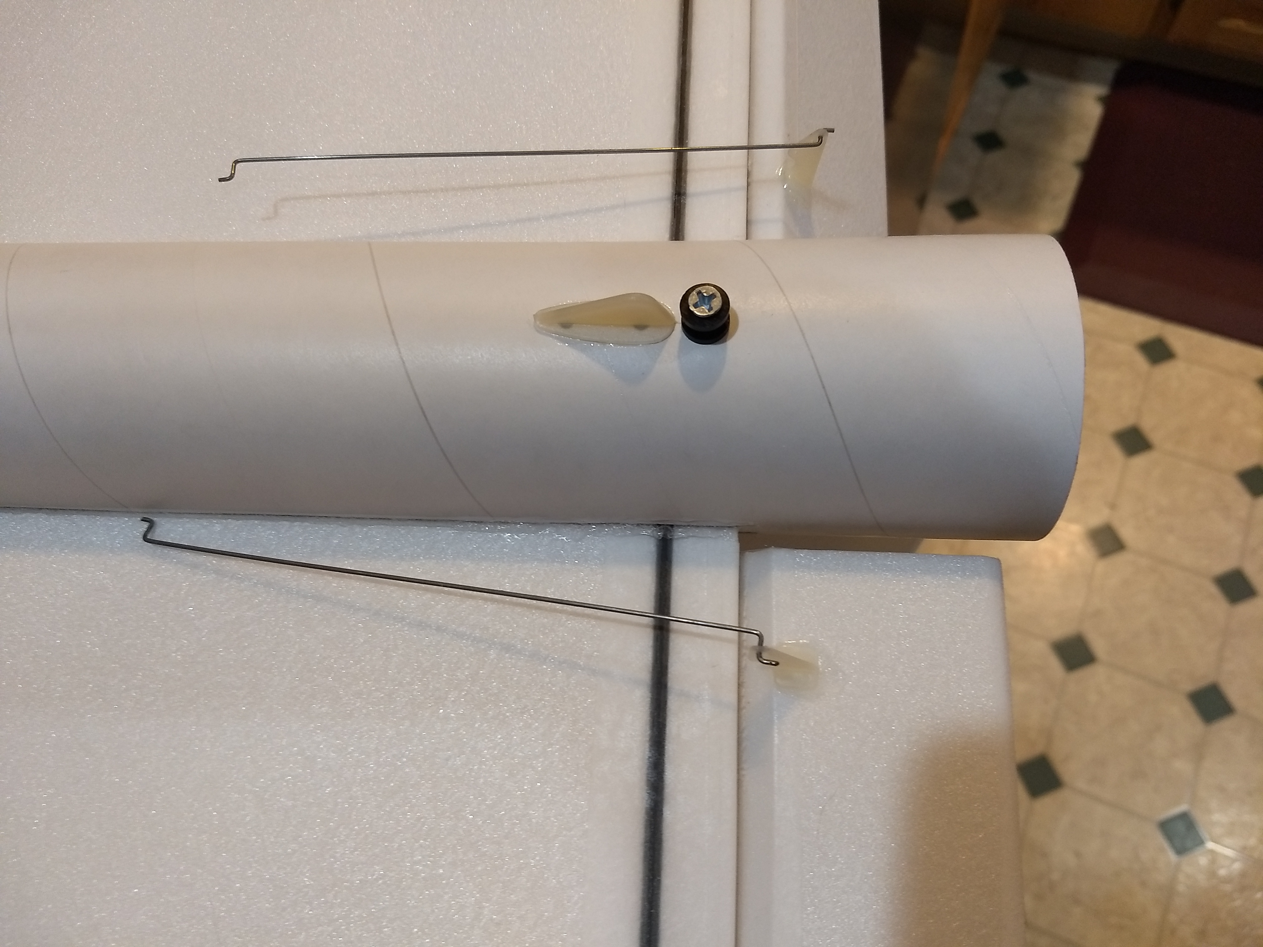
- Using an X-Acto, cut out the hole in the rear and front rail button locations marked on the bottom of the tubes to fit the t nuts. Insert the T nuts from the inside of the tube and install the T nuts, rail buttons and screws, don’t tighten them down really hard, just snug enough to not come out. Make sure they are aligned and don’t bind on the rail. The rail buttons are inset to the right depth so that they do not interfere with the vertical fin or nose cone shoulder. It may be helpful to set the t nut on a ruler, and insert it into the body tube, then press into the hole from the inside then start the screw and rail button pieces. It may be helpful to have someone hold the tube for you. Do this step now as it is not possible to do once the wing and vertical stab are in place.
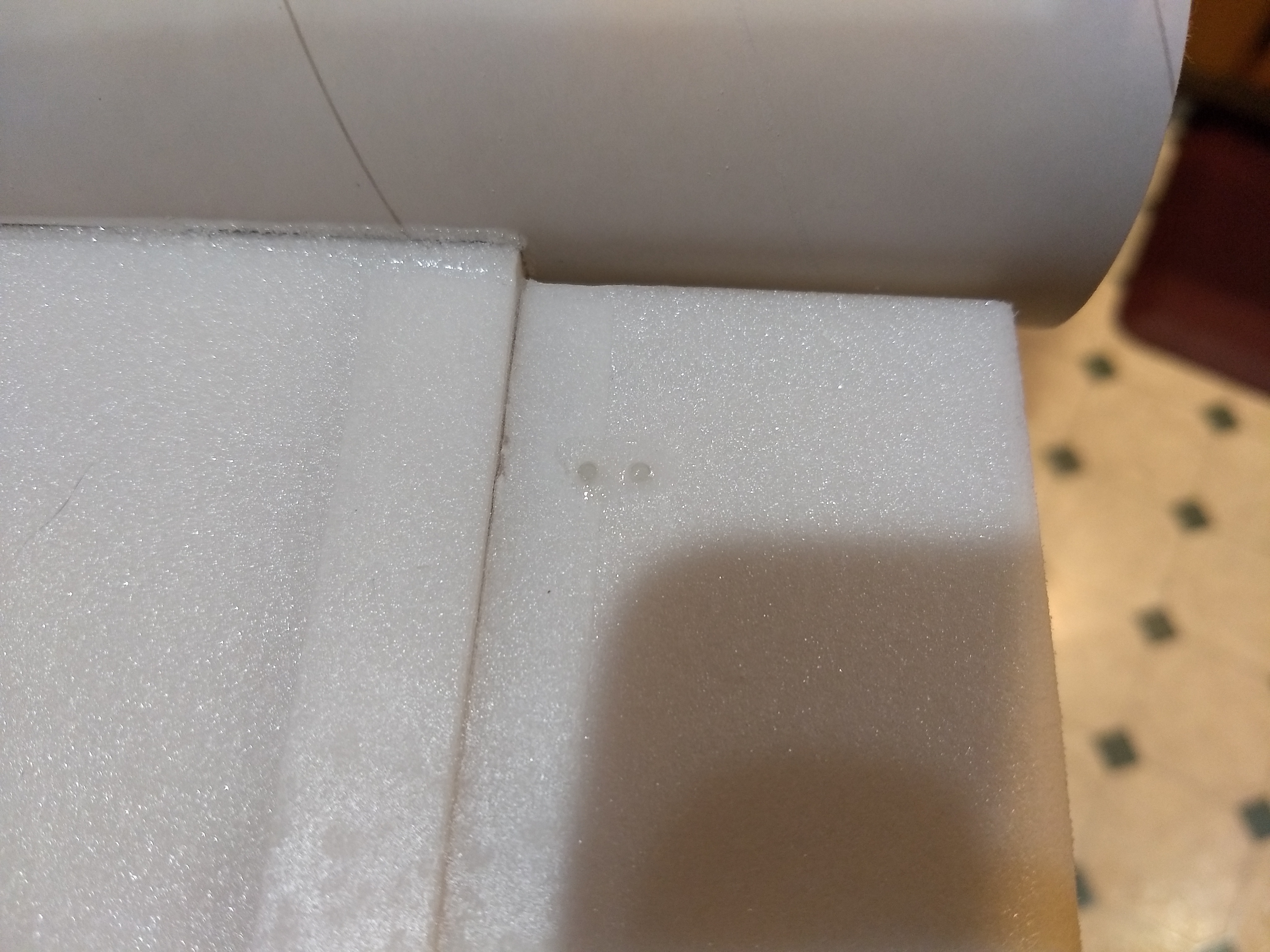
- Cut the slot for the wing once the coupler joint is dry. The front and rear portions of the wing slot are pre-cut for you, all you need to do is finish cutting through the coupler. Take your time, use a ruler or guide and make multiple light passes on each side before cutting through completely. ** Note the right wing slot has a little tab cut and folded up, this is to give enough room for the wing to be inserted and rotate into place, don’t remove this piece. (***Note early kits did not have the wing slot pre-cut, I found using a sharp X-acto, and a straight edge and make VERY light multiple passes to cut the slot, cut the front and rear portions first on both sides, then cut through the coupler as described above.
- Unfold the wing and apply CA+ to the taped joint, then flatten the wing to bond the joint.
- Glue the wing spar in the pre-slotted area on the bottom of the wing. Tape over the spar and the center wing joint with the included blenderm tape.
- Test fit the wing in the slot, insert it from the righthand side, if it is snug, sand or trim as you don’t want it to drag/damage the wing as you are inserting it. There is a tab at the rear that allows the wing to move backwards slightly as you rotate the wing in place. Once the wing is in place you can fold that tab down behind the wing and glue it in place. Center the wing in place at the front and rear and glue it in place using a fillet of foam safe CA+ the full length of the outer joint on the top and bottom. Make sure the wing is flush with the front of the wing slot. This tubing is very thin and will tend to flatten out and make the slot seem bigger than it is, expecially in the middle. The best technique I’ve found is to glue the bottom first. Start at the front and apply a fillet of glue on both sides of the tube, about 6-8″ at a time, and squeeze both sides in slightly so that the tube makes contact with the wing and then use accellerator to set the glue. Then do the next 6-8″ portion etc till you are at the rear. Make sure as you glue the rear that it is fairly round, you may need to squeeze the sides in slightly at the back. Then turn the wing over and do the same thing.
- Installing the Vertical stab and motor mount
- Glue the four 2.5″ long foam strips evenly spaced around the motor tube and even with the front part of the tube that has the motor hook flush using foam safe CA+. These help center the motor tube in the body tube once you insert it into the vertical fin slot. Make sure not to glue to the motor hook. Exact spacing is not required, just eyeball it so that it looks close.
- Test fit the vertical stab into the slot in the body tube carefully. You may notice that the when you mount the vertical tail you may need to trim the slot slightly, I left it snug, trim if you think it needs it. Once the fit is right, glue the vertical fin into place, making sure it is perpendicular to the wing and straight along the body tube. Again, since the tube deforms around the slot, you may need to squeeze the tube in slightly from top to bottom to keep it straight and against the vertical stab on both sides. Apply a light filet to both sides of the vertical stab on the inside and outside of the body tube. The vertical tail may seem like it has some side to side movement due to flex in the lightweight body tube, however once you glue the motor mount in place and abut one of the tabs on the mount with the vertical fin tab it stiffens up.
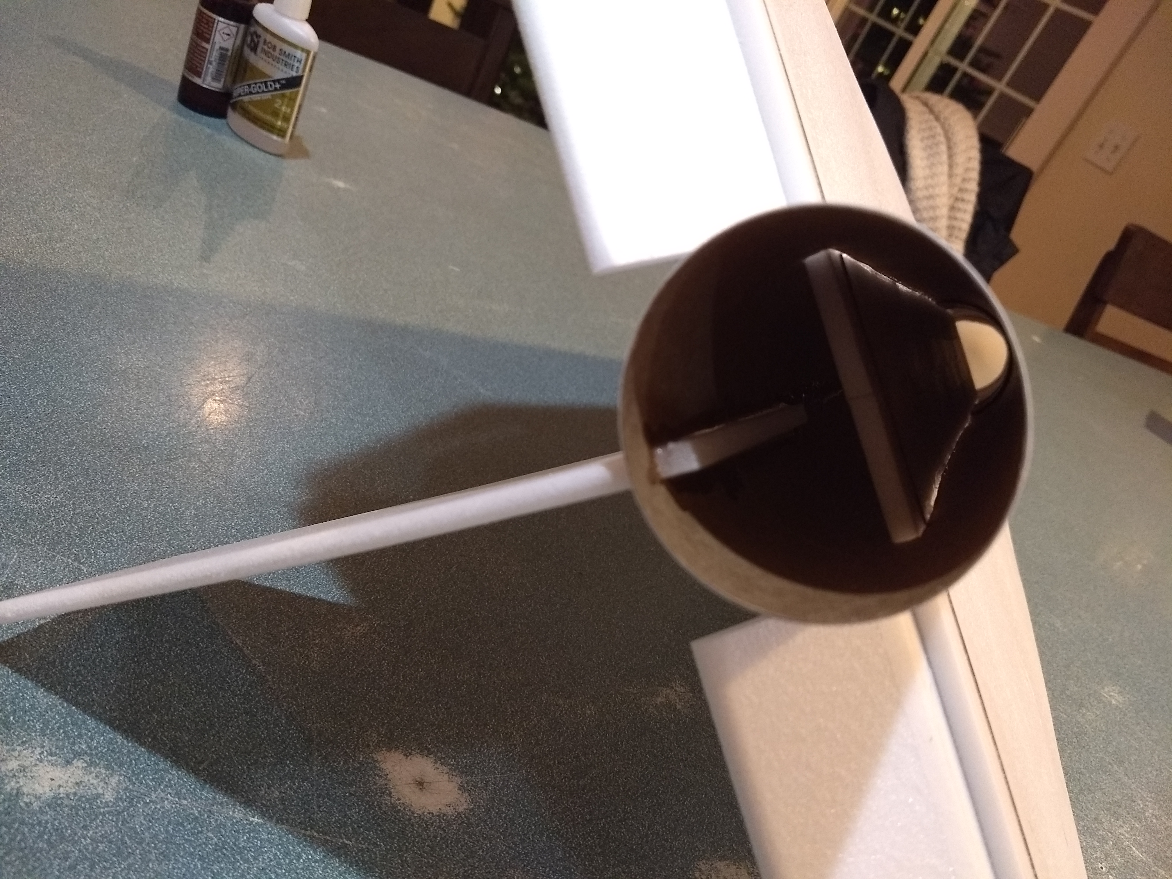
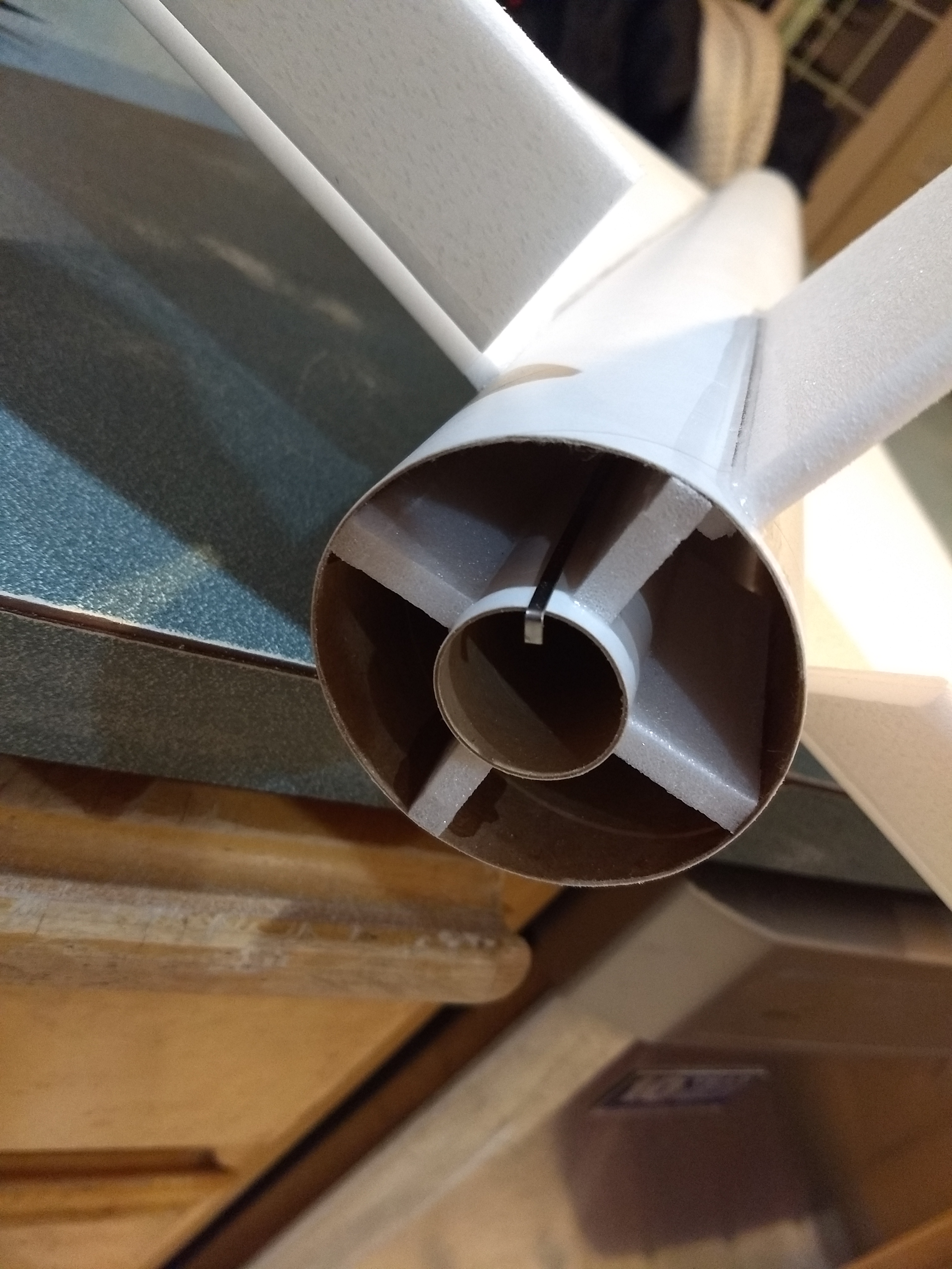
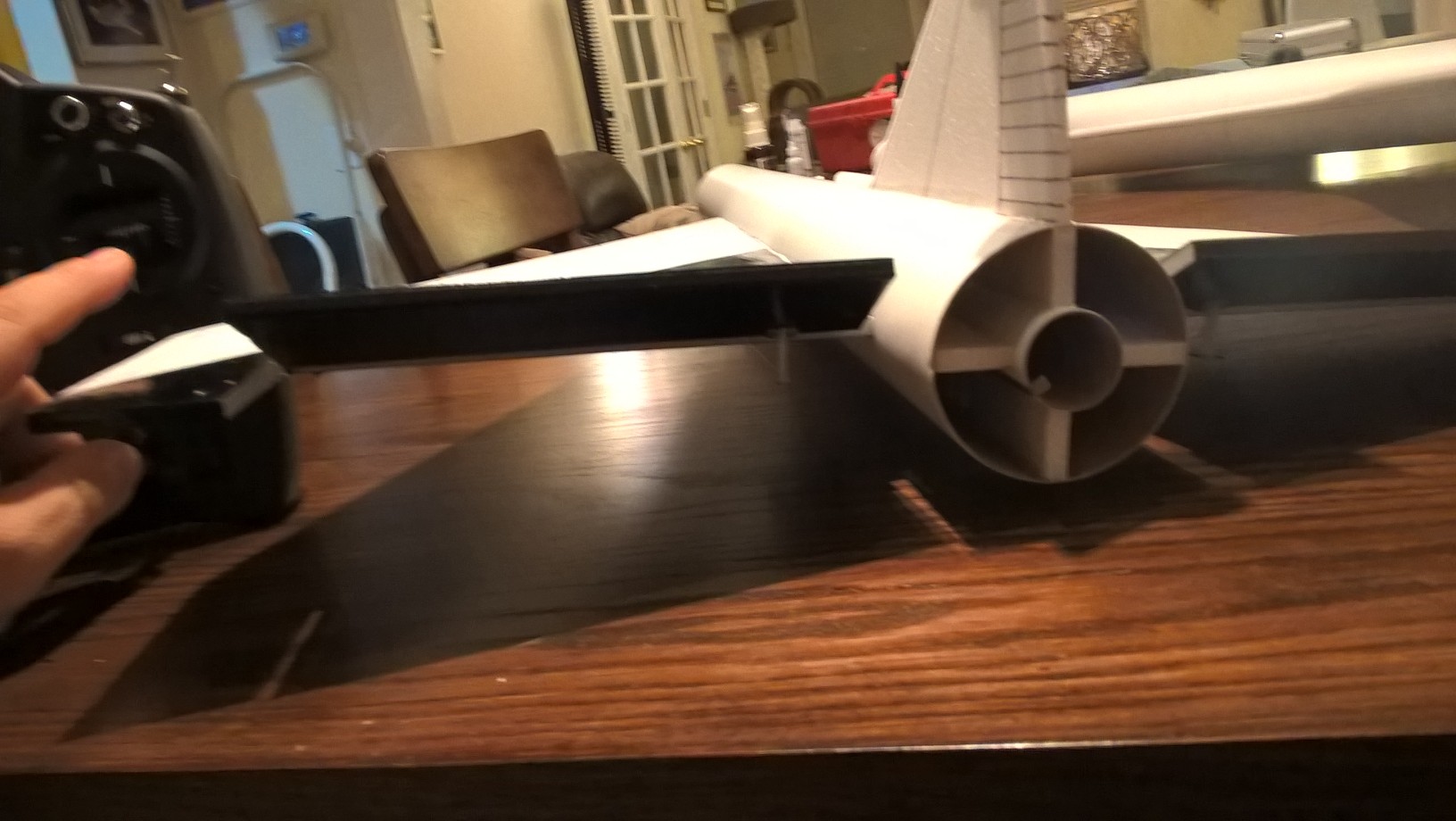
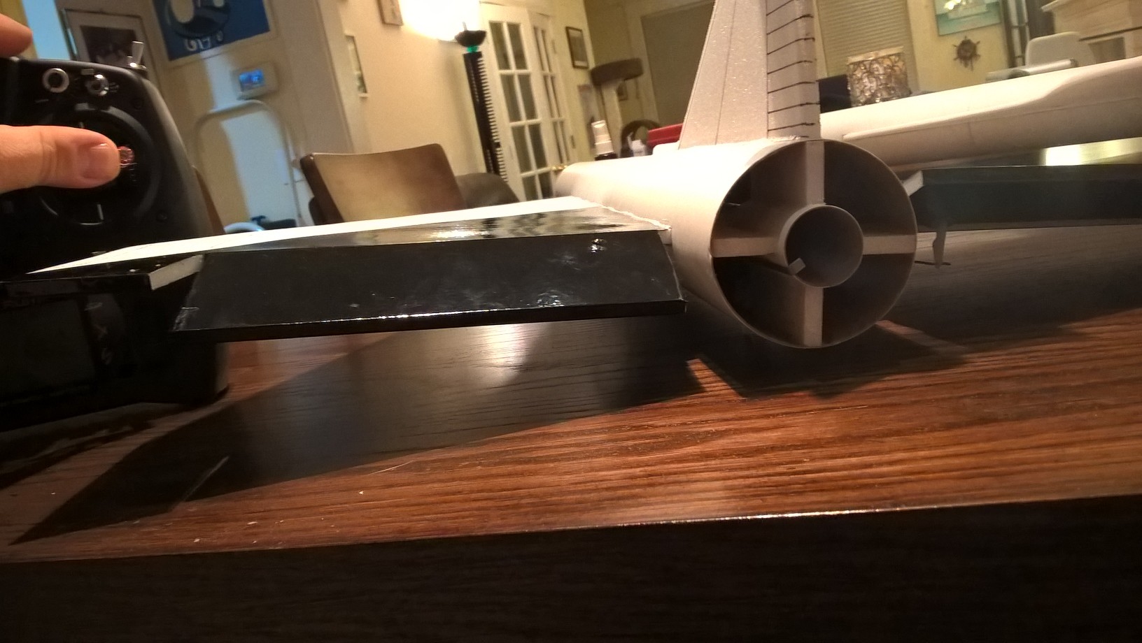
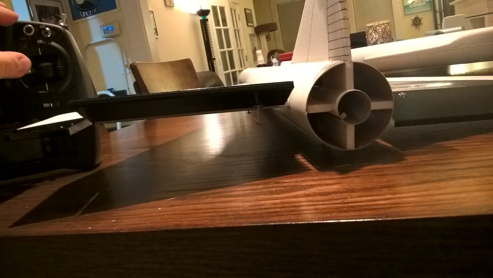
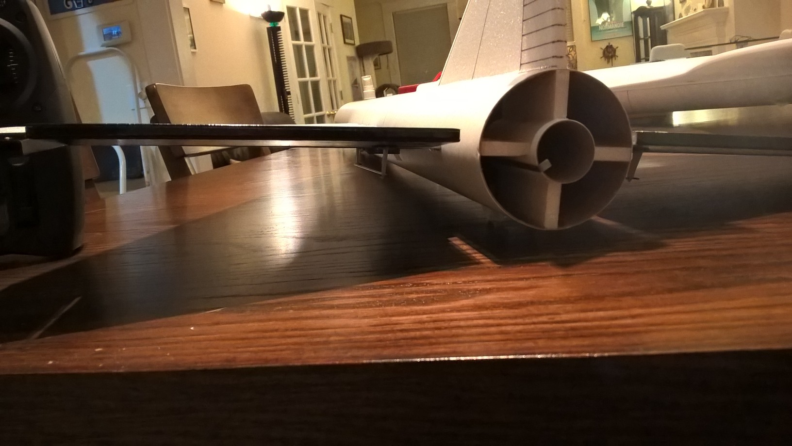
- Test fit the motor mount into the body tube. Make sure it fits, or sand the foam tabs lightly. The tabs you glued onto the motor tube will be rotated compared to the wing and vertical stab so that the motor mount clears the vertical stab tab that comes through the fuselage. Once inserted rotate the motor mount till one of the tabs contacts the vertical stab tab and and glue it against the tab. Glue the motor tube in place, it will stop against the wing, and the rear of the motor tube will stick out approx 1/4″ from the body tube. Put a fillet on each side of the motor mount tabs and fuselage, NOTE*** the motor hook is glued at the front, make sure you have the front forward when you glue it in place. You don’t need a lot of glue, as the motor can’t really go anywhere forward as it hits the fin tab at the front.
- Note that there should be two holes on each control surface, these should be approx 1″ from the inboard end of the control surface so that the control horn faces forward and the holes where the pushrod go through are aligned with the hinge line. If for some reason they are not there simply use small drill to make them through the the surface and the tape on the topside of the surface using the control horn prongs as a guide. Don’t make them oversized. Apply CA+ to each of the control horns and press them in place in the bottom of each control surface into the pre-made holes. Note the control pushrods go on the inside of each control horn nearest the body tube The holes face forward and the pushrod should be closest to the body tube. Apply a fillet around the control horn and the top of the prongs on the top of the wing.
- Install a landing skid just ahead of each rail button. Use a drill or tool to make starter holes for the prongs. Make sure they are aligned with the buttons and don’t drag on the rail, these help prevent button damage when landing. Use CA+ to glue them in place. Make sure the forward rail button prongs don’t interfere with the nose cone shoulder.
The basic construction is now complete.
Radio Installation
Note: Your radio needs to be configured for Delta mixing, this means that the servo arms will move the same direction during elevator stick movement and opposite for aileron stick movement. Connect your servos to the receiver one in the aileron connection and one on the elevator connection and apply power. Use a servo arm at least 9/16” long and with holes small enough that there won’t be slop with the pushrod wire when installed. I use the hole furthest out on the servo arm, to maximize movement. On some servos there are a long two-ended servo arm, you can trim off one end if needed to get sufficient length. Zero out any trim settings on the transmitter. The model once the motor has burned out is nose heavy and flying wings lose pitch authority when nose heavy so you want as much up elevator travel for trim/flare as possible.
- Connect a servo to each pushrod. If the pushrod is too tight, you can use twist an X-Acto knife in the servo arm hole to make it larger, but be careful and do not make it too large. Once connected, tape each servo in place so that the control surfaces are centered. Flip the model right side up and look at it from the rear. Moving the transmitter stick back(up elevator) should move both elevons up. Moving the transmitter stick to the right should move the right elevon up and the left elevon down. If you can’t get the servo reversing to give you the right polarity try swapping aileron/elevator inputs to the receiver or turning the servos over and swapping the servo arms to the other side of the output shaft. If that is correct, continue.
- Flip the model upside down and supported. The servos may be attached to the model using double back servo mounting tape(not included) or by directly gluing the servo to the wing with foam safe CA+. Double back servo tape can loosen over time and with exposure to heat, I prefer to glue the servo in place. With the radio still on, put a moderate amount of glue on the servo, being careful not to get any near the output shaft, and set it in place on the model keeping the control surface centered. Do the same to the other side. Make sure the glue is set before continuing. Note** The servo wire should point toward the front of the model and the servo should be butted next to the body tube. Apply a fillet of glue around the servo/wing to help secure it and let it cure.
- Attach a 6″-12″ servo extension to each servo.You just need to be able to route the wire to the front of the tube to attach it to the receiver.
- Make a 1/8″ wide by 1/2″ long slot in the body tube on each side of the body tube near the servo and pass the wires through to the inside and toward the front. On my model I just made a U shaped cut, folded the cardboard forward, inserted the wire then folded the cardboard back over the slot/wire. I then glued the cardboard tab in place. See photo for more clarity.
- Attach the servo wires to the receiver and make sure they are going the right direction.
- Flip the model back right side up. Make sure the control surfaces are centered, use trims if needed. Now measure the control surface movement. Full elevator movement should be 7/8” in each direction, aileron movement should be 1/2″ in either direction. Since the model will be nose heavy, extra elevon movement helps to give sufficient authority during glide.
- If you have a flap/elevator mix you can program up elevator to a switch setting. The model needs approximately 1/4″ of up trim for glide. If you can’t set the up elevator trim to a switch on your radio you’ll have to manually put in boost and glide trim which is hard to do while flying the model.
- Use the included Velcro to attach the receiver insde the body tube just against the front of the wing. This allows you to be able to remove and replace the receiver if needed for repairs or for removing the servo wires.
- I attached the battery inside the nose cone on the shoulder with velcro.
- Insert your heaviest loaded rocket motor into the motor mount
- Support the model at the balance point indicated for boost. I use two pencils with the eraser pointed up and held in place with a small hand vice. Place the model upside down on the pencil erasers on the balance point indicated above. Use pieces of the included lead weight as far forward into the tip of the nose to balance it, or in the tail as needed. Glue the lead weight in place so it does not shift during flight. Do not try to fly the model too nose or tail heavy. Remember, a nose heavy model flies poorly, a tail heavy model flies once
- I can only recommend testors/model master enamel spray at this time, others I’ve tried damage the foam surface. I recommend flat colors as they dry faster and the surface imperfections of foam aren’t as noticable.
- You can use a black fine line sharpie to add panel lines if desired.
- If you choose to use the stickershock markings, after application use a hair dryer on hot to warm the markings and them push them down into the foam surface with your finger. The will really conform and stick down well.
- Re-install the receiver and battery
Flying: See the General Instruction link at the top for flying instructions. Be ready on the first few flights to keep the model straight till you have the trims set perfectly for boost and glide.
-
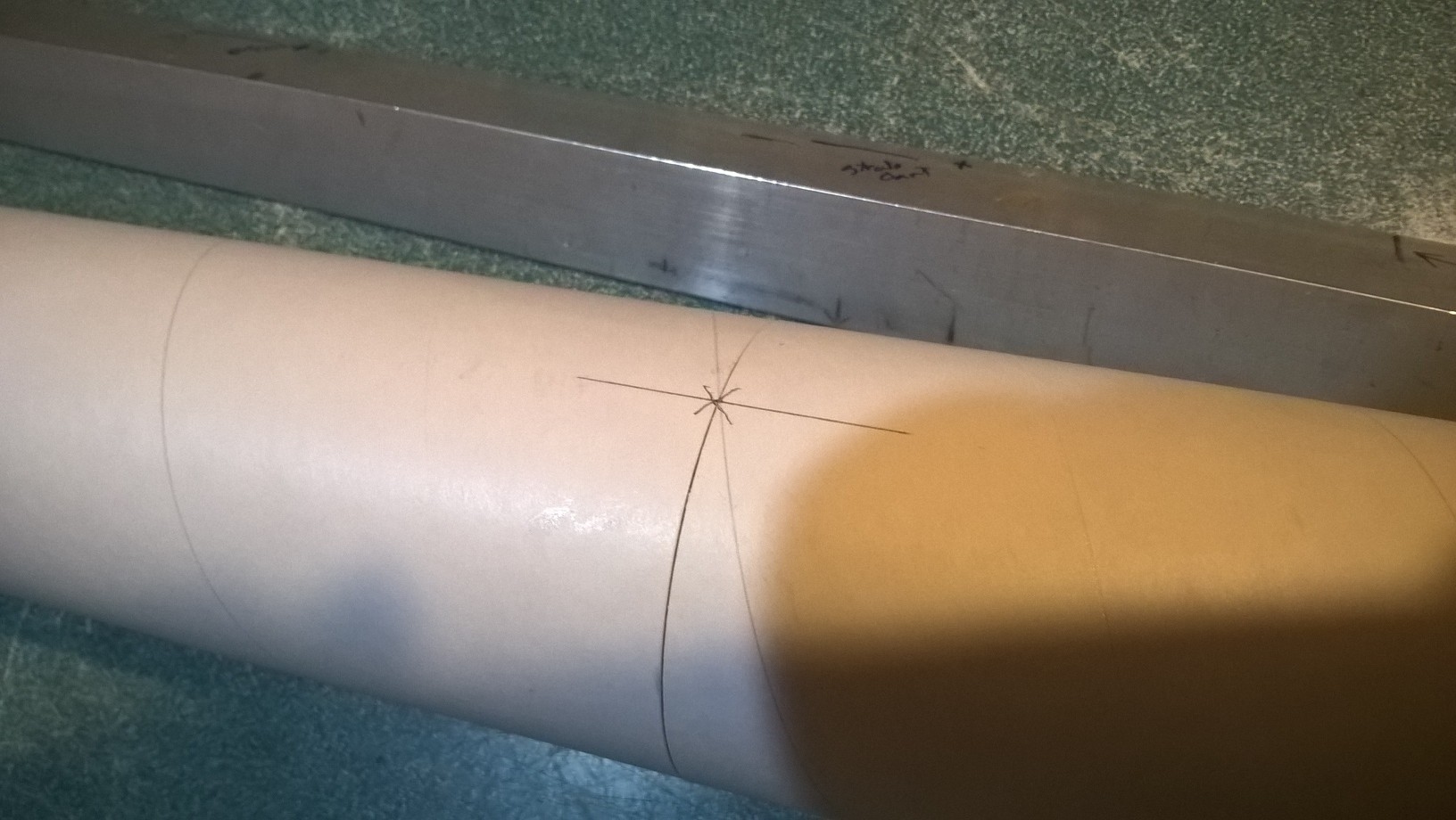
- Glue the two body tubes goether with the arrow lines aligned
-
- If not assembled for you, glue the four foam tabs onto the motor tube, evenly spaced and even with the front of the motor tube. If included glue the thrust ring to the front of the motor mount.
-
- assembled motor mount
-
- find the rail button circles on the bottom of the tube
-
- cut out the holes with an X-acto
-
- insert the rail button t nut from the inside and hole in place
-
- Insert the washer, collar and outer washer that makes the rail button and capture the with the screw.
-

- glue the wing joint
-
- Glue the spar in place
-

- then tape the spar and wing join with blenderm tape
-
- Note the wing slot has a tab pre-cut on the right side, leave this tab up, it allows enough room to rotate the wing into place, once the wing is in place, fold this tab down behind the wing and glue into place.
-
- Once centered, glue the wing in place, make sure the wing is even with the front of the slot
-
- Glue the tail in place
-
- Insert the motor mount and glue in place
-

- glue in the two skids just in front of each rail button
-

- glue in the two skids just in front of each rail button
-
- pushrods and control horns glue in place
-
- glue added over prongs in horns to lock them in place
-
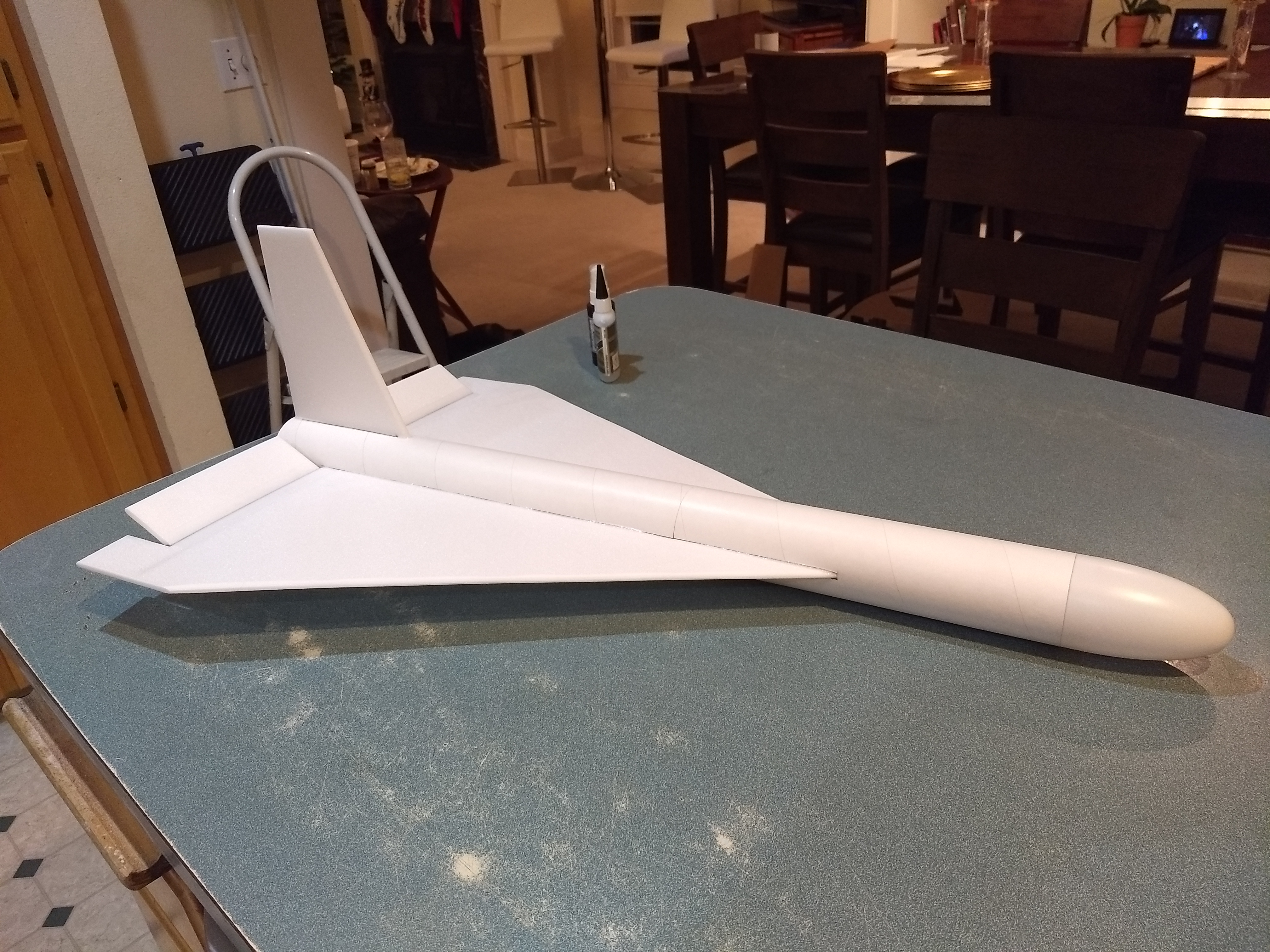
- Airframe completed
-
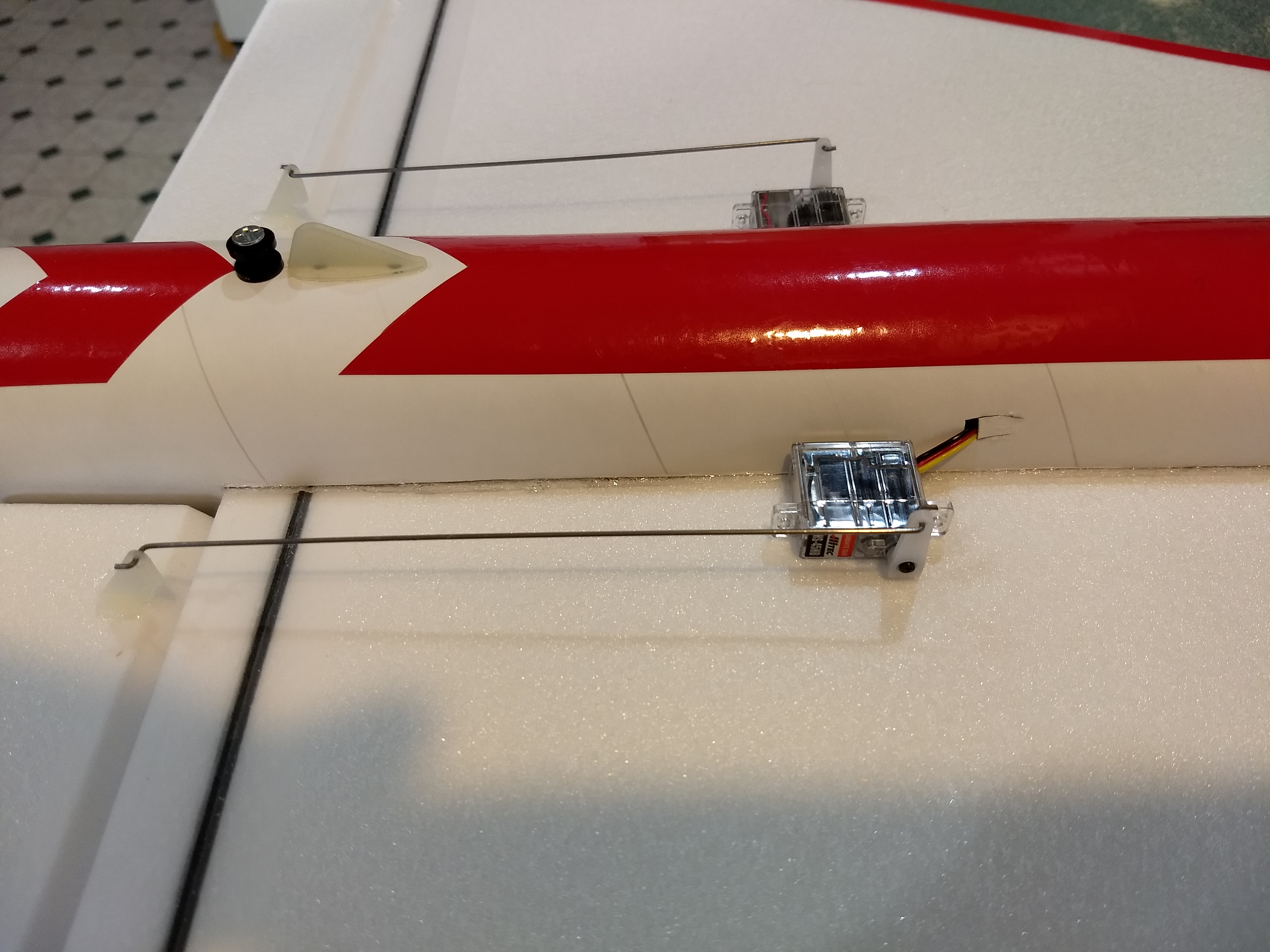
- Servos Installed
-
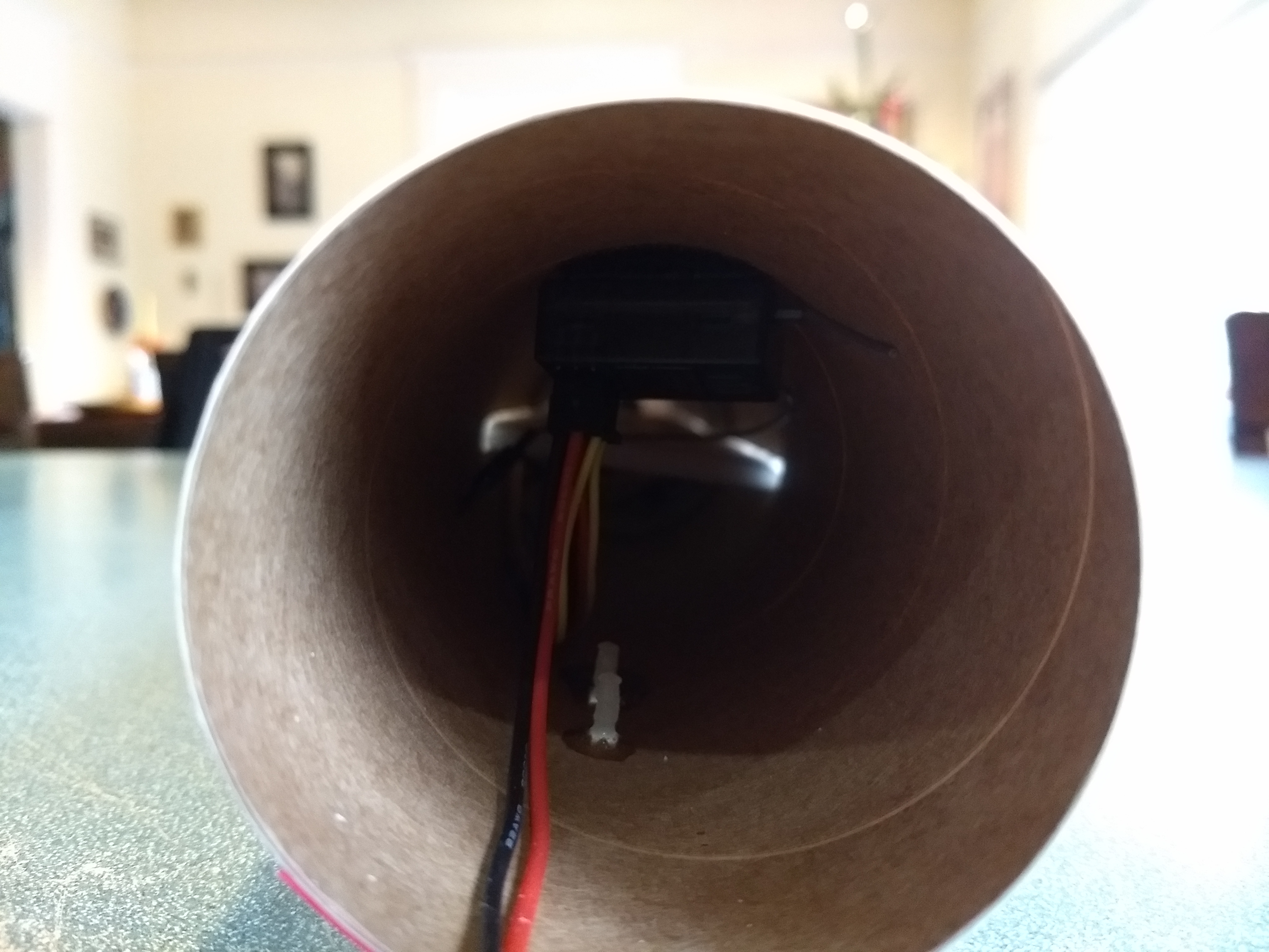
- Receiver velcro’d inside body tube at the top
-
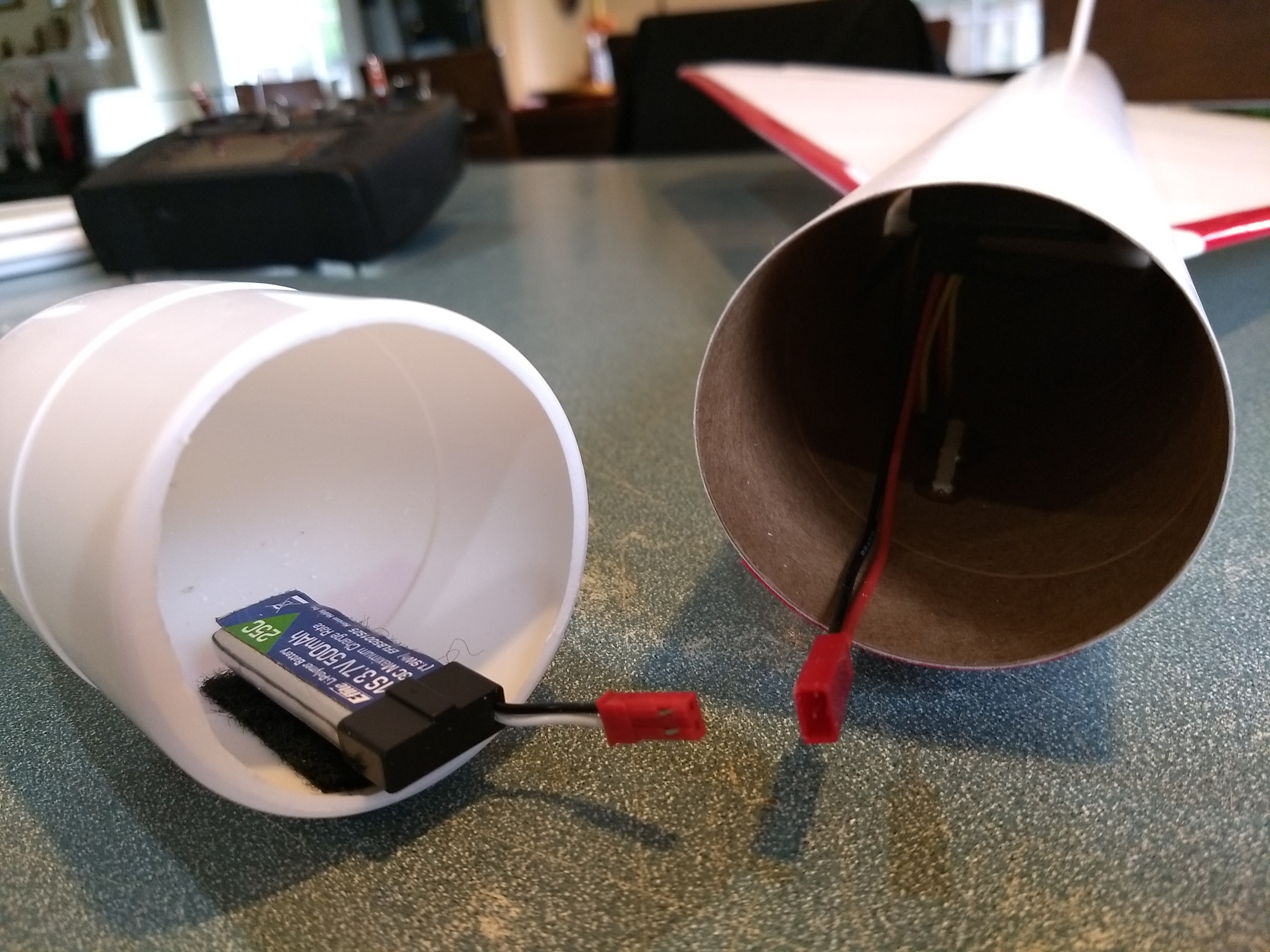
- Battery velcro’d to the inside of the nose
-
- Balancing model
-
- up elevator
-

- down elevator
-
- right aileron
-
- left aileron
-
- glide trim
-
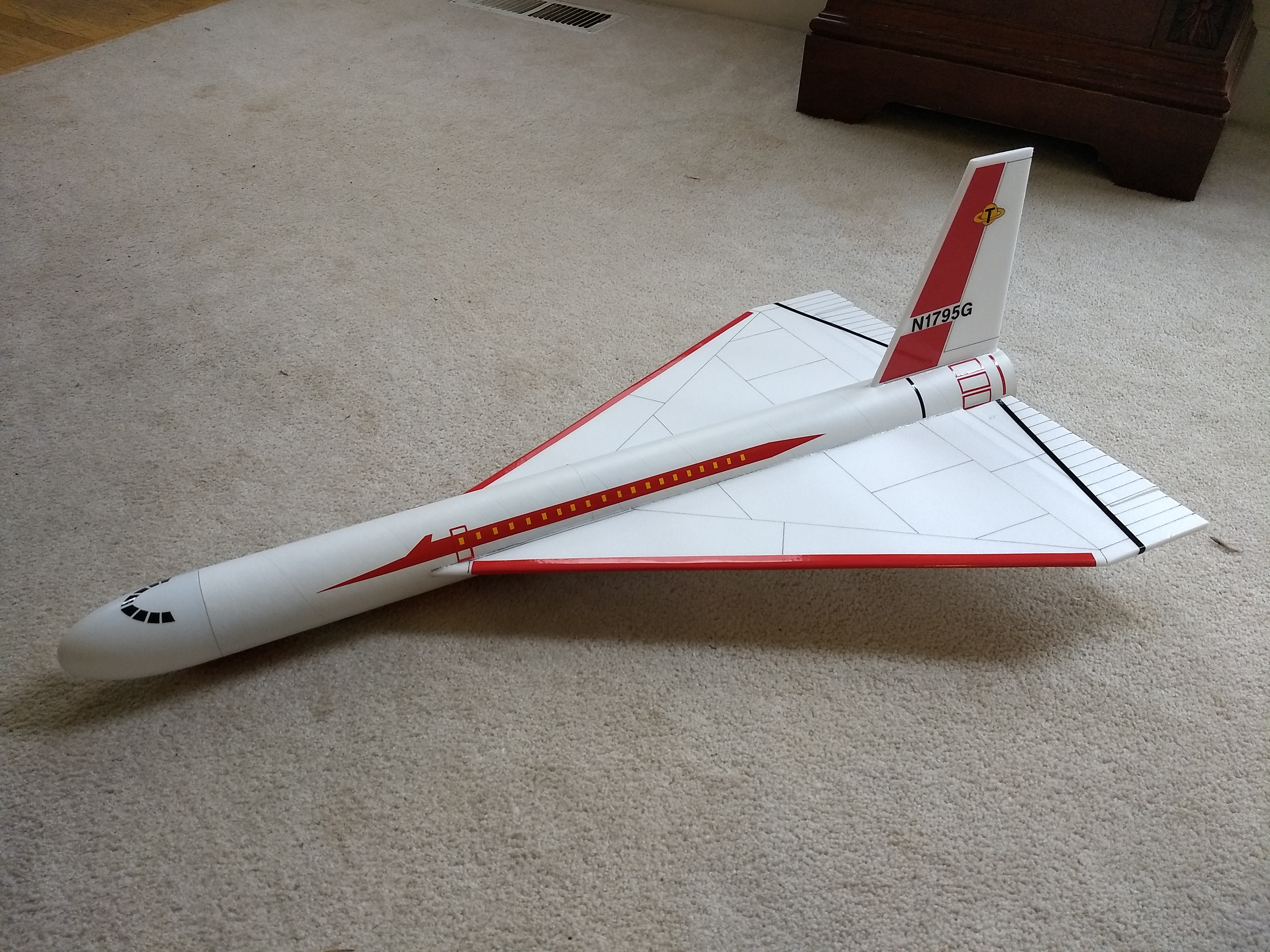
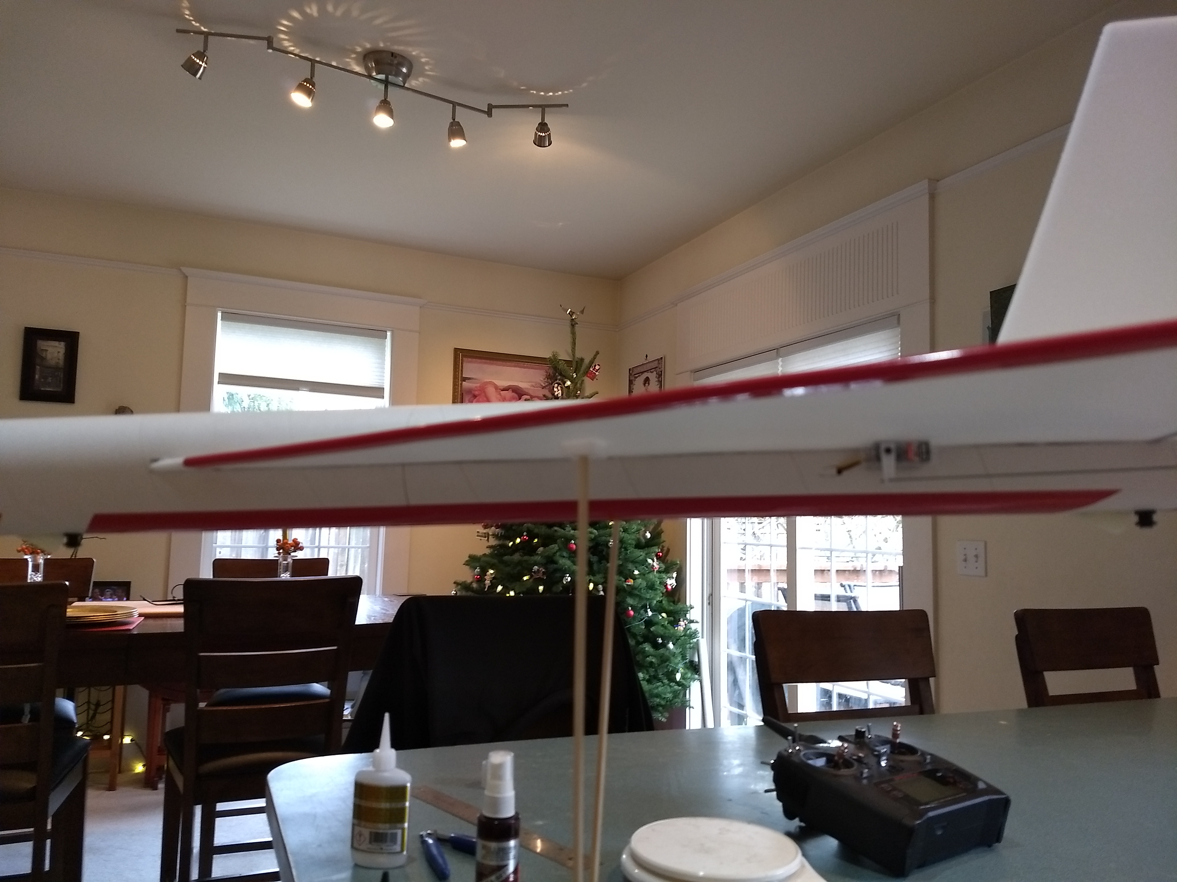
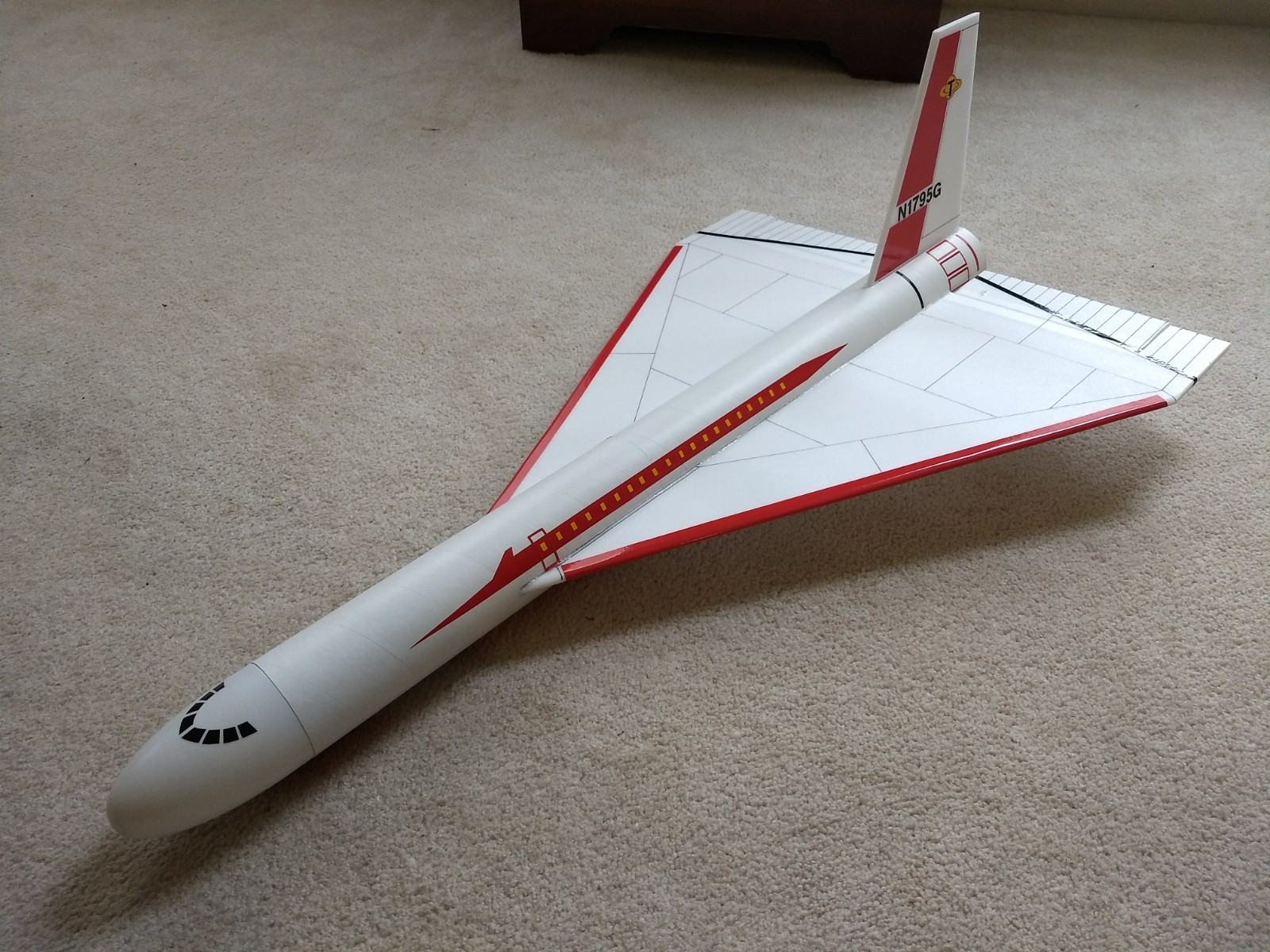
- Completed model
-

- Added red stripes to the wing tips
-
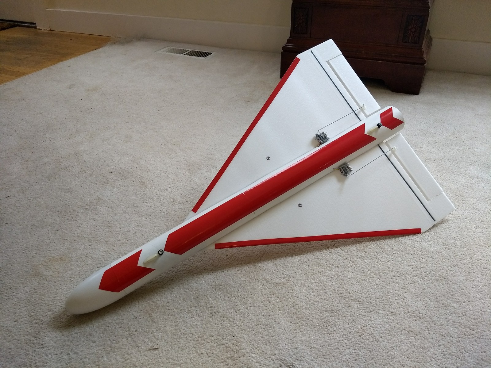
- Extra bottom stripe for orientation