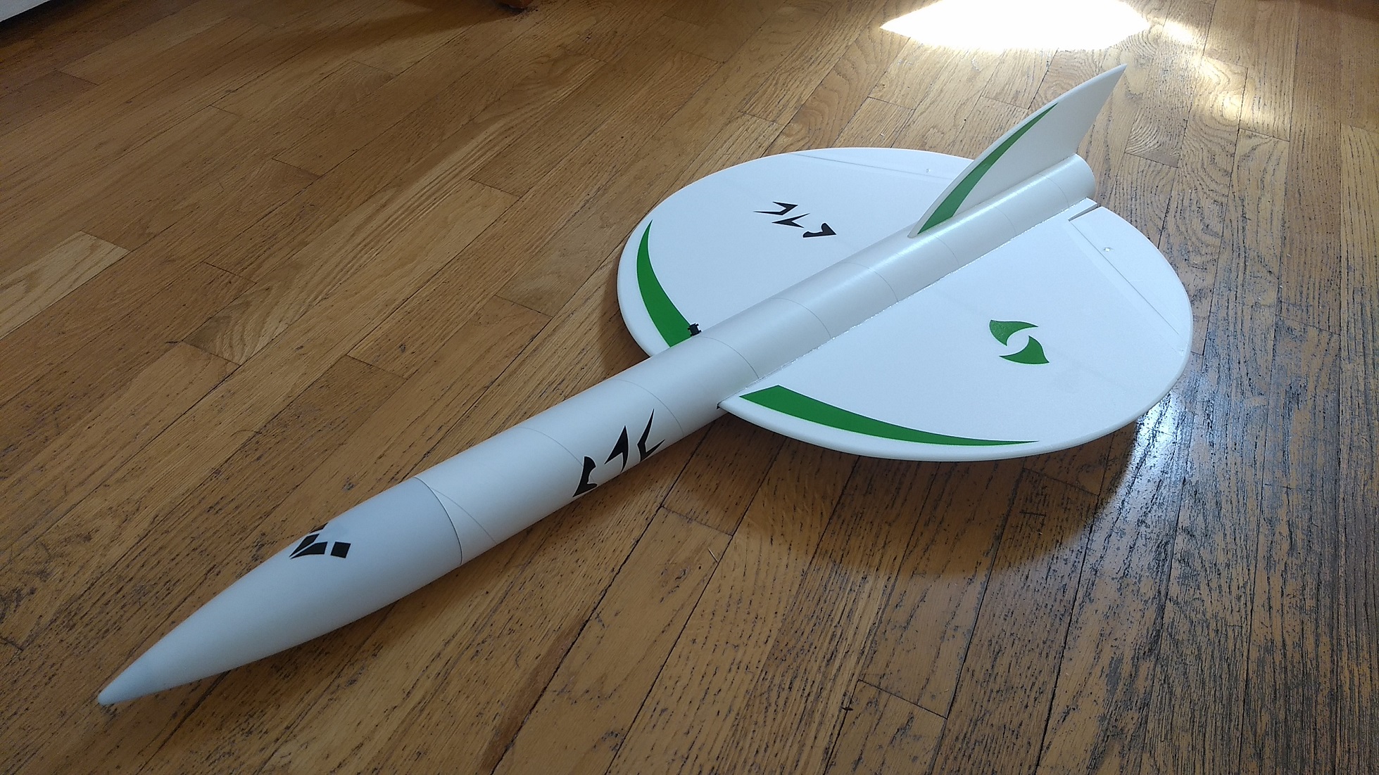
The Prometheus was discovered by a deep space salvage vessel, ancient and abandoned, its origin and purpose remain a mystery. A unique design with a disk shaped wing and a sleek graceful tail. The kit version comes with a plastic nose cone, 2.6″ white tubing for the body and 6mm Depron wing and tail. The wing spar is slot is pre-cut, control surfaces are pre-hinged, the body tube is pre slotted for the vertical stabs and wing and the rail button holes are pre-punched. For 24mm E6 motors and RC control. 36″ long, 2.6″ diameter, 19″ span, 10.85 oz ready to fly. Coming soon.. Please refer to the General information for all kits tab above, then read these instructions completely before starting assembly. High quality cut vinyl decals are available in your choice of colors from stickershock23 click HERE
(Note the picture of the kit on the stickershock website is for an older model, but these are the correct decals for this kit.)
CG location for rocket flight: 16 3/8″ forward of the rear end of the body tube.
Unpacking your kit:
The kits are packed to protect them in shipping, but the contents are fragile so unpack carefully. Carefully cut the tape holding the tubes in the box, then unwrap/lightly cut the plastic wrap to free the tubes, the spar may be packed in the tubes and the baggie with the little parts and nose cone will be in the tubes as well. Carefully cut the tape holding the cardboard wing protector in the box and carefully remove it, don’t pull hard or bend it. Then carefully cut the tape holding the cardboard top piece to the bottom. There may be some sticky tape holding the cardboard to the bottom cardboard piece, carefully peel it being sure not to bend anything. Once the top cardboard is free you can see the foam wing/tail parts, there are little fragile pieces in here, so unwrap carefully. It may be best to use an exacto to lightly cut the plastic wrap and carefully remove it without cutting into the foam. Make sure everything is free before you remove the pieces to avoid breaking anything. Kits contain one or two scrap pieces for repairs if you damage anything in construction or flight, just cut and patch in a spare piece of the foam if needed using foam safe CA+.
Welcome to the world of rocket boosted radio control gliders. This is not a model for a novice RC pilot, but anyone who is comfortable with RC flying of a medium speed model should be fine. Read through the instructions, look at the photos and be sure you understand the step before committing to cutting or glue.
Identify all pieces, the kit should contain:
1 wing
1 spar
1 Nose Cone
1 vertical stabilizer
2 control horns/Pushrods
2 Body Tubes
1 coupler
Motor mount
1 13/16″ x 2.5″ wide strip to center the motor tube
Velcro(for battery and rx/bec attachment)
2 Rail buttons with t nuts/screws
Blenderm Tape
Lead weight
Notes before starting:
Foam safe CA+(Bob smith super gold + is good) is the only glue recommended for construction. You will also need foam safe accellerator to set the glue.
You may use 320 grit sandpaper and a sanding block to slightly round the edges of the foam if you prefer before gluing the wing and vertical stab in place. Do any sanding before assembly.
Assembly:
- Unfold the wing and glue the taped joint with CA+.
- Glue in the spar and tape over the spar and center joint with included blenderm tape.
- Test fit the wing in the wing slot, sand or trim as needed so it does not drag on the wing and make grooves in the foam. Insert the wing. Make sure the wing is centered, look at the spacing of the elevons at the rear and look into the body tube at the front for the center joint and glue in place. You can insert the coupler in the rear a tiny amount to help the rear hold it’s round shape as you tack glue the rear of the wing, taking care not to glue the coupler in place. Then remove the coupler and insert it partially into the front of the tube and tack glue the front of the wing.
- Glue the vertical fin into place and make sure the vertical fin is straight up and down using a triangle or something similar. Apply a light filet to both sides of the vertical stab on the inside and outside of the body tube.
- Install the two rail buttons in the pre-punched holes in the slotted body tube.
- Glue the coupler into the front of the body tube with the wing installed it should stop against the rail button t-nut and go in about halfway.
- Glue the other tube onto the coupler so that the arrow marks on the bottom of both tubes are aligned, the tube is cut by hand and if you line up the marks the seam will be perfect.
- Glue the 2.5″ long foam strip on the motor tube using foam safe CA+ on any one of the three pencil lines. This helps center the motor tube in the body tube once you insert it into the body tube.
- Test fit the motor mount into the body tube/wing slot and under the fin tab. Make sure it fits, or sand the foam tab lightly. Glue the motor tube in place, it will inset about 3/4″ from the end of the body tube. Put a fillet on each side of the motor mount tabs and fuselage, Make sure the vertical stab stays vertical.
- Note that there should be two holes on each control surface. Apply CA+ to each of the control horns and press them in place in the underside of each control surface into the pre-made holes. The control horn holes face forward and the pushrod should be closest to the body tube. Apply a fillet around the control horn on the the prongs on the top of the control surfaces to lock them in place.
the basic construction of the airframe is complete.
Radio Installation
Note: Your radio needs to be configured for Delta mixing, this means that the servo arms will move the same direction during elevator stick movement and opposite for aileron stick movement. Connect your servos to the receiver one in the aileron connection and one on the elevator connection and apply power. Use a servo arm at least 9/16” long and with holes small enough that there won’t be slop with the pushrod wire when installed. I use the hole furthest out on the servo arm, to maximize movement. On some servos there are a long two-ended servo arm, you can trim off one end and use that arm to get sufficient length. Zero out any trim settings on the transmitter.
- Connect each servo to a pushrod. If the pushrod is too tight, you can use twist an X-Acto knife in the servo arm hole to make it larger, but be careful and do not make it too large. The servo should be next to the body tube on the bottom of the wing, with the servo electrical wire pointing forward and the servo arm pointing toward the wing tip. Hold each servo in place so that the control surfaces are centered. With the model right side up look at it from the rear. Moving the transmitter stick back(up elevator) should move both elevons up. Moving the transmitter stick to the right should move the right elevon up and the left elevon down. If you can’t get the servo reversing to give you the right polarity try swapping aileron/elevator inputs to the receiver or turning the servos over and swapping the servo arms to the other side of the output shaft. If that is correct, continue.
- Mark where the servo will sit next to the body tube with the control surface at neutral and the radio on, mark on the body tube and cut a pocket to fit the servo.
- Attach a 18″ or longer servo extension to each servo then route wire through the pocket to the front of the body tube and re-Attach the servo wires to the receiver and make sure they are going the right direction.
- Insert the servo in the pocket most of the way, make sure the control surfaces are neutral then apply glue around and underneath the servo making sure not to get any on the output shaft.
- Make sure the control surfaces are centered, use trims if needed to adjust. Now measure the control surface movement. Full elevator movement should be 1″ in each direction, aileron movement should be 1/2″ in either direction. All measurements at the inboard surface tip.
- If you have a flap/elevator mix you can program up elevator trim for boost and glide. You can also use a flight mode by setting the unique F mode elevator trim for each flight mode and use those for boost and glide settings. My model needed 1/2″ of uptrim for glide.
- Use the included Velcro to attach the receiver and battery as far inside the nose cone as I could to help reduce nose weight needed.
- I did not paint my model since it is all white, see the General instruction tab above on warnings for painting on foam. I did put a strip of clear packing tape on the bottom of the tube to protect it from dirt and moisture when landing on grass.
- If you use the stickershock decals, follow the picture for placement guidance. Once applied use a hot hair dryer to soften the decals and press down with a thumb or finger to set them into the foam surface.
- Install the receiver and battery
- Insert your heaviest loaded rocket motor into the motor mount
- Support the model upside down at the balance point indicated for boost. Glue as much lead weight included in the nose as needed to balance it. Do not try to fly the model too nose or tail heavy. Remember, a nose heavy model flies poorly, a tail heavy model flies once.
- Flying: See the General Instruction link at the top for flying instructions. Be ready on the first few flights to keep the model straight till you have the trims set perfectly for boost and glide.
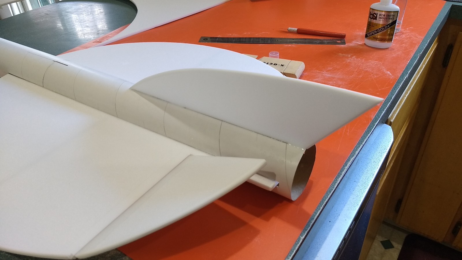
The photos below are for reference but please read through and follow the steps in order as the text is written as not all steps are shown.
-
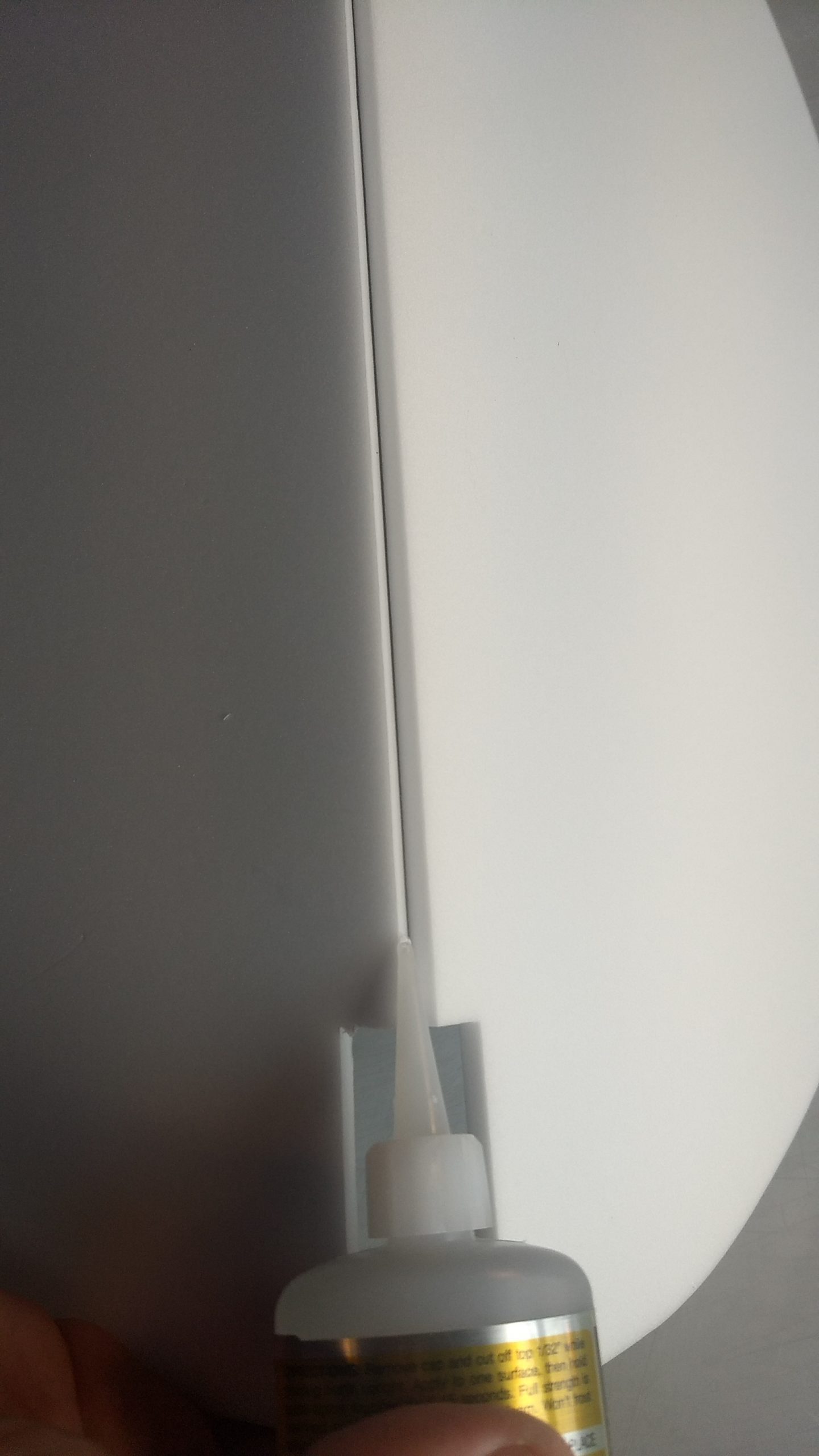
- Glue the taped wing joint and be sure it is cured,
-
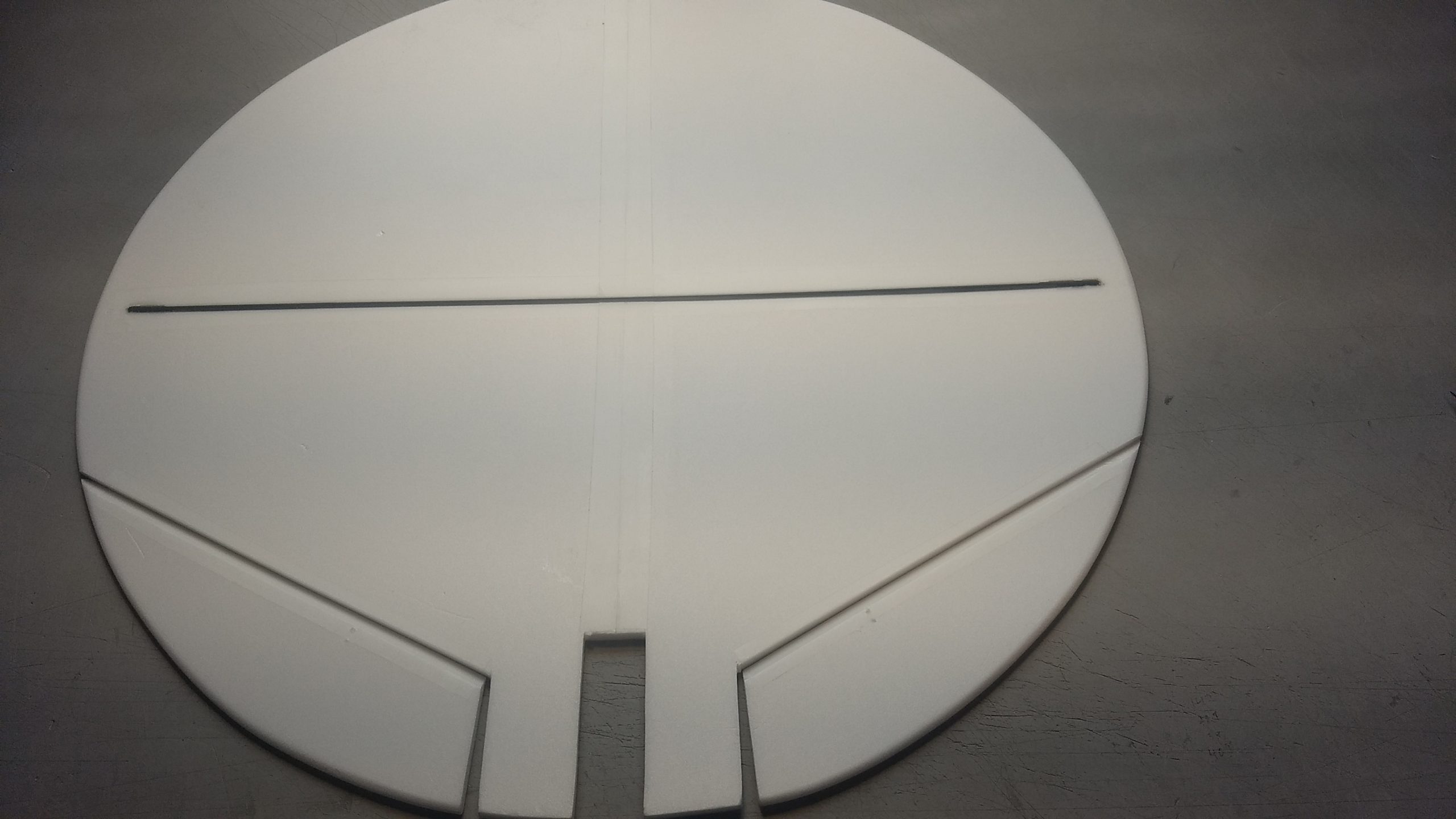
- Glue in the spar and tape over the spar and center joint.
-
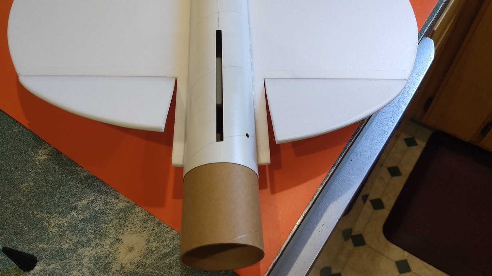
- Test fit wing in slot and glue when centered, use coupler at the front and rear to help hold the shape round as you tack glue the wing in place.
-
- glue in the vertical stab
-
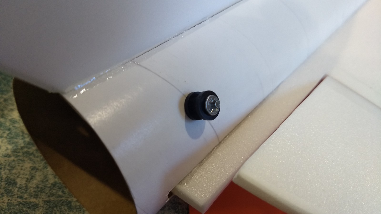
- Install front and rear rail buttons.
-

- Joint the two tubes with the coupler keeping the arrow marks on the bottom of the two tubes aligned. Once set finish cutting the wing slot in the rear tube/coupler on the lines marked.
-

- Glue the motor tab on any one of the alignment lines on the motor tube.
-

- test fit the motor mount, trim tab as needed so it makes a snug fit
-
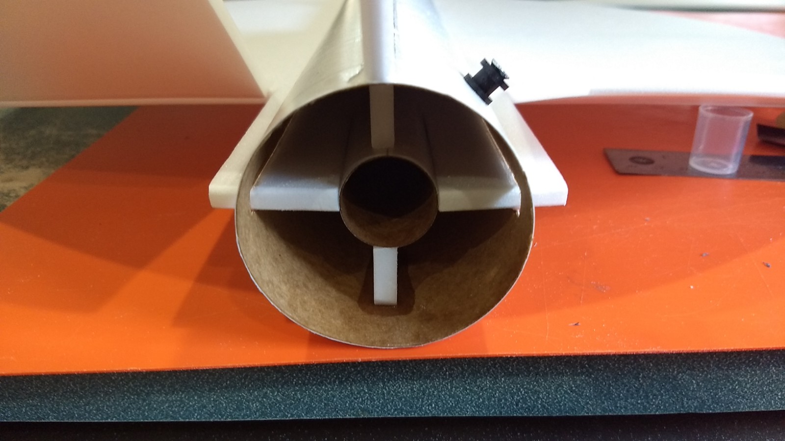
- Inset the motor tube till it stops, then fillet the joints.
-
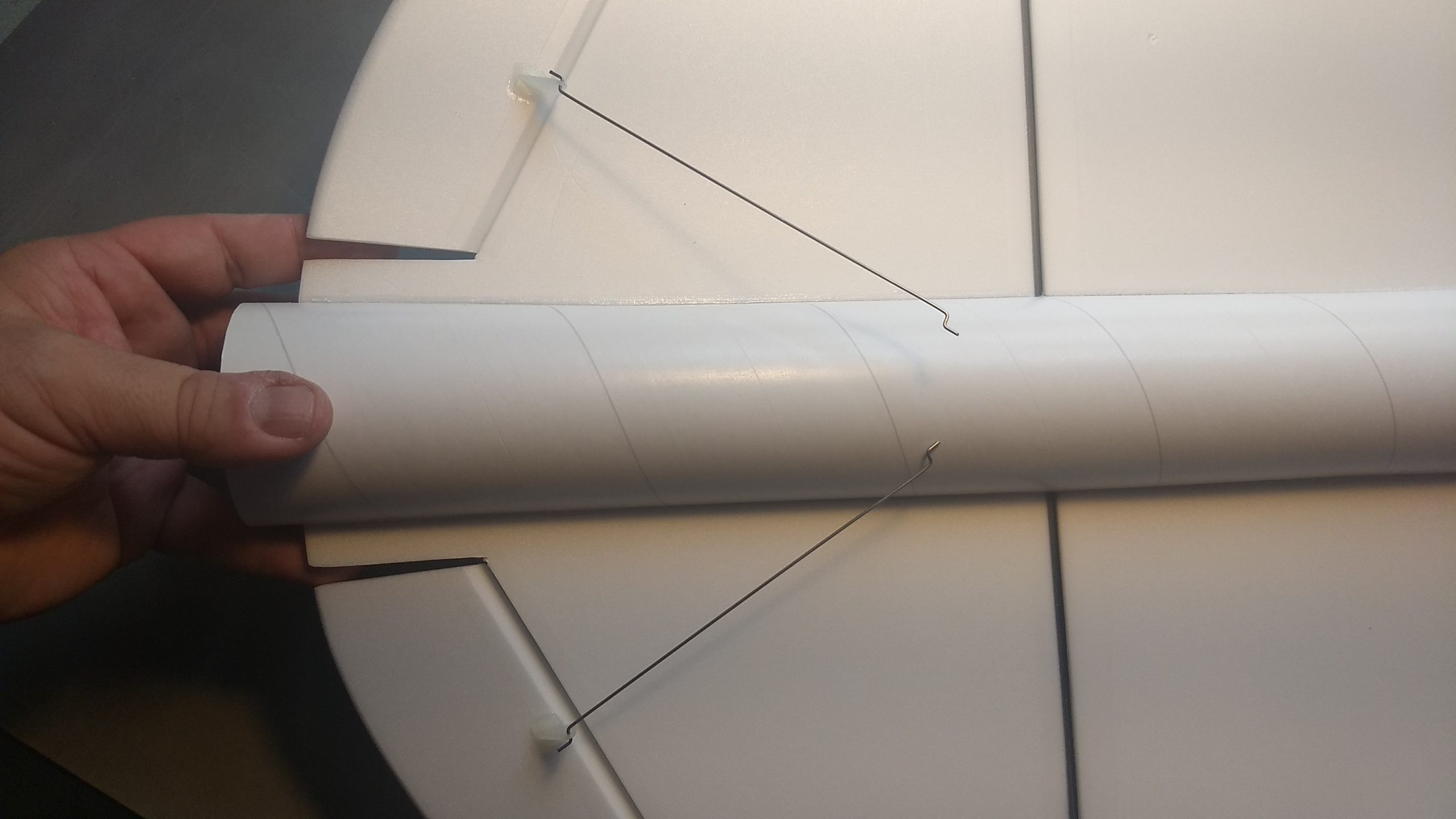
- Glue in the two pushrods in the pre made holes in the bottom of each control surface.
-

- Apply glue to the tops of the horn prongs to lock them in place.
-
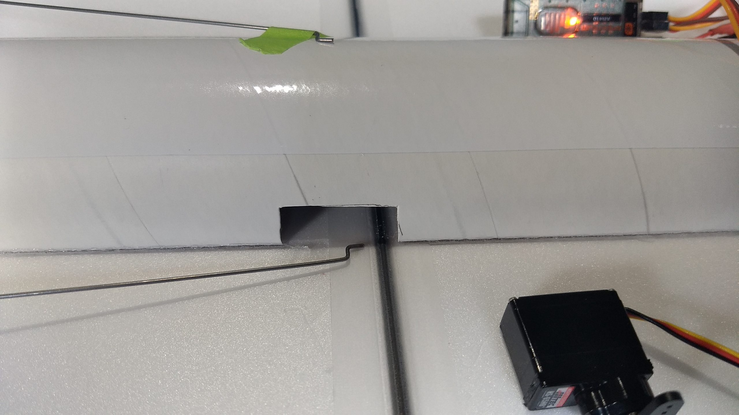
- Cut servo pocket
-
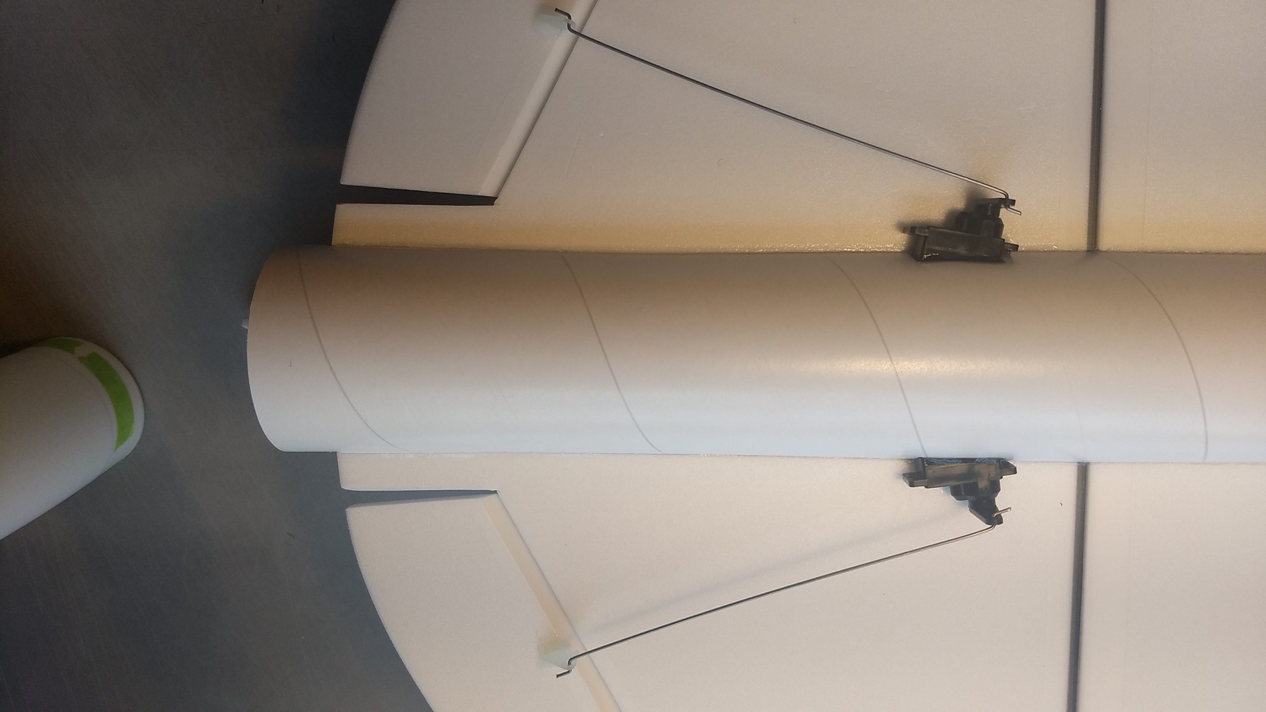
- Servos glued in place and servo wires routed to the front of the model using servo extensions.
-
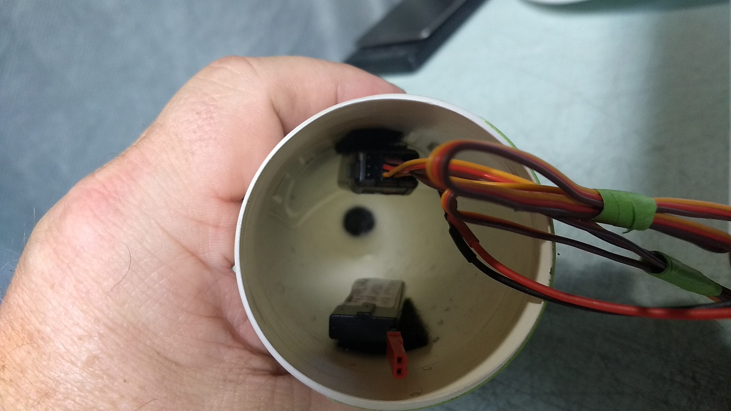
- attach the receiver and battery inside the nose cone with included velcro.
-
- Completed Model
-
- Example of stickershock Decals