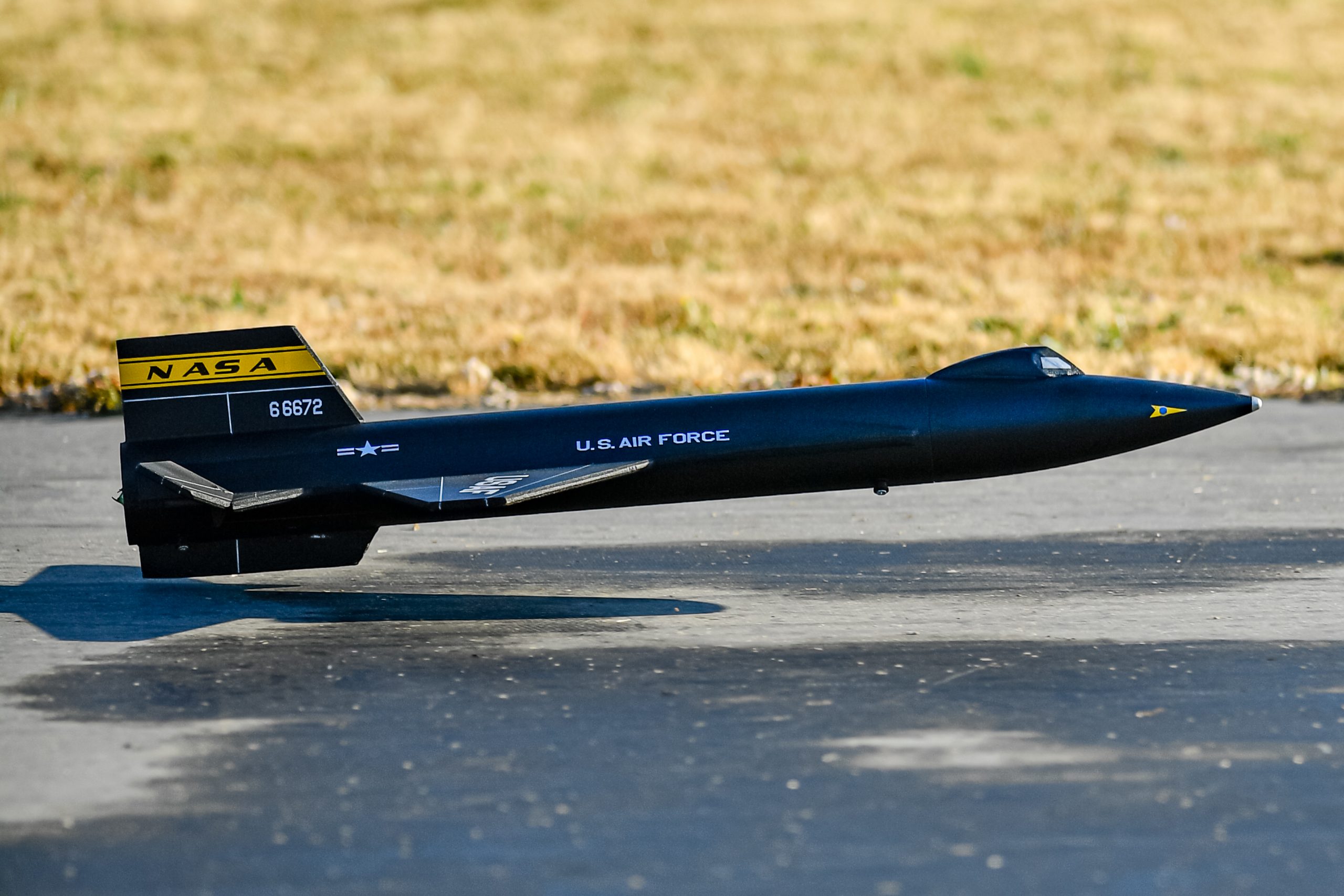
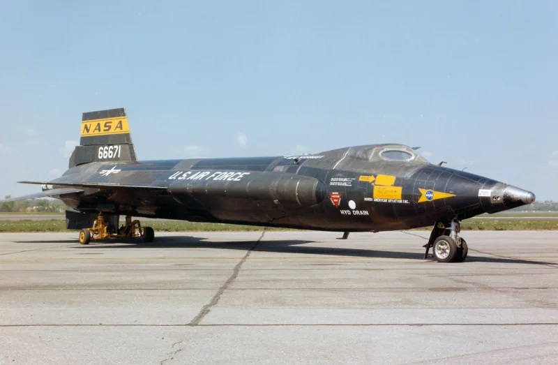
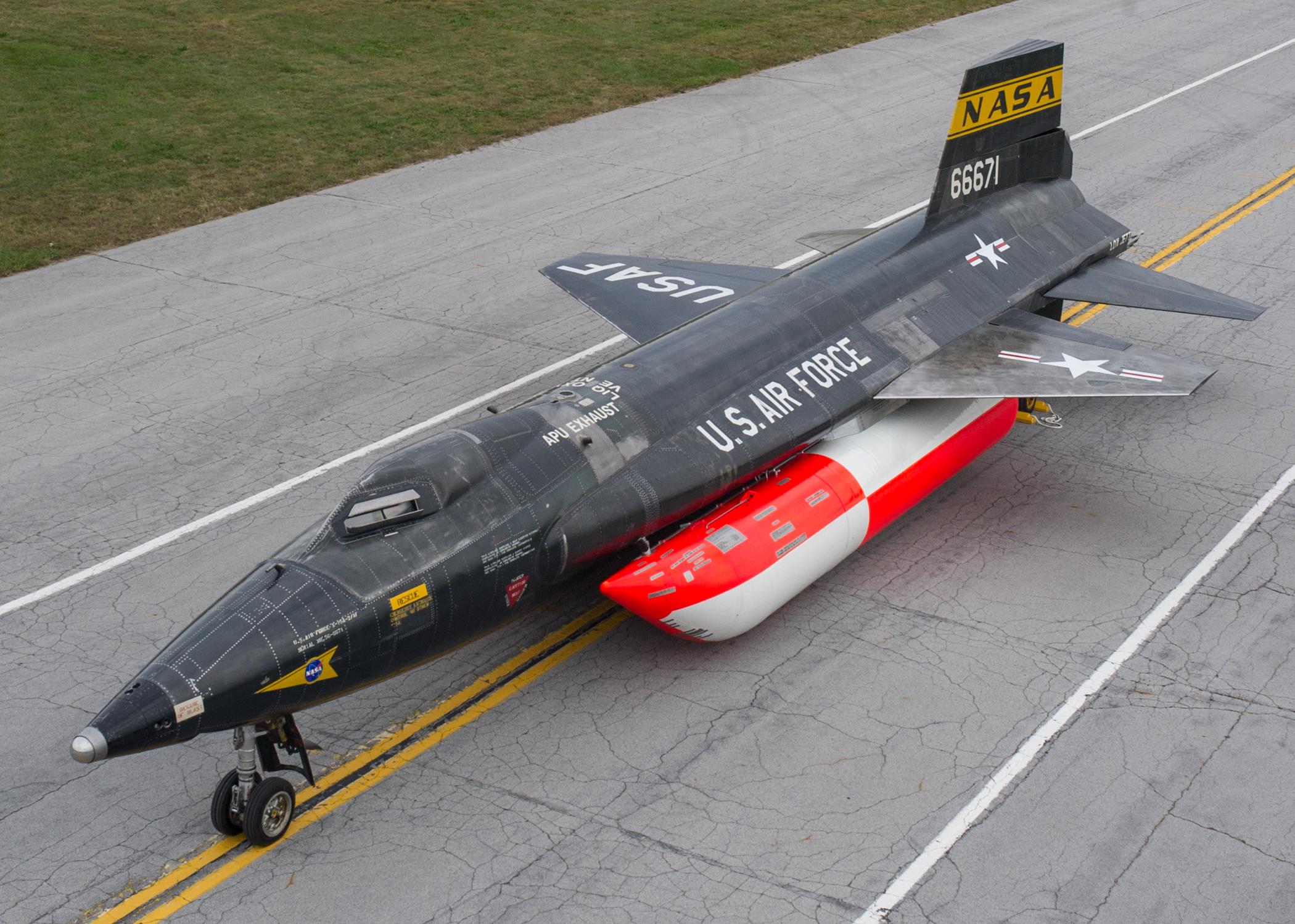
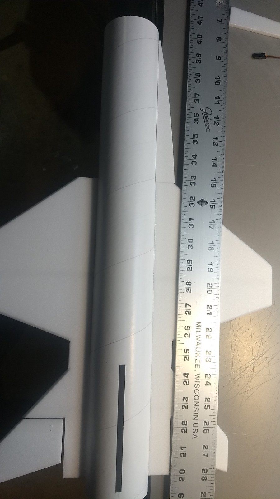
The X-15 RC Rocket glider kit is modeled after the hypersonic reasearch vehicle that flew with the XLR-99 engine and without the extended lower ventral. The kit includes pre-slotted body tube, plastic nose cone, pre-hinged control surfaces, pre-installed spars and pre-cut 6mm depron tail surfaces and wing. Length 28.25″, wingspan 14″, weight for the 24mm version is approximately 8.8 oz rtf. It is 1/21 scale however I made a few concessions to make assembly easier and to keep wing loading as low as possible. ***Note that this kit is below the 250 gram(8.8oz) ready to fly limit and does not require FAA drone pilot registration and markings and will not require remote ID when that comes into effect in September 2023.
The current 24mm Kit is designed for Composite E-6 Aerotech rocket motors.
The previous 18mm kit was designed for Composite D-24 and D-13 18mm Aerotech reloadable motors using the plugged forward closure, you can also use those motors in the current kit with a 24 to 18mm adapter(not included) Just two 24mm centering rings and an 18mm motor tube. The plugged closure or using JB weld to plug the ejection hole of the forward closure is recommended to prevent any gas leakage or blow through from the delay element from damaging the internal foam wing. You can use any of the 4, 7 or 10 second delay elements because you aren’t using an ejection charge. These will give you boost altitudes of around 400′ I balanced my model for the E-6 which put the battery in the nose cone, for using the 18mm Motors I put an extra piece of velcro inside the bottom front of the body tube about as far back as I could reach with the battery, about 2-3″ back, doing this I did not need to adjust any glide or boost trims and it worked great with the adapter.
High quality cut vinyl decals are available HERE select the white lettering for a black painted model, X-15 small size, NOT THE DELTA set.
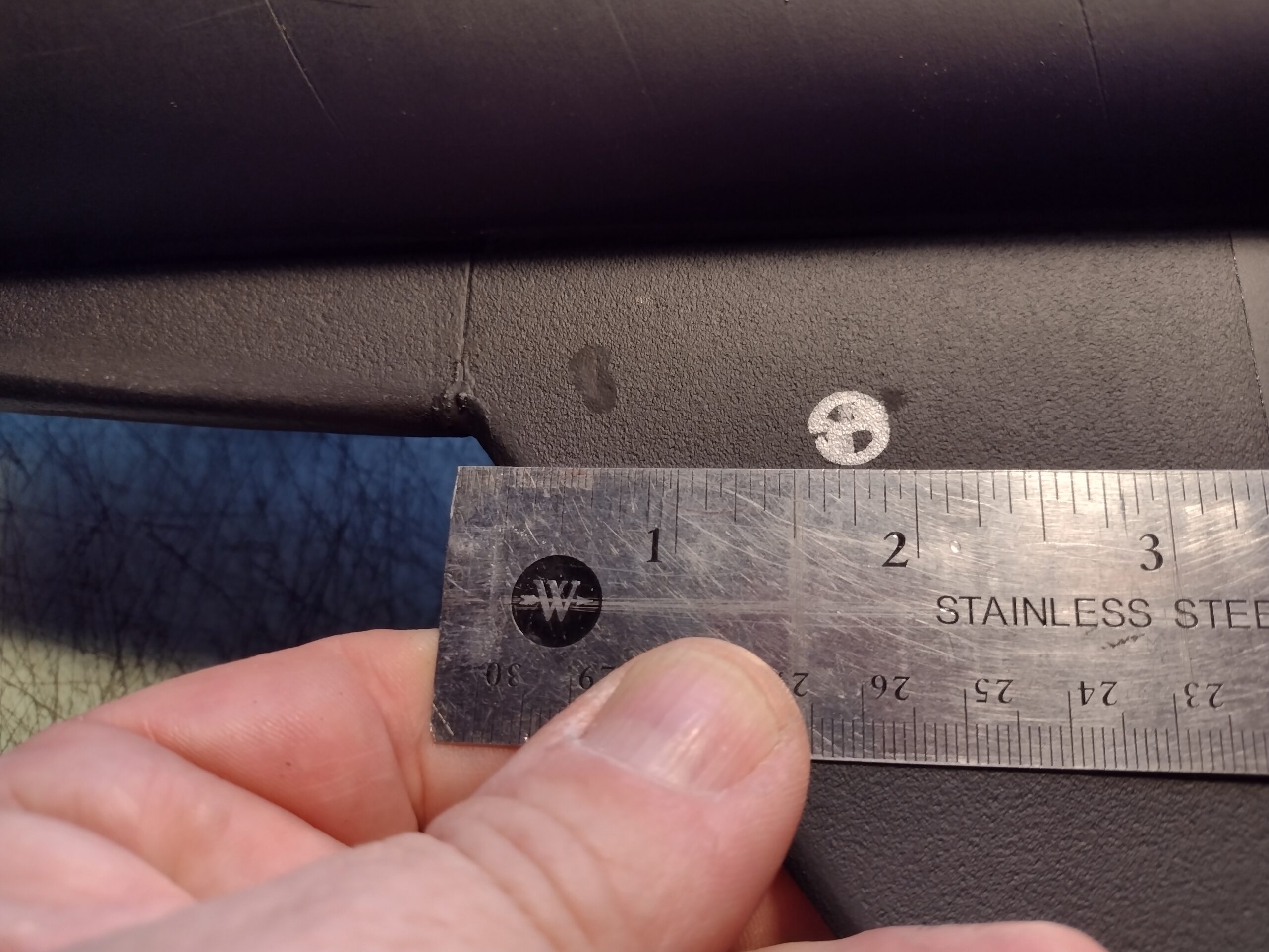
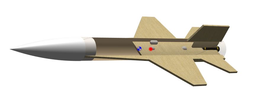
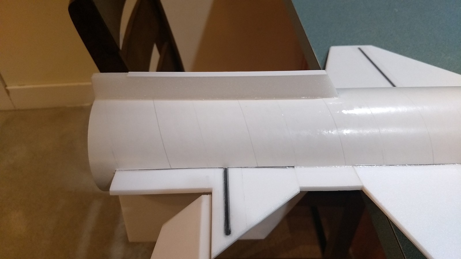
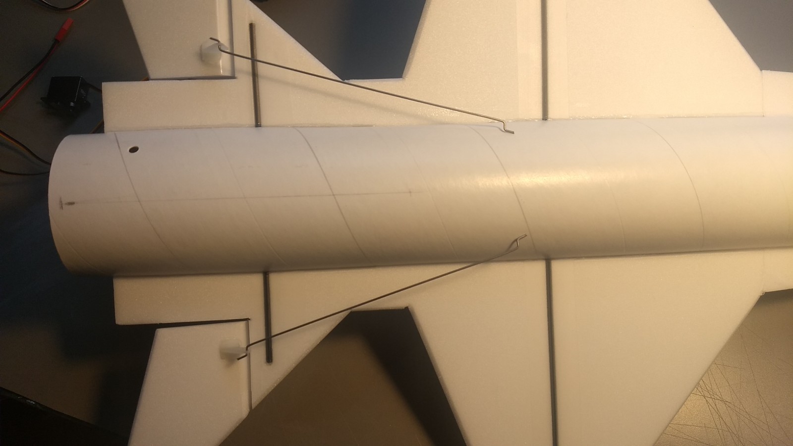
CG location for rocket flight with battery and motor installed: Looking at the bottom of the model the front to the left, the CG is 1.75″ to the rear of the joint where the chine glues to the leading edge of the wing as shown below.
Loading the Aerotech D-13 18mm motor if you choose to use them with an adapter(not provided in kit)
This model is small and boosts fast. You need to be a competent pilot to fly this model, it isn’t hard but it isn’t tolerant of boost and stall mistakes. Weight is CRITICAL on this model, be sparing with glue and paint and it will fly very nicely. I used hitec hs-35055 digital metal gear servos which have good repeatable centering and are only 9.3 grams, I wouldn’t use a heavier servo than this.
Please refer to the General information for all kits tab above for information on painting, launch pad and radio equipment, then read these instructions completely before starting assembly.
Unpacking your kit:
The kits are packed to protect them in shipping, it comes in two boxes, The contents are fragile so unpack carefully. Carefully cut the tape holding the tubes and cone in place and unwrap/cut the protective wrapping. The body tube is wrapped with paper to help hold the shape of the tube, only remove this paper once you are ready to install the wing and tail since the tube tends to flatten out after cutting the slots. In the other box, carefully cut the tape holding the cardboard wing protector in the box and carefully remove it, don’t pull hard or bend it. Then carefully cut the tape holding the cardboard top piece to the bottom. There may be some sticky tape holding the cardboard wing protector to the bottom cardboard piece, carefully peel it being sure not to bend anything. Once the top cardboard is free you can see the foam wing/tail parts, there are little fragile pieces in here, so unwrap carefully. It may be best to use an exacto to lightly cut the plastic wrap and carefully remove it without cutting into the foam. Make sure everything is free before you remove the pieces to avoid breaking anything. Kits contain one or two scrap pieces for repairs if you damage anything in construction or flight, just cut and patch in a spare piece of the foam if needed using foam safe CA+.
Welcome to the world of rocket boosted radio control gliders. This is not a model for a novice RC pilot. Read through the instructions, look at the photos and be sure you understand the step before comitting to cutting or glue.
Identify all pieces, the kit should contain:
Wing and stabilizer unit 6mm
Vertical stabilizer 6mm
2 long .75″ wide chines 6mm
2 1.25″ wide 3mm chine covers
4 cockpit profiles(6mm)
1 lower ventral fin(6mm)
1 slotted body tube
2 rail buttons and blind nuts/screws
2 pushrods
Nose cone
Motor mount tube
Velcro(for battery and rx/bec attachment)
1 6mm wide styrene strip for reinforcing the ventral fin
Lead weight
1 foam mmt mounting strip
Spare depron
Notes before starting:
Foam safe CA+(Bob smith super gold + is good) is the only glue recommended for construction except for some epoxy just to hold the nose weight in place. You will also need foam safe accellerator.
Fuselage Assembly
- If you want to bevel the leading and trailing edges of the wing and horizontal stab now, do so before assembly. Use a straight edge and sharp exacto to do a small 1/16″ or so 45 degree bevel cut on both sides. Bevel the leading edge of the vertical stabilizer, the leading and trailing edges of the wing and horizontal stabilizers only, the rest of the edges should stay flat for now till assembly is completed.
- Unfold the wing/stabilizer and glue the taped joint, lay flat till it is set.
- Insert the wing/stabilizer into the slot in the fuselage. The vertical tail slot in the tube will be UP and the spar will be facing down. Apply a fillet of glue on the wing/tube joint on the top and bottom, make sure this is set, you don’t need to be heavy handed it just needs to keep the wing from moving and the upper chine cover will also glue to the wing and body.
- Install the front and rear rail buttons in the pre-made holes.
- Glue the vertical stab into the rear slot keeping it perpendicular to the wing and fillet the outside joint.
- Glue the small foam motor mount centering strip onto the motor tube keeping it relatively straight. Test fit the motor mount into the rear of the model. The motor tube is supported left and right by the horizontal tail slot and on top by the vertical stab tab. The tab on the mount is pointing down. You may need to sand the tab slightly till the mount will just insert snugly, make sure the vertical stab stays vertical then glue in place. The motor mount should stop against the front of the horizontal stab slot. Make sure the motor tube is attached well but don’t overdo it and don’t use epoxy, tail weight is a killer and there isn’t much force on the motor tube during launch. The foam is plenty strong enough to support the forward thrust and no thrust ring is needed.
- Glue the styrene strip onto the lower ventral, this helps provide some landing protection, then glue the lower ventral fin on the rear bottom of the fuselage on the line marked.
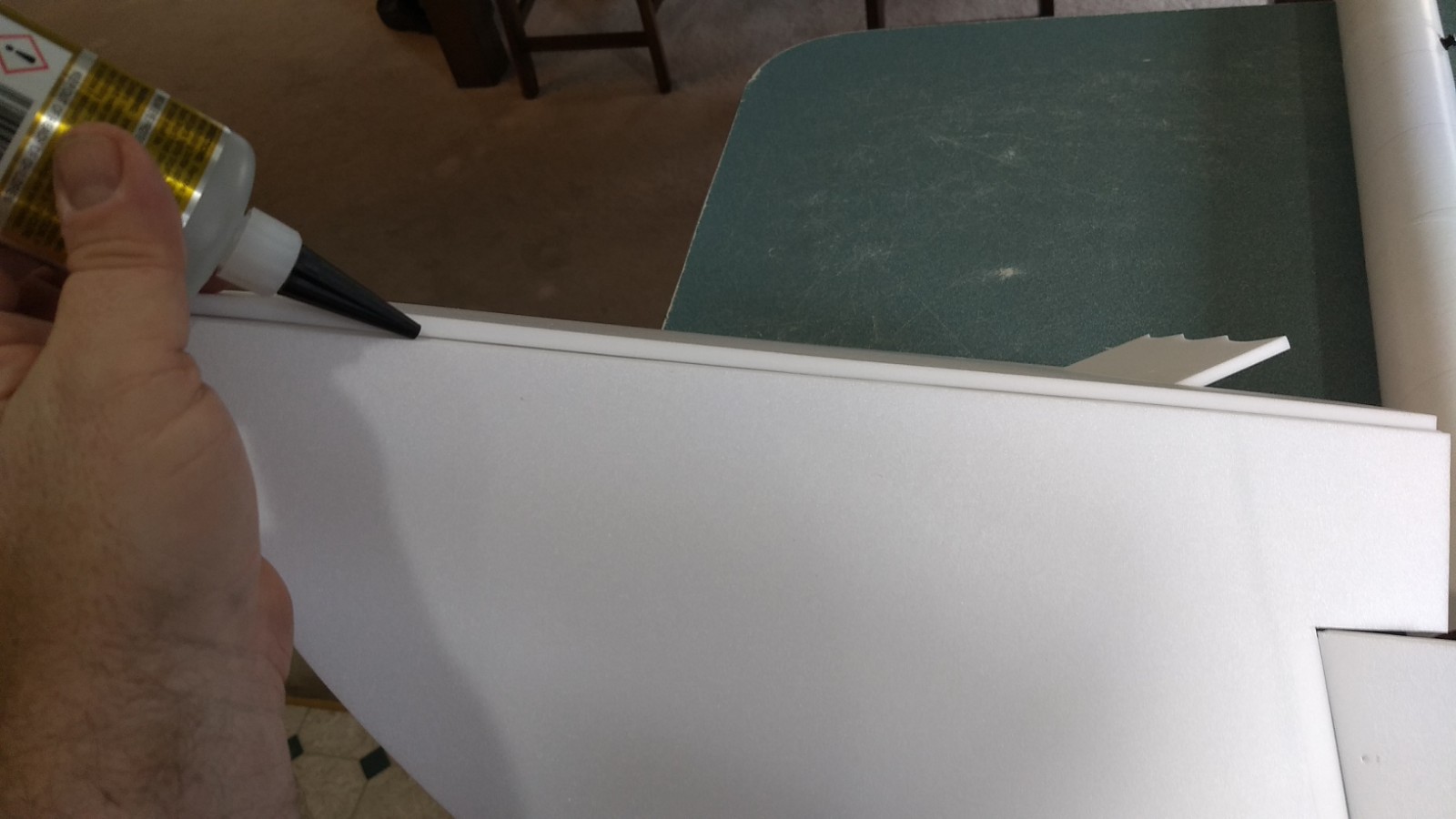
- Set the model with the wing along a table edge and put something like a book to hold the wing and model in place on the table with the body tube about 1/4″ away from the edge. Put a bit of wax paper under the front of the wing and glue the chine to the body and against the front of the wing. The edge of the table will help make sure the wing and chine are aligned straight. Repeat on the other side and then lightly fillet the top and bottom of the chine.
- Sand a 3/16″ wide bevel on both edges of each chine cover on the side that is marked “glue” There is a left and a right. Take your time and go slow so you don’t damage or tear the chine cover.
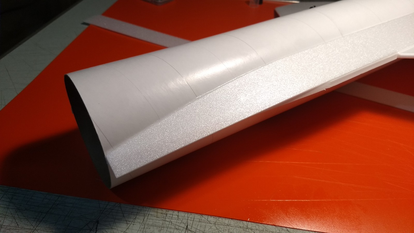
- Test fit, then glue the two chine cover plates to the wing, chine and fuselage. Start at the rear of the model with the cover plate even with the end of the horizontal stabilizer extension, glue it just to the foam stabilizer not the body tube yet, continue forward gluing to the wing. Continue gluing to the chine, at the front you may need to bend the cover down to touch the chine till the glue sets. The front portion will overlap the chine to allow trimming later. Note the curved portion will go against the body tube at the front and have to be pulled down till it just is even at the front with the tip of the chine. Once set, wick some CA under the chine cover and body tube along the entire length and wipe off any excess. Make sure it makes good contact with the body tube and is set. Trim the chine cover at the front to match the chine profile and sand the front edges round. There are no chine covers on the bottom of the model to save weight and avoid having to trim around the servo mounting, in flight and normal viewing you won’t even notice.
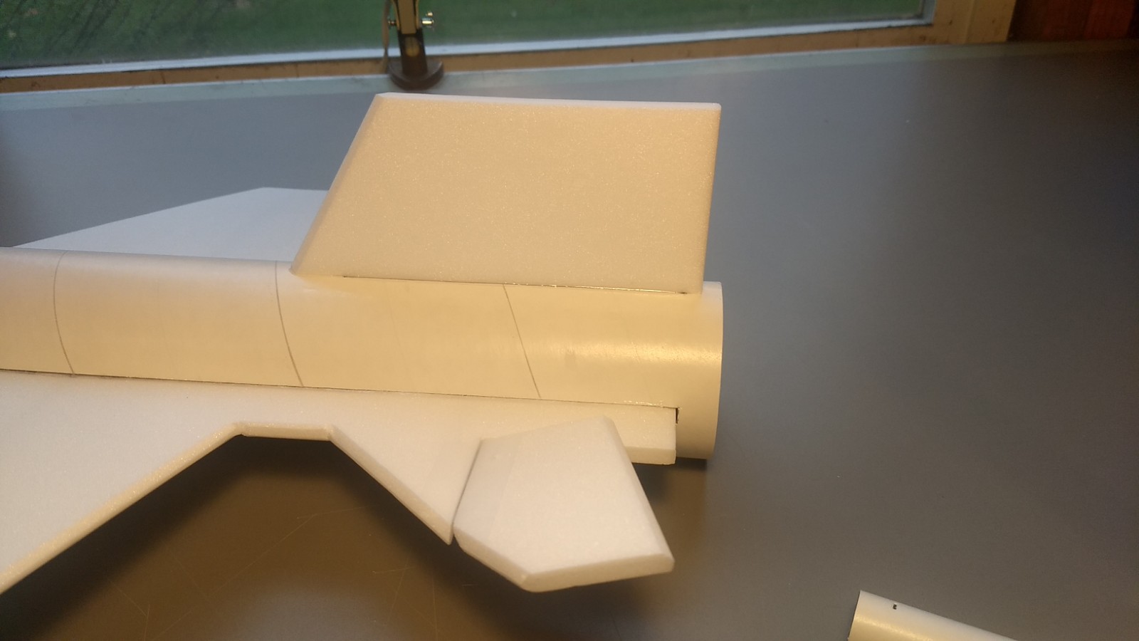
- Glue the four cockpit pieces together. Use the provided templates to cut the top view to shape, then bevel the front of the cockpit on both sides and round the rear portion as per the photos.
- Glue the pushrods/control horns into the holes premade into the bottom of each control surface, note the pushrod should be closest to the fuselage and angle inward, there is a left and right. See picture for clarity.
- Wrap some 320 grit sand paper over the nose cone and gently sand the bottom of the cockpit till it conforms to the rear of the nose cone.
- The cockpit is glued so the rear of the cockpit is even with the beginning of the nose cone shoulder. Tack glue the cockpit to the cone using foam safe CA+ Apply a fillet to the cockpit on both sides. I also carefully applied a few coats of foam safe CA+ to the cockpit to harden it and make it take paint/filler better. Add a little at a time to avoid heat/melting.
- If the nose cone shoulder is a slightly loose fit, simply use masking tape to make a friction fit.
The basic construction is now complete.
Radio Installation
Note: Your radio needs to be configured for Delta mixing, this means that the servo arms will move the same direction during elevator stick movement and opposite for aileron stick movement. Connect your servos to the receiver one in the aileron connection and one on the elevator connection and apply power. Use a servo arm at least 9/16” long and with holes small enough that there won’t be slop with the pushrod wire when installed. I use the hole furthest out on the servo arm, to maximize movement. On some servos there are a long two-ended servo arm, you can trim off one end if needed to get sufficient length. Zero out any trim settings on the transmitter. The model once the motor has burned out is nose heavy and loses pitch authority in glide so you want as much up elevator travel for trim/flare as possible.
- Install the free end of the pushrod to the servo output arm, again making sure the servo electrical wire is toward the fuselage side of the model and pointed toward the rear. If the wire is too tight, you can twist an exacto knife in the servo arm hole to make it larger, but be careful and do not make it too large. The servos will butt against the body tube and glue to the bottom of the horizontal wing and chine filler between the wing and horizontal tail. Repeat for the other side. If your servo wires are long enough you can route them out the back of the model and connect them to the receiver. If not you will need to attach a short lightweight servo extension to get the wires out the rear of the model to attach to the receiver. Connect the battery and power up the radio.
- Once connected, tape each servo in place so that the control surfaces are centered. Flip the model right side up and look at it from the rear. Moving the transmitter stick back(up elevator) should move both stabilizors TE’s up. Moving the transmitter stick to the right should move the right TE of the stabilizer up and the left one down. If you can’t get the servo reversing to give you the right polarity try swapping aileron/elevator inputs to the receiver or turning the servos over and swapping the servo arms to the other side of the output shaft. If that is correct, continue.
- Flip the model upside down and supported. The servos may be attached to the model using double back servo mounting tape(not included) or by directly gluing the servo to the wing with CA+ or a small amount of epoxy. Double back servo tape can loosen over time and with exposure to heat, I prefer to glue the servo in place.
- Mark the fuselage where the servo will go and cut a pocket out of the body tube and cut it out and test fit, you need the servo to fit with the control arm neutral and have the horizontal stabilizers be level with the wing and stabilizer. Route the servo wire out the back of the model, make sure you route the left and right servo wires on the SAME side of the internal motor mount so that you can connect to the receiver and slide the whole thing forward. Connect the servos to the receiver and connect the battery and power up the radio.
- With the radio still on, put a small amount of glue on the servo, being careful not to get any near the output shaft. And set it in place on the model in the pocket keeping the control surface centered. Do the same to the other side. Make sure the glue is set before continuing. Apply a small amount of velcro to the bottom of the rx and push it forward to the front of the model with the battery still connected.
- Flip the model back right side up. Make sure the control surfaces are centered, use trims if needed. Now measure the control surface movement. Full elevator and aileron movement should be 5/8” in each direction measured at the inboard end of the control surface. Since the model will be nose heavy, extra stabilizer movement helps to give sufficient authority during glide. Roll rate is not extremely fast during glide so you need plenty of movement. Set up dual rates with lower movements if you are worried but boost with higher settings till you are comfortable.
- If you have a flap/elevator mix you can program up elevator to a switch setting. The model needs approximately 3/8”-1/2″ of up elevator measured from the inboard end of the control surface, during glide. Boost will use completely neutral settings for the first flight. If you can’t set the up elevator to a switch on your radio you’ll have to manually put in glide trim which is hard to do while flying the model.
- To paint the model you can remove the rail buttons and t-nuts or tape over them before painting. I recommend ONLY Model Master or testors flat black enamel spray paint or Krylon Short cuts small rattle can spray enamel for painting directly on the foam. I spray the edges first since those tend to soak more paint and need re-coating, then do the flat areas. It took about half a can to do my prototype.
- Use a silver sharpie to add panel lines or wing flap and elevon details if desired.
- If you use stickershock markings, it helps once applied to use a hot hair dryer to soften the decal then push down with a finger to really set them into the model. Be careful when applying over painted foam as when removing the backing tape you need to roll the backing off carefully while pushing down firmly. If you pull straight up you will pull the paint off the wings and the decal won’t stick any more. The x-15 had many little variations in markings. The yellow arrow and blue ball was sometimes on the nose, the nasa logo was typically burned off during flight so that is left off of the decal. Sometimes the aircraft had X-15 text on the nose. The decals from stickershock include both. It also contains round and angled cockpit windows, on the high speed flights the left window was covered by a rectangular door which was opened for landing and the right window was rounded. Or you can use both angled or both round windows, I’ve seen both depending on what time in the program it was. There are two sizes of window decals, use the ones that look the best to you.
- Re-install the rail buttons, battery and insert a loaded rocket motor into the motor mount. Use the heaviest motor you plan on flying.
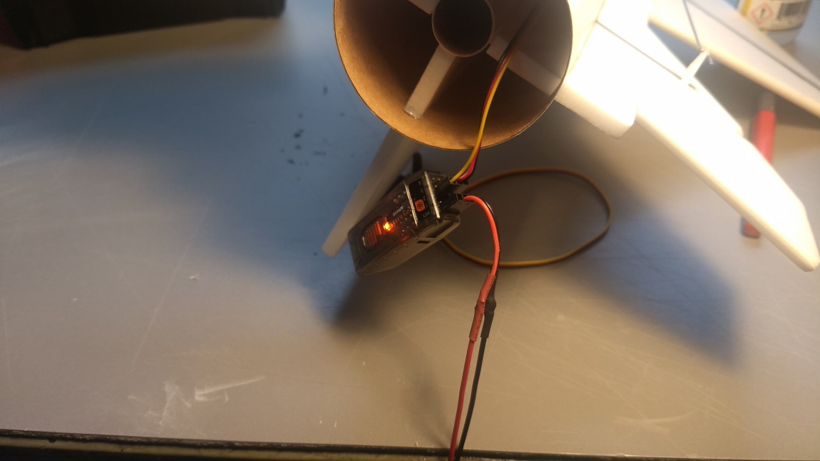
- Temporarily tape the receiver and battery just inside the nose cone to test the balance.
- Support the model at the balance point indicated for boost. I use two pencils with rounded erasers cut to a bevel which will allow a precise balance point and not damage the foam. These are held in place with small bench vices or use a balancing tool. On such a small model using your fingers is not precise enough. Place the model right side up on the pencil erasers on the location indicated above so that the model balances slightly nose down. You can move the receiver and battery forward or backward as needed and then use the included velcro to mount them in place. Mine are inside the front of the body tube as far back as I can comfortably reach them. If needed, add small amounts of included lead to the nose or tail as needed to achieve a slightly nose down balance.
- Do not fly the model with it balancing it behind this point. The adage is, a nose heavy model flies poorly, a tail heavy model flies once.
- The 18mm model was designed and tested to use the Aerotech composite D-13 and D-24 motors with plugged forward closure, the 24mm version uses the Aerotech single use or reloadable E-6 motor ONLY!. Simply use a small amount of tape over the rear of the motor and igniter and tape to both sides of the motor tube to keep the igniter from falling out and the motor from falling out after burnout.
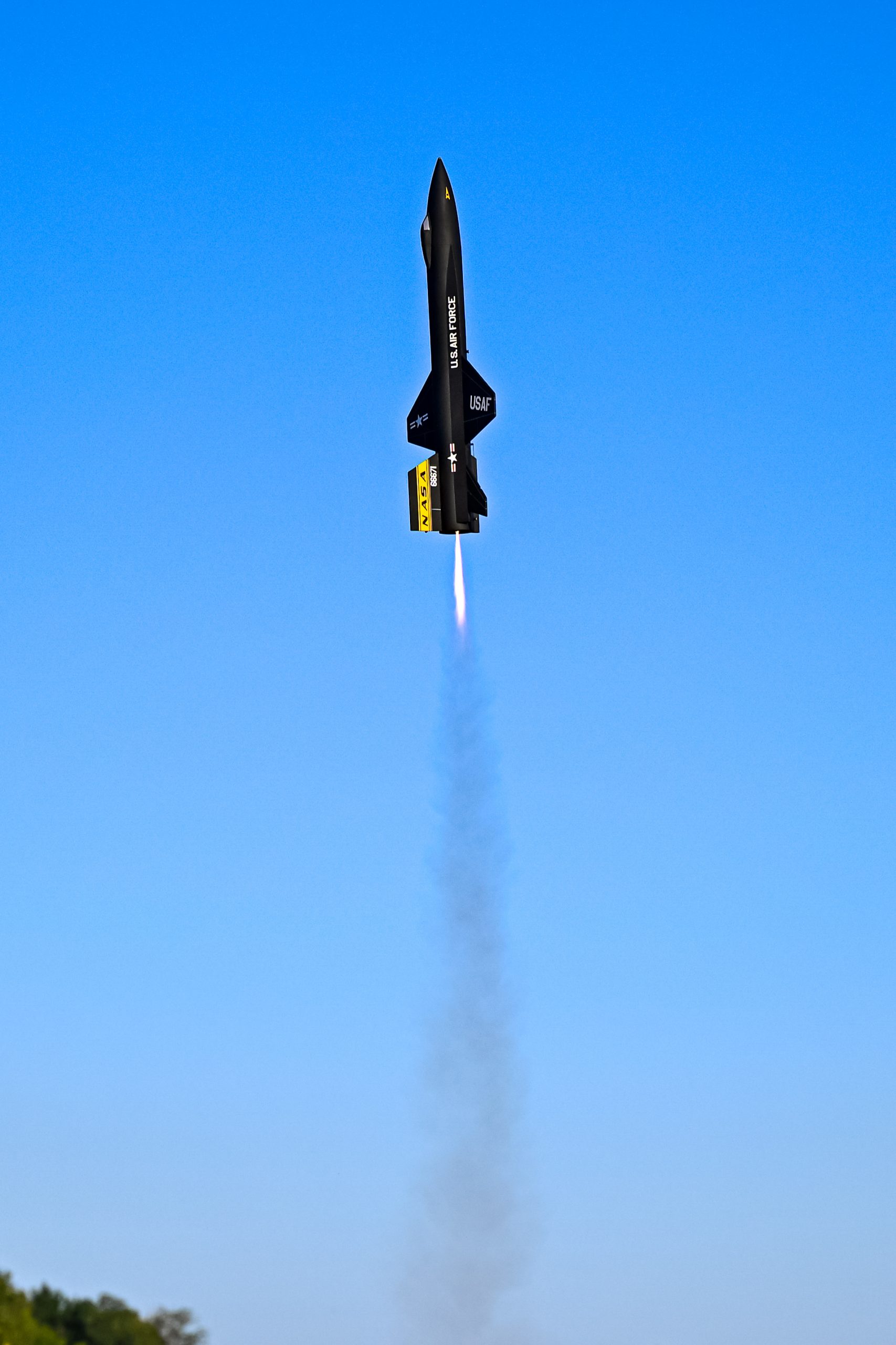
Flying: I recommend using a 5-6′ rail as it guarantees a nice straight boost. See the General Instruction link at the top for flying instructions. Be ready on the first few flights to keep the model straight till you have the trims set perfectly for boost and glide. For this model it will boost fast on the recommended motors. Make sure your First flight trim is neutral and that you do not have the glide “up” trim engaged before every flight.
-
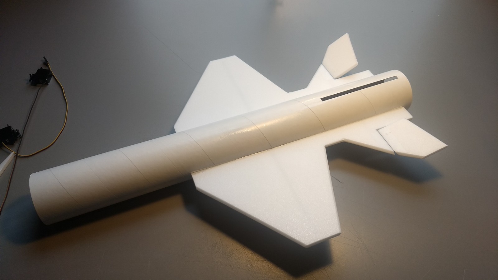
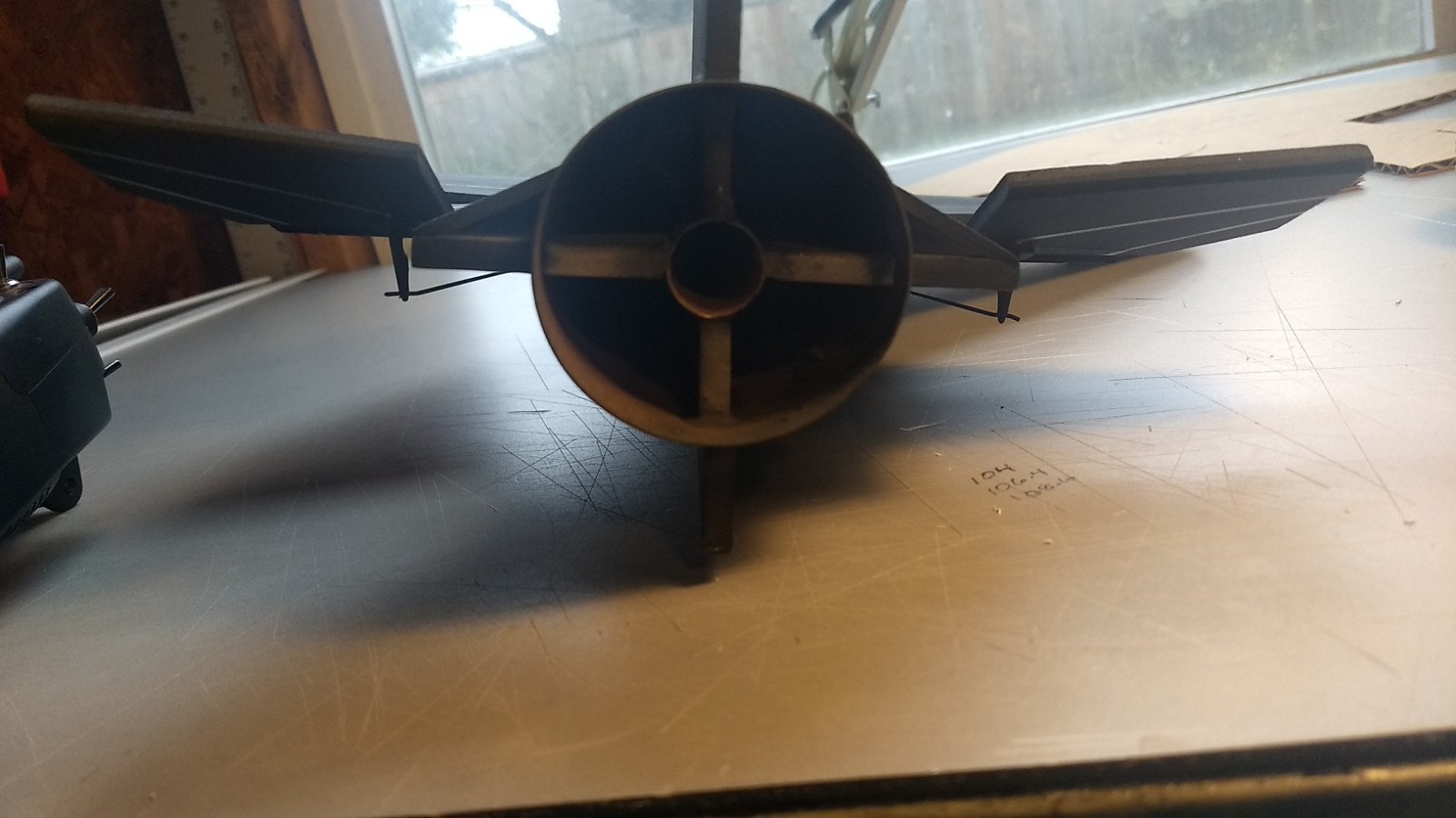
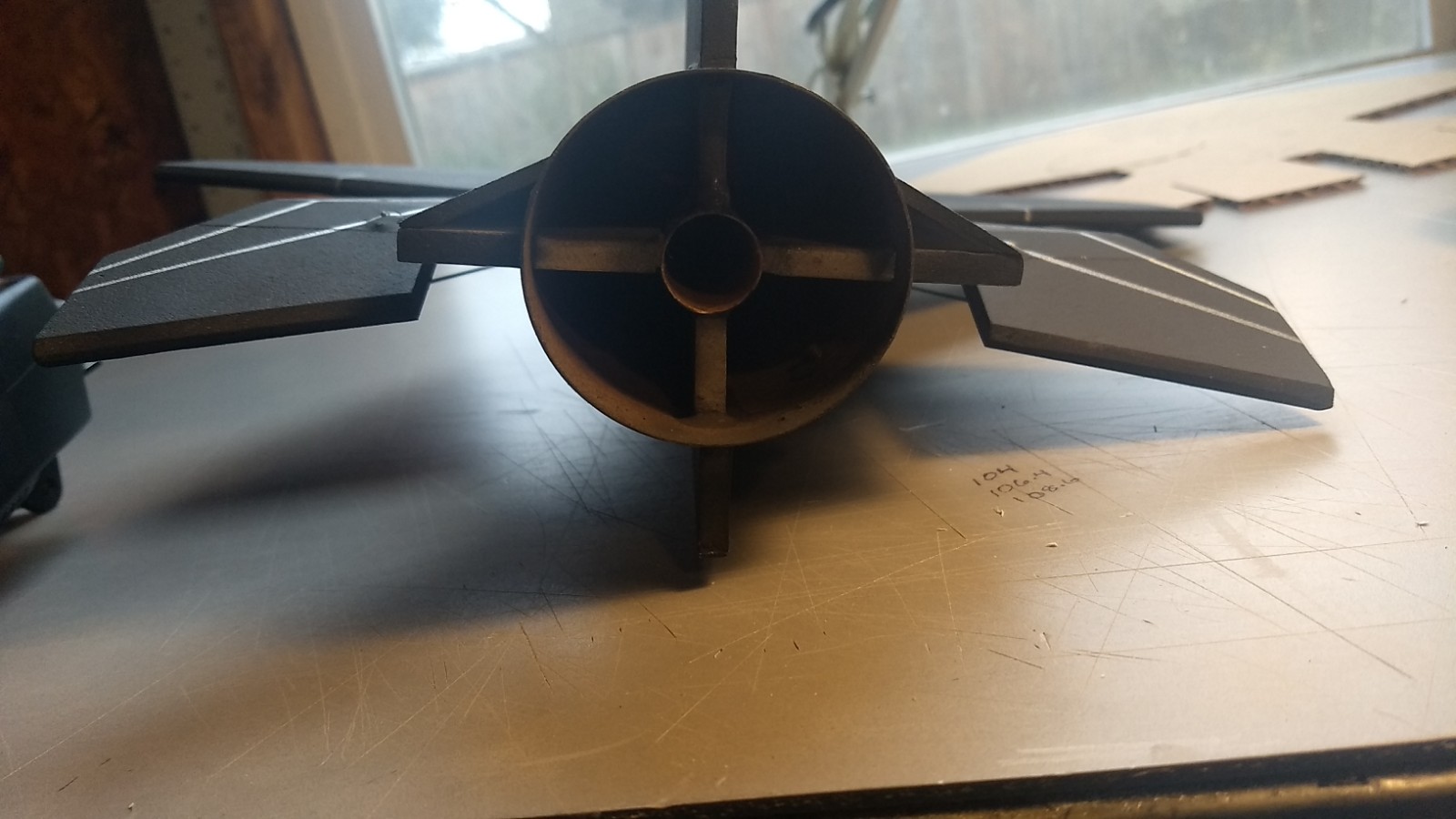
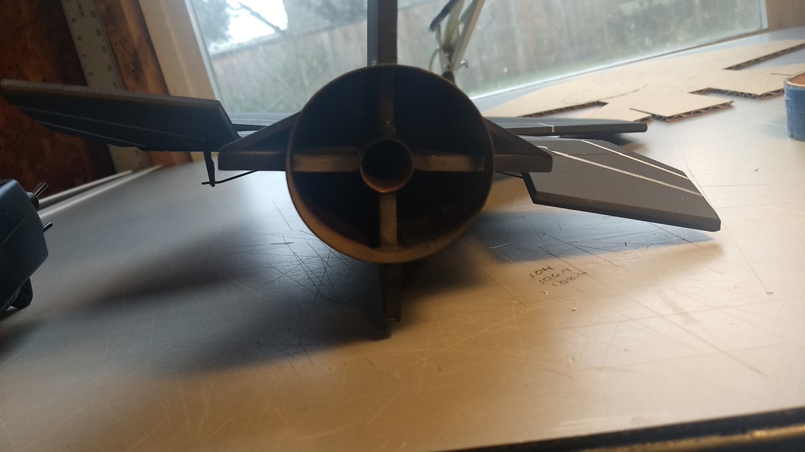
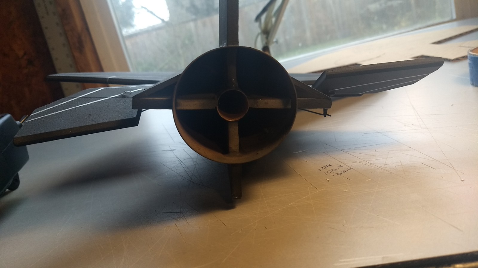
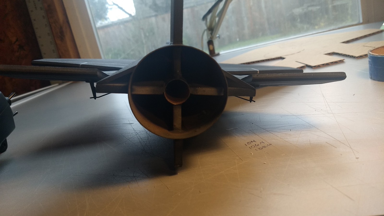
- View showing internal construction
-
- Round window and yellow arrow decal on the nose
-

- Round window and X-15 decal on the nose.
-
- Left side detail showing yellow decal and angled window with shutter doors.
-

- Example of stickershock decals
-
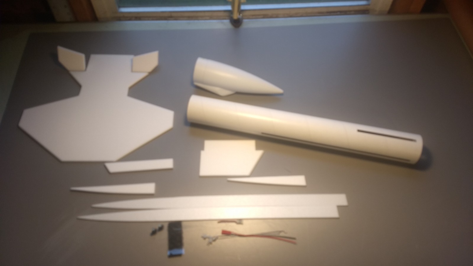
- Main airframe parts
-
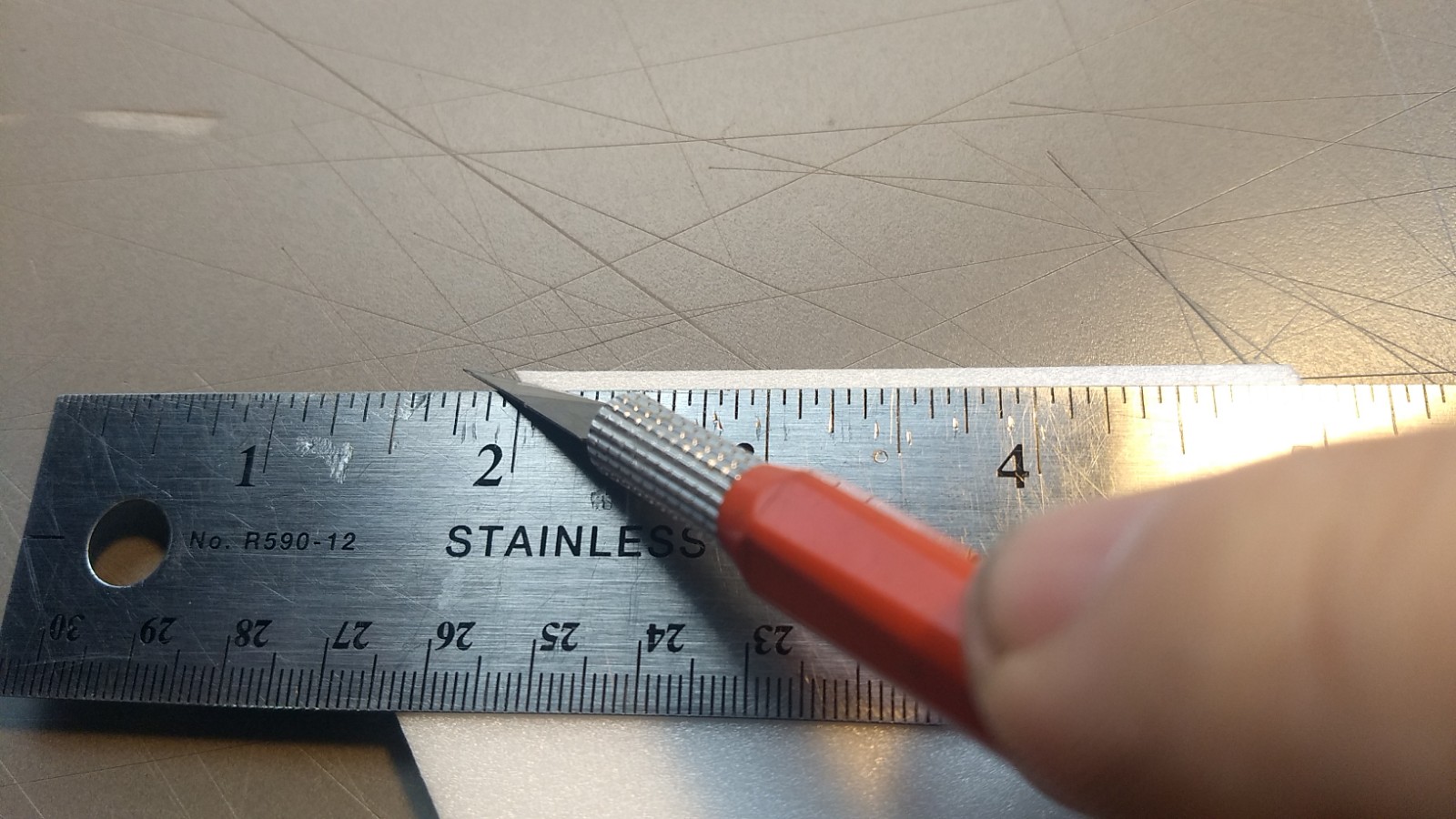
- Beveling the stabilizer and wing edges before assembly
-
- unfold the wing/stabilizer and glue the taped joint and let dry flat.
-
- Insert the wing/stab into the body tube and glue in place when centered front and back. Note the spar is down and the vertical stab slot is up.
-
- Glue in the vertical stab.
-
- Install both front and rear rail buttons in the pre-made holes.
-

- Glue the motor centering tab onto the motor tube keeping it straight.
-
- Test fit then insert the motor tube.
-
- Insert the motor tube fully till it stops, then make sure the vertical stab is still perpendicular to the wing and glue in place.
-
- Glue the styrene strip on the bottom of the ventral fin.
-
- Glue the ventral fin on the bottom of the body
-
- lay the wing against a table and glue the forward chine in place on each side.
-

- sand a bevel on each edge of the chine covers on the side that says “glue” there is a left and right version.
-
- Glue the rear of the chine covers against the wing and tail.
-
- Pull the front down and make contact with the front of the chine and the body tube. Glue to the chine at this time.
-
- Glue the top of the chine cover to the body tube then trim them at the front and rear to match the chine and and lightly dress with sandpaper
-
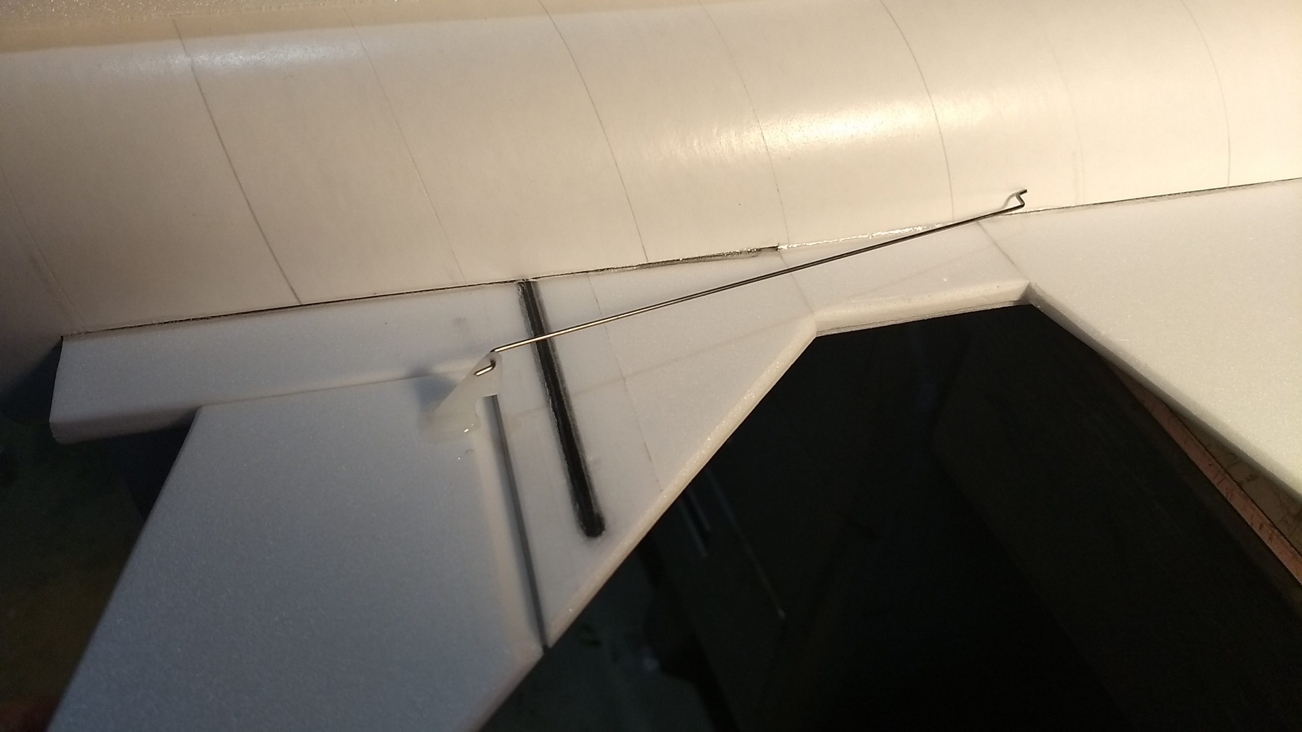
- Install the pushrods into the bottom of each control surface, pushrod closest to the body tube
-
- Showing pushrods installed and how they angle inward on each side.
-

- Put some glue on the top of the prongs of the control horn to lock it in place.
-
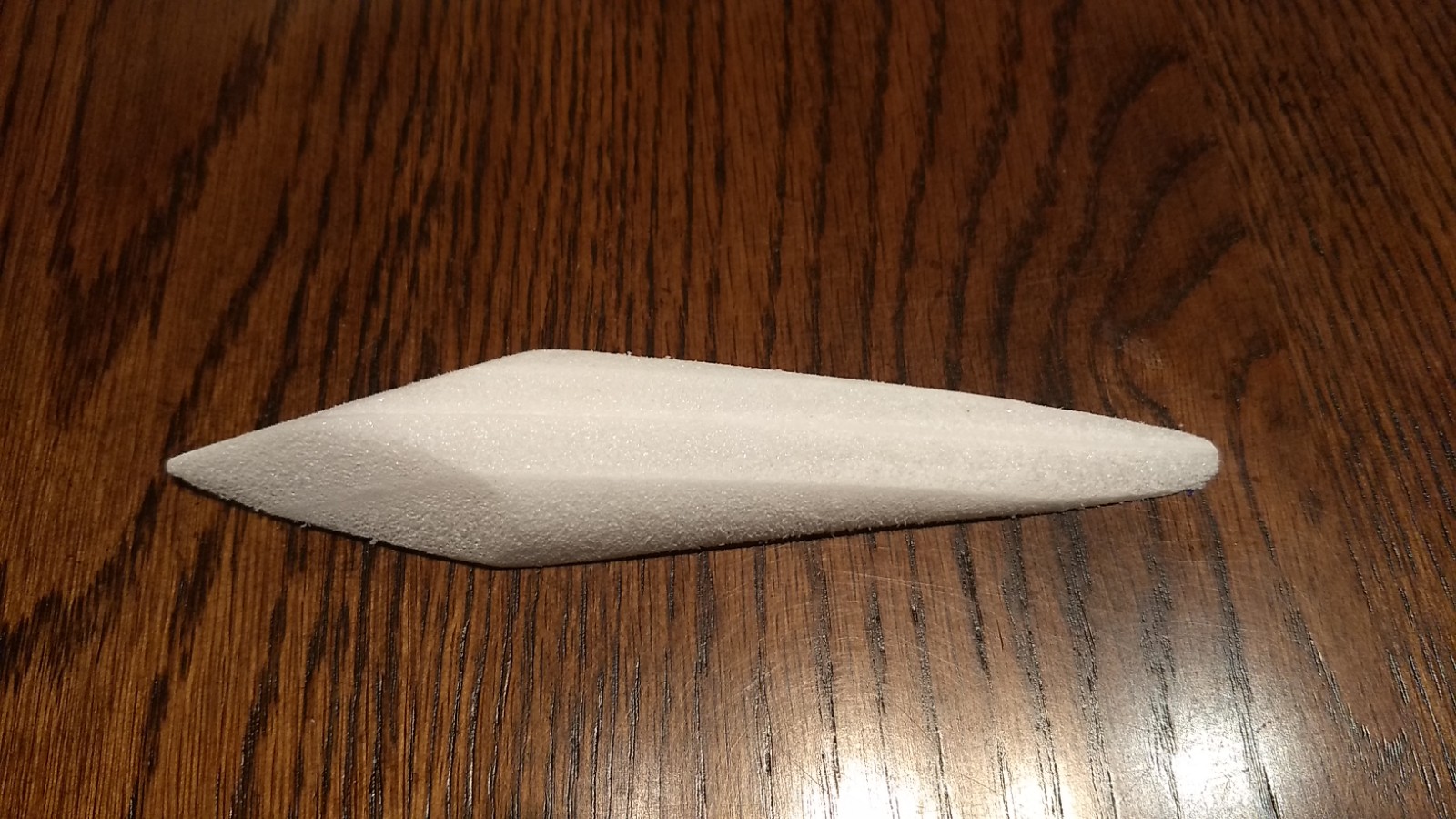
- Laminate the four cockpit pieces, then use the included template to shape and sand the cockpit to shape.
-

- Lay sandpaper over the nose cone and body tube and gently sand the bottom of the cockpit till it conforms to the shape of the tube and body.
-
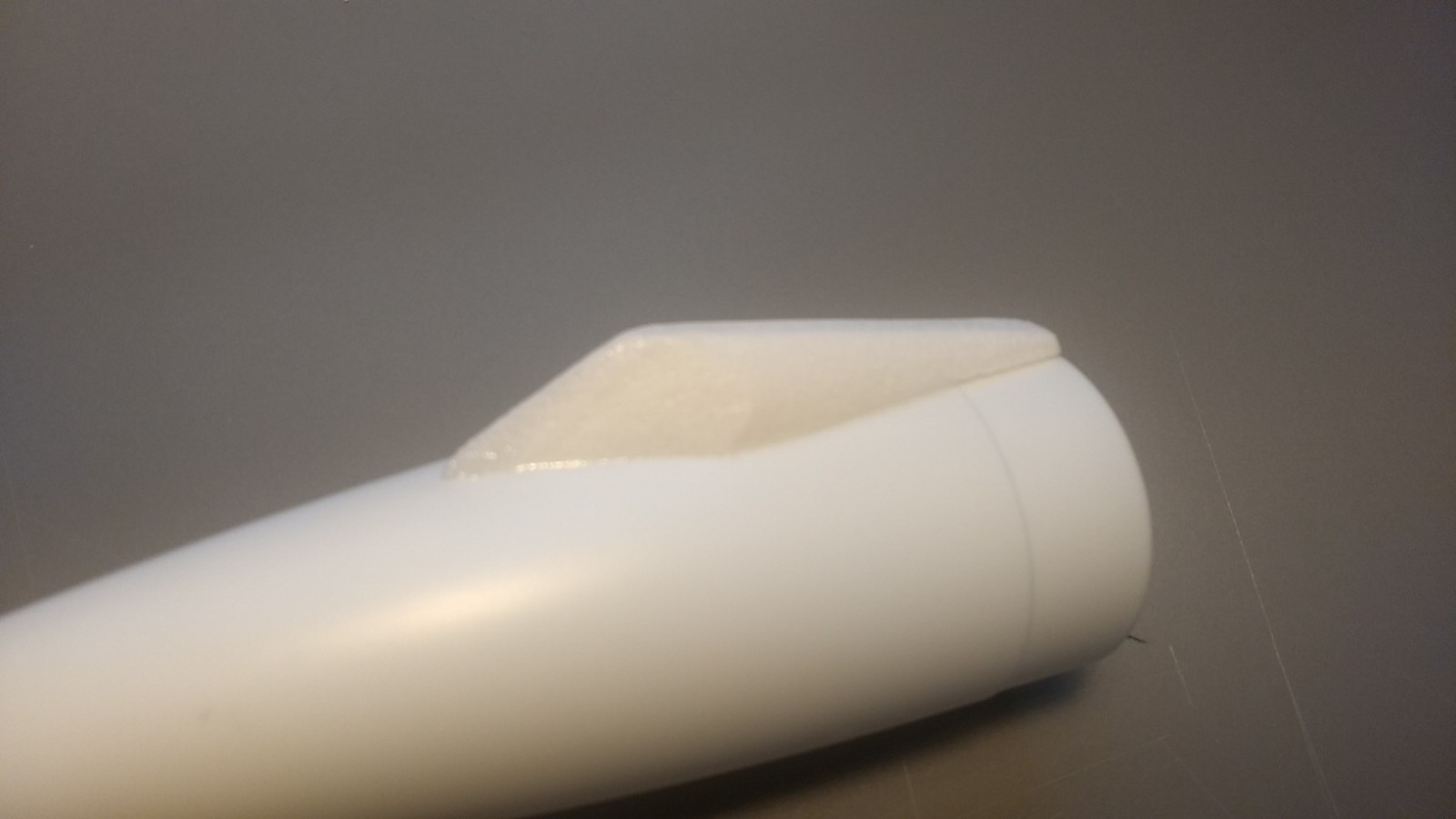
- Cockpit glued to nose cone, rear of cockpit should be even with the front of the nose cone shoulder, this photo shows it further back but it looks better more forward.
-
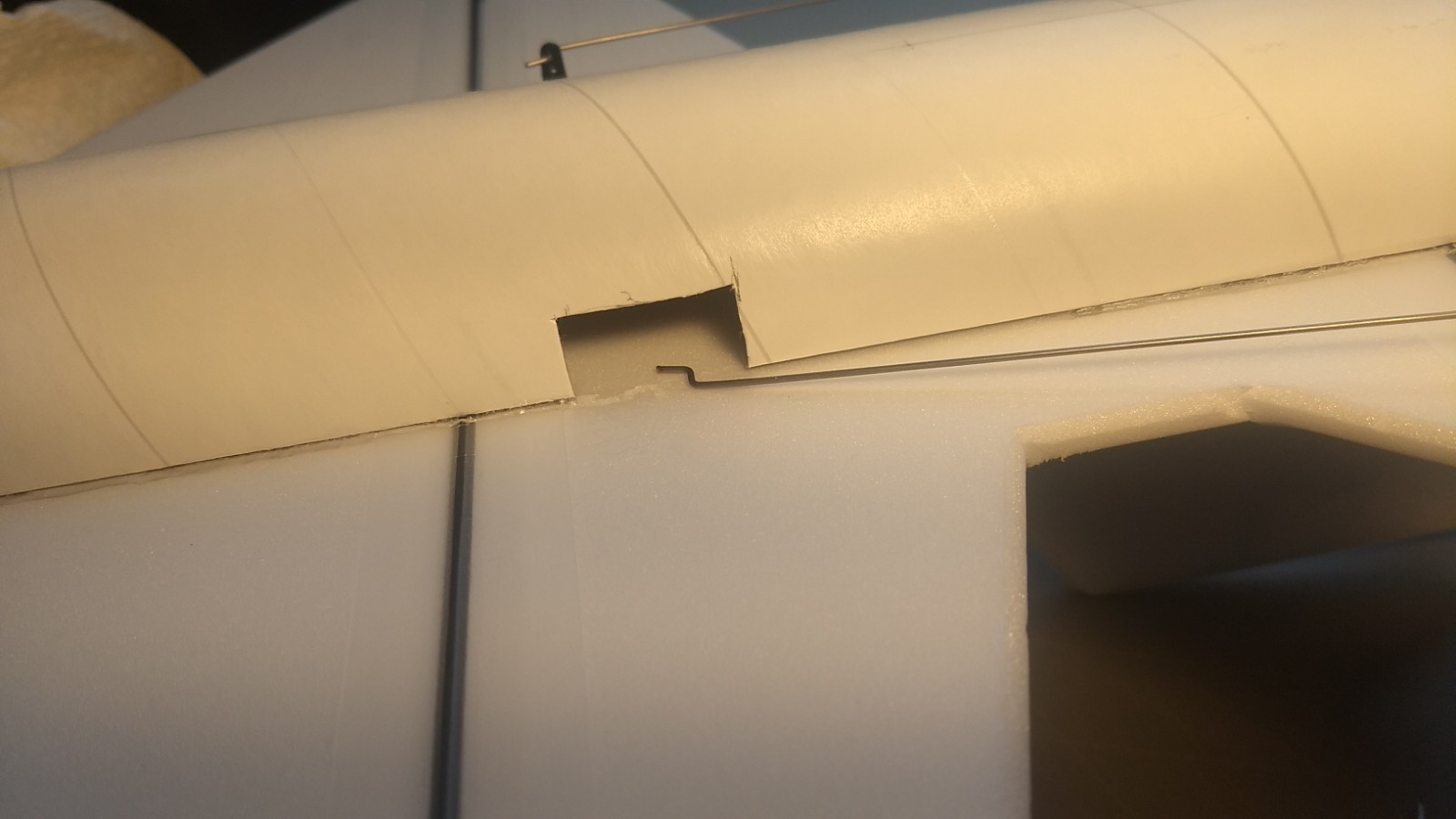
- cut a pocket for each servo.
-
- route the servo wire out the back of the model on the same side of the lower motor mount tab, then connect to the receiver and power up the radio.
-
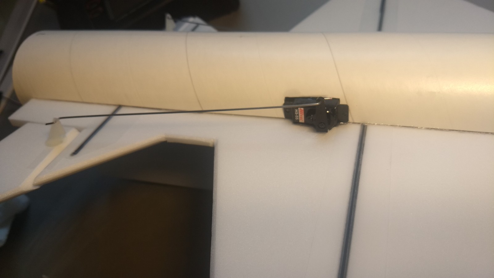
- Glue each servo in place flush with the body tube and keeping the stabilizer level. Push the receiver and battery and wires forward and attach the receiver about 1.5″ back from the end of the body tube and mount the battery inside the nose cone shoulder.
-
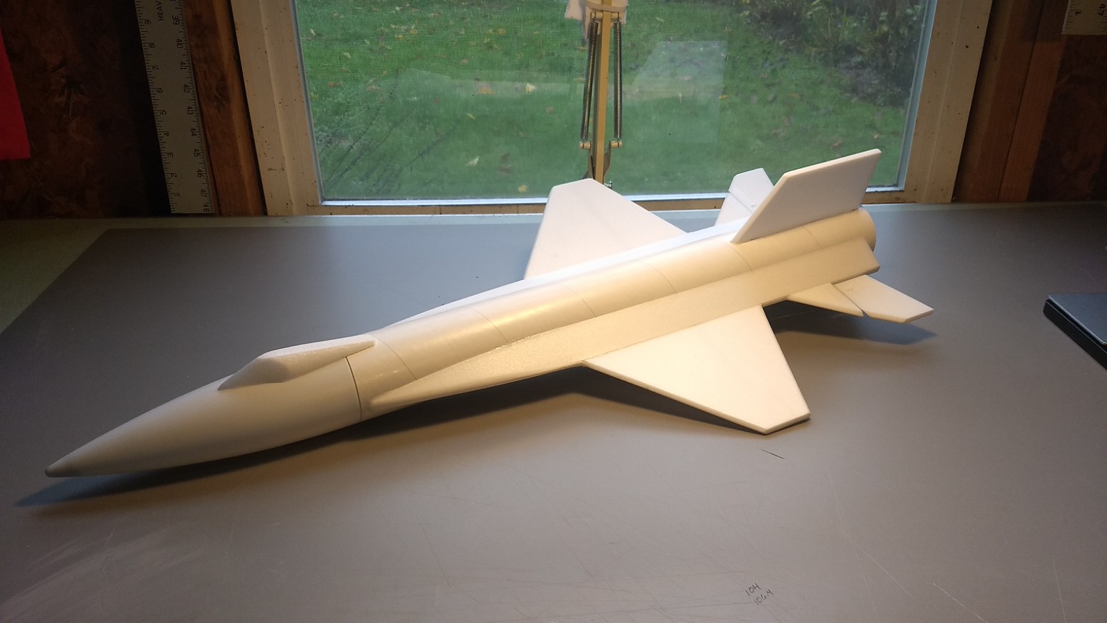
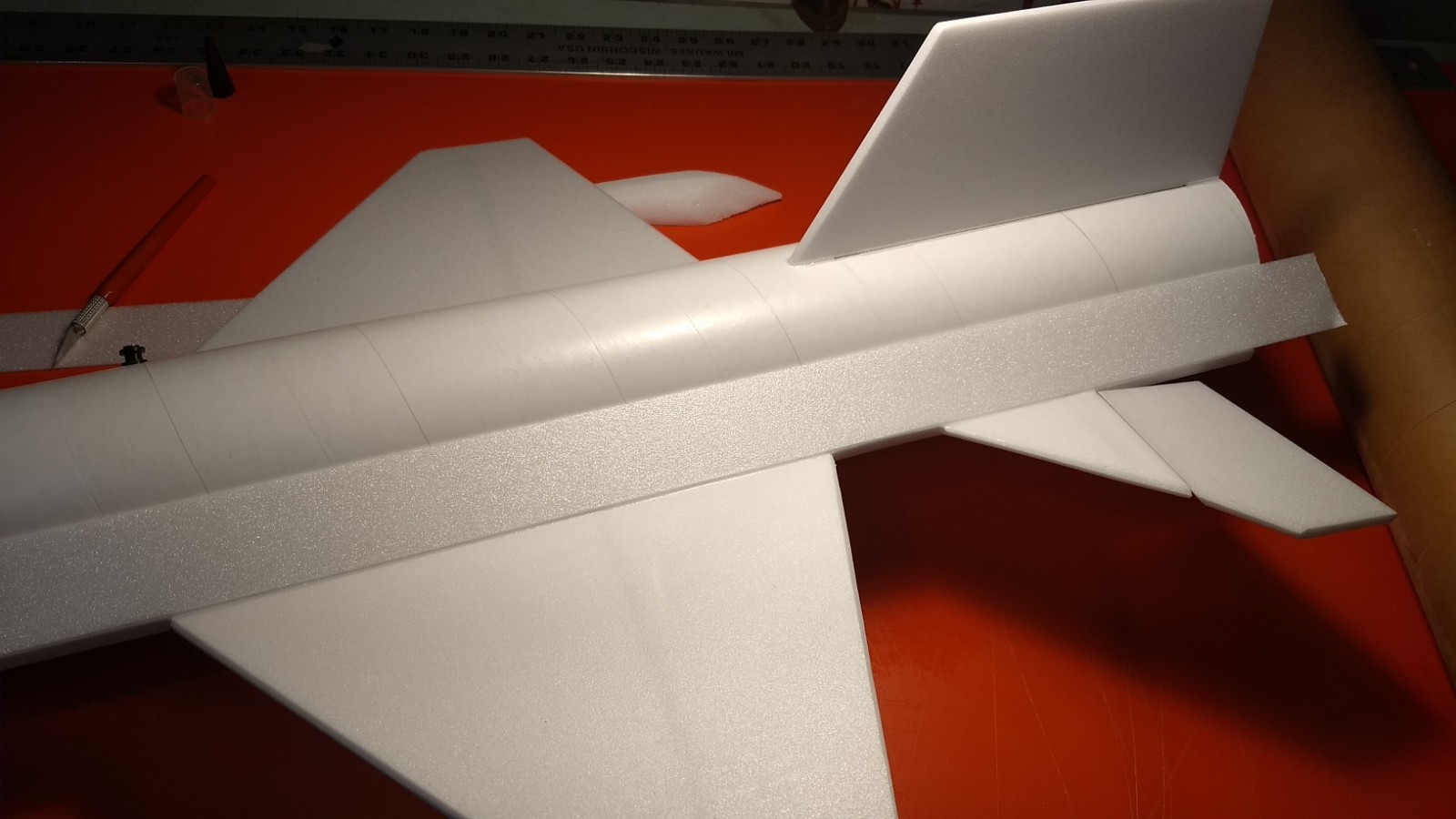
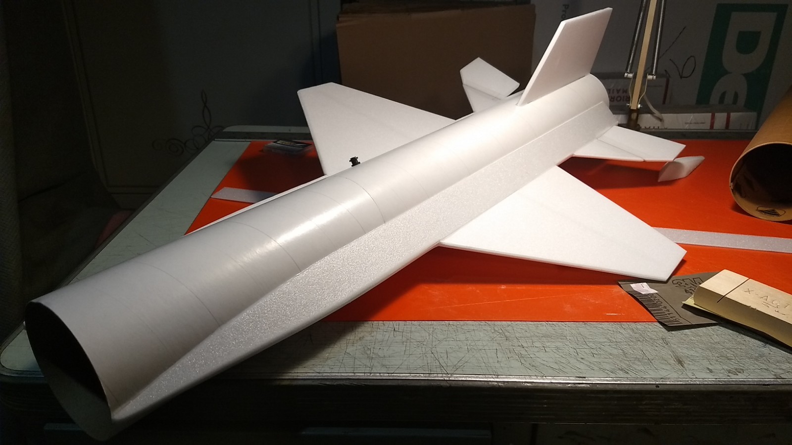
- Airframe complete.
-
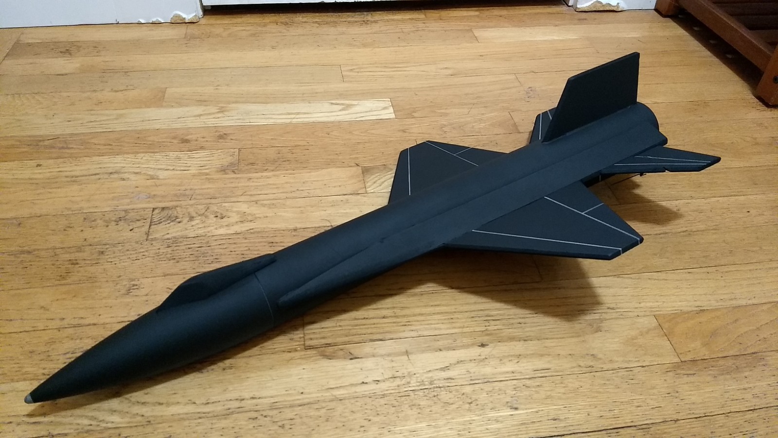
- Model painted and panel lines applied with silver sharpie
-
- Up elevator
-
- Down elevator
-
- Left aileron
-
- Right Aileron
-
- Glide Trim
-
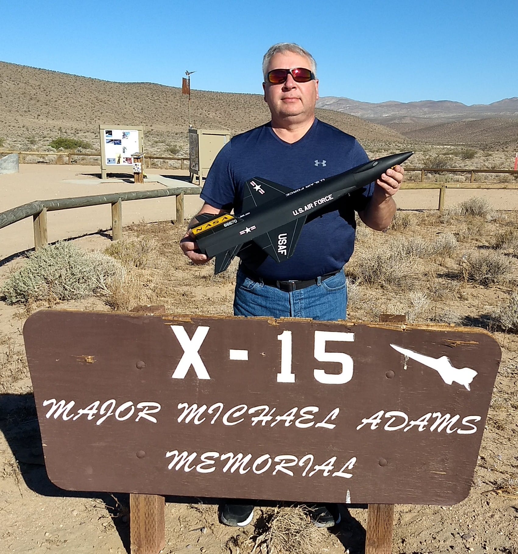
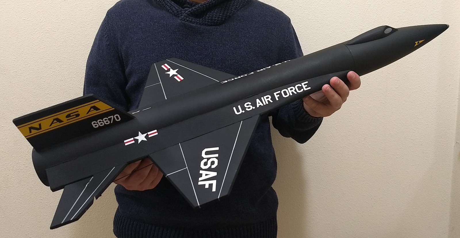
- Completed model
-
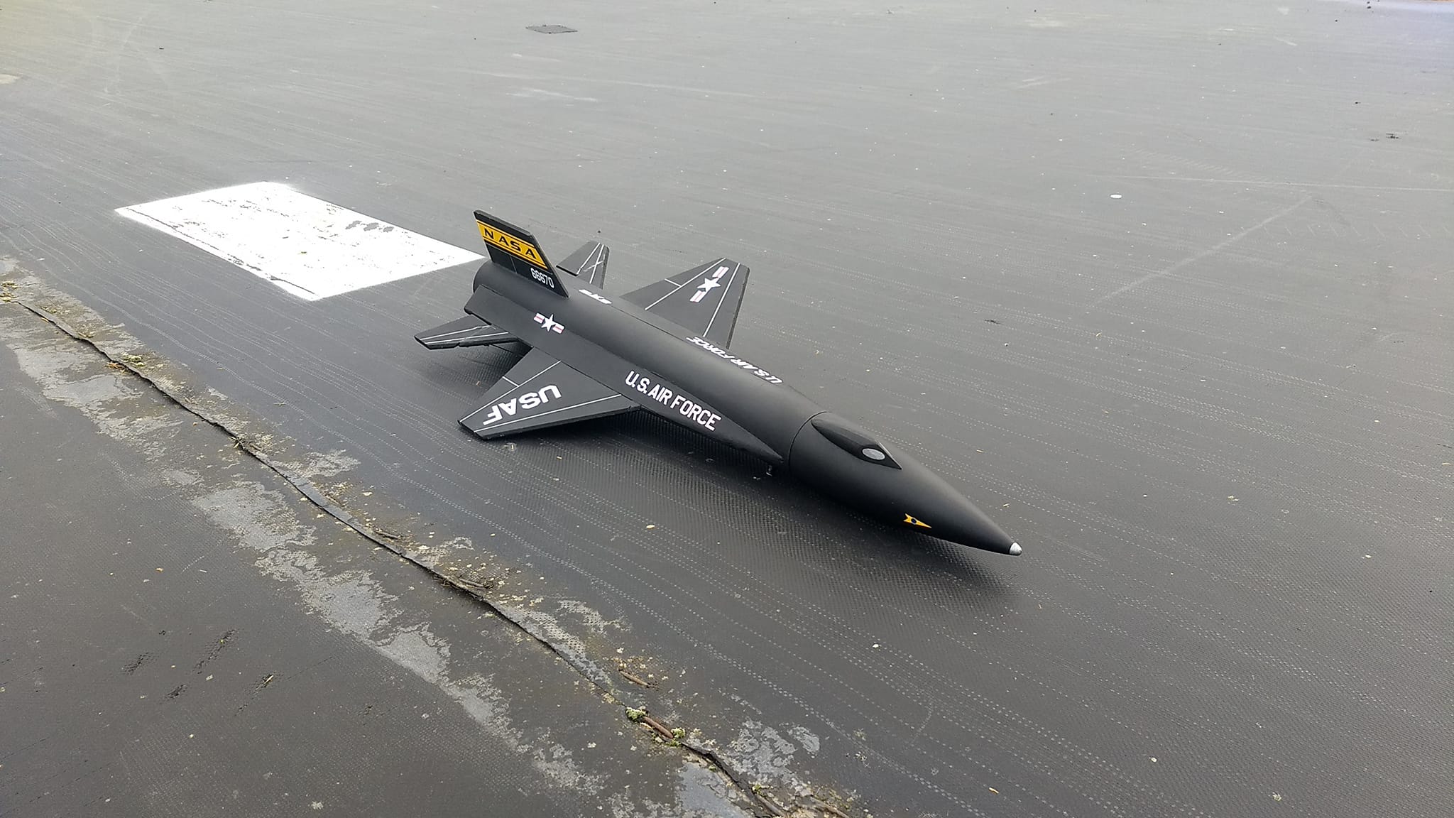
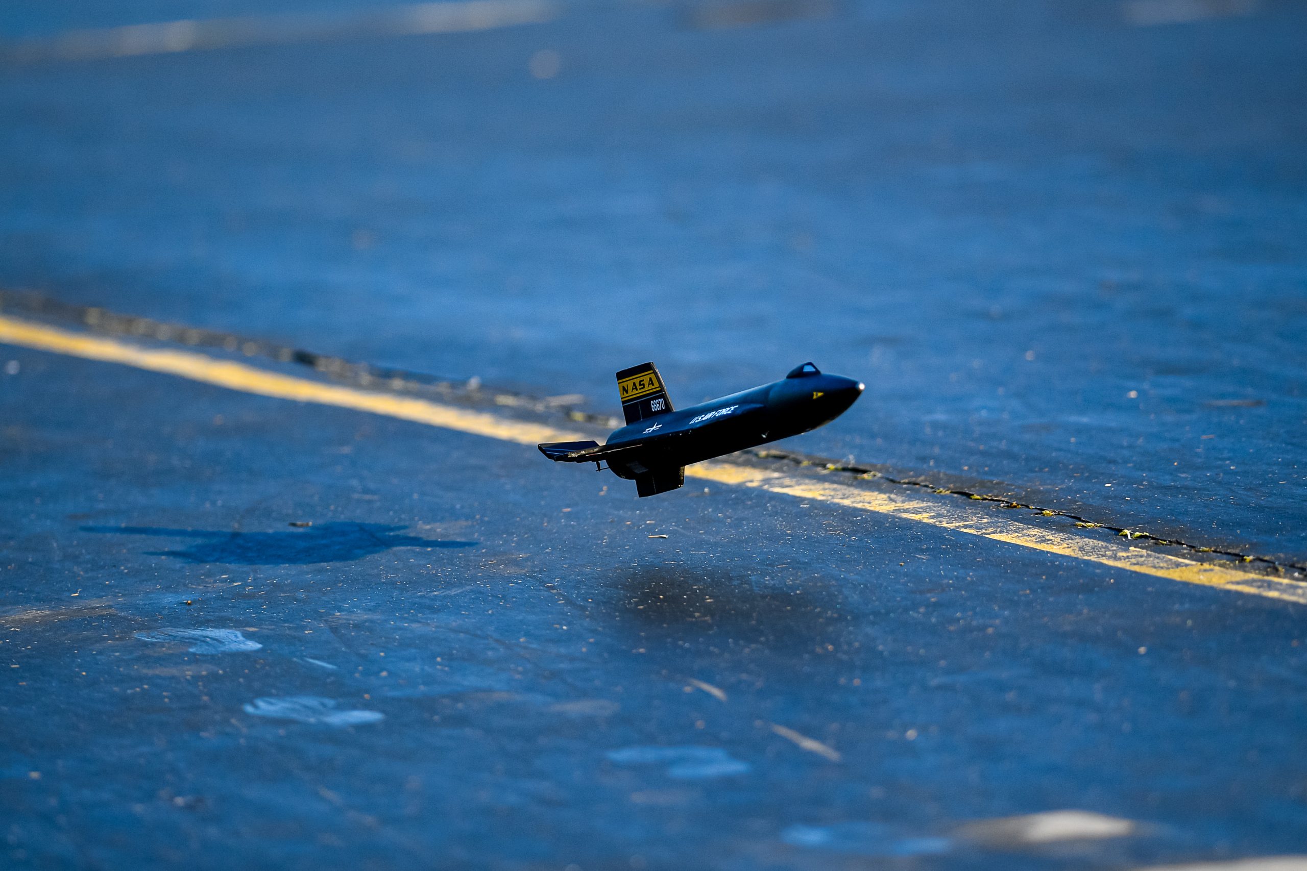
- My Original prototype Tail number 66670 after it’s 76th flight.
-
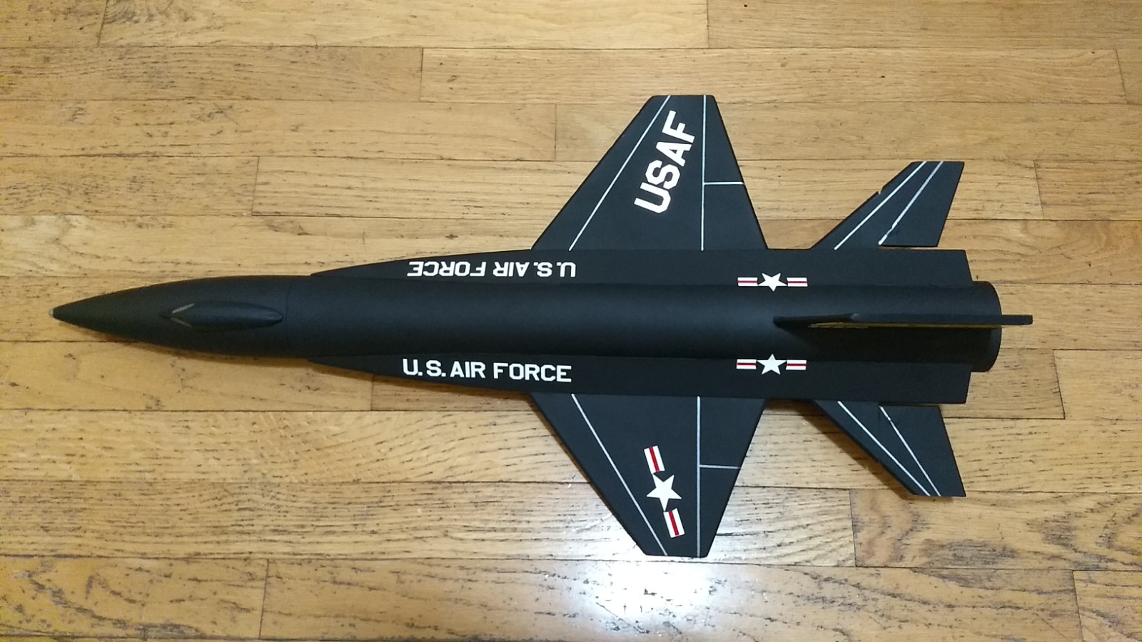
- top view
-
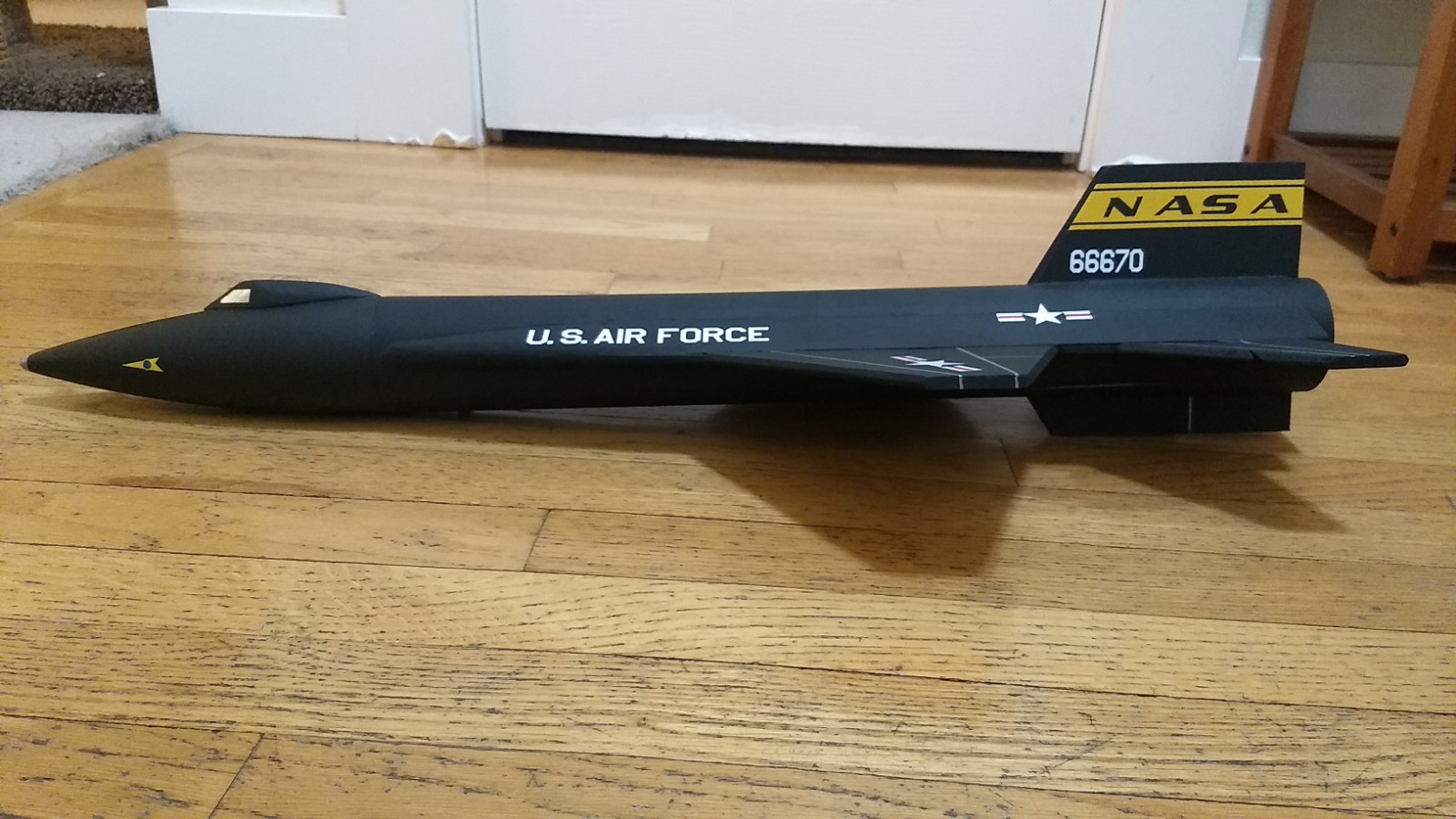
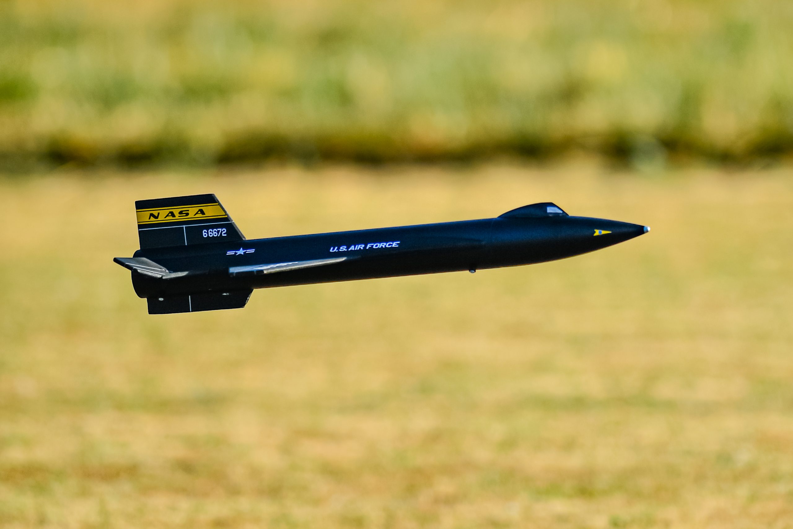
- side view
-

- rear quarter view
-

- quarter view