
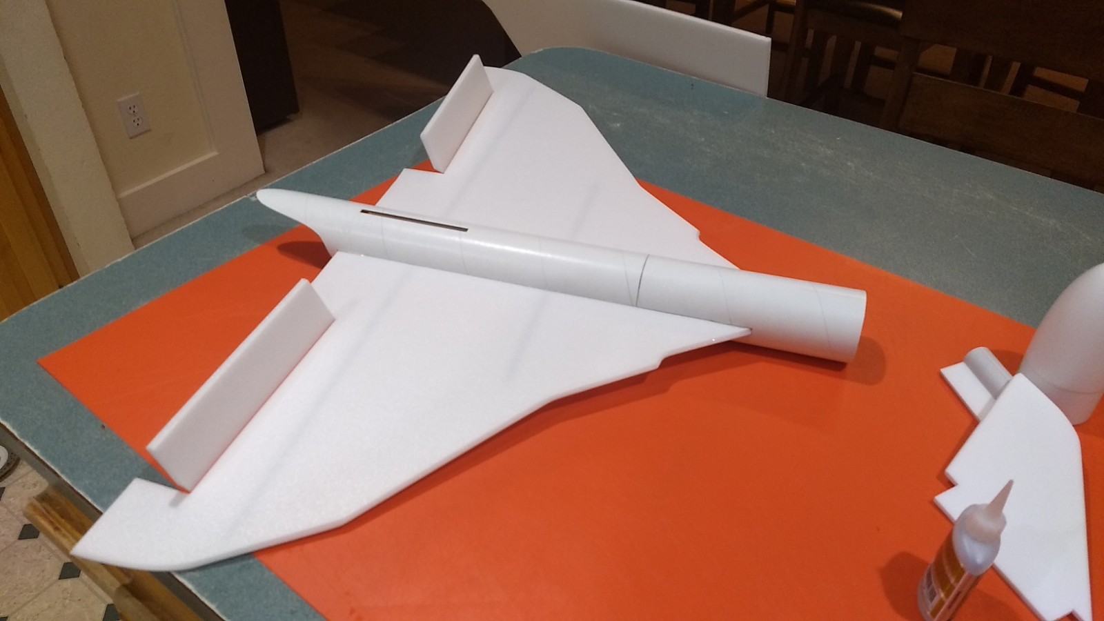
Completed model
The Vulcan RC Rocket glider kit is modeled after the classic cold war British nuclear “V” Bomber. It features a pre-cut body tube with tail, wing slots, and tail “stinger” pre cut. It has a light wing loading giving it a very nice glide and easy/stable boost. It comes with a plastic nose cone, 2.6″ white tubing for the body and 9mm depron wing and 6mm tail surface, cockpit and dummy motor detail. Construction is very simple and takes about an hour and a half. Elevons are pre-hinged, the rail button holes are pre-cut. The wing spar slots are pre-cut. You will need two 10 gram type servos, two 12″ servo extensions, a receiver, and a small 500mah single cell lipo battery. You will need a transmitter with delta or elevon mixing. Length 28″, wingspan 30″, weight rtf 10.25 oz. High quality cut vinyl decals from Stickershock are available HERE
CG location for rocket flight: 8.25″ forward of the trailing edge of the wing at the body tube.
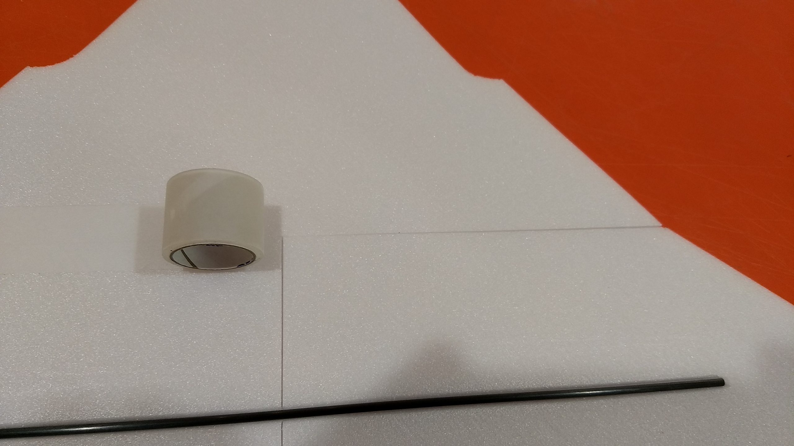
Identify all pieces, the kit should contain:
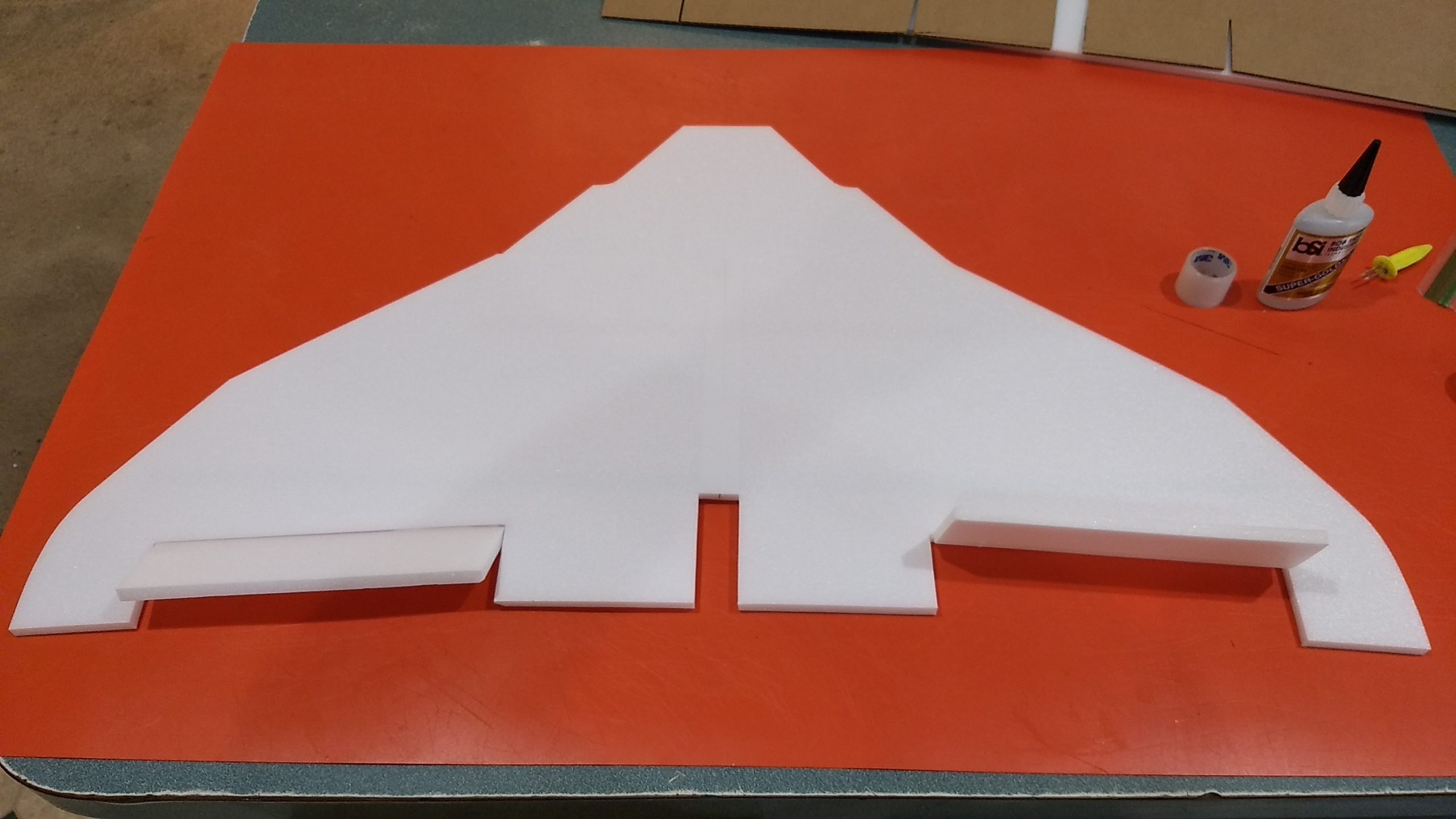
1 wing taped together
2 rail buttons with t nuts
1 long wing spar
1 short wing spar.
1 Motor mount
1 Nose Cone
4 Foam engine details
1Body Tube
1Vertical Stabilizer
3 cockpit pieces
2 control horns/Pushrods
1 motor mount centering strip 6mm by 2.75 by 13/16″
Velcro(for battery and rx/bec attachment)
3M blenderm tape
Lead weight
Spare depron
Notes before starting:
Reference to CA+ means foam safe CA+, normal CA+ will melt the foam! Normally you need to use accelerator to get the CA to set on the foam since there is nothing for it to soak into and activate.
Epoxy is not needed in this model. Weight is critical and the model is designed for the thrust and flight loads. Weight in the rear end is bad and will require additional weight in the front of the model.
I’ve found that rather than sanding the wing and tail leading and trailing edges to simply use a thin straight edge and exacto knife to cut a 1/8″ bevel cut on the top and bottom, it’s quicker and less messy and less prone to tear an edge of the foam. On the tail cut a 1/16″ bevel. For the rounded portions of the wingtip and stab, the cockpit assembly and motor details you can use 320 or 400 grit, a sanding block and a very light touch. Do this before assembly.
Assembly:
- Glue the centering strip on the motor mount on one of the lines on the motor tube.
- Install the rail buttons in the pre-made holes at this time.
- Soak the rear of the body tube stinger inside with foam safe CA to help harden it and protect it from handling damage.
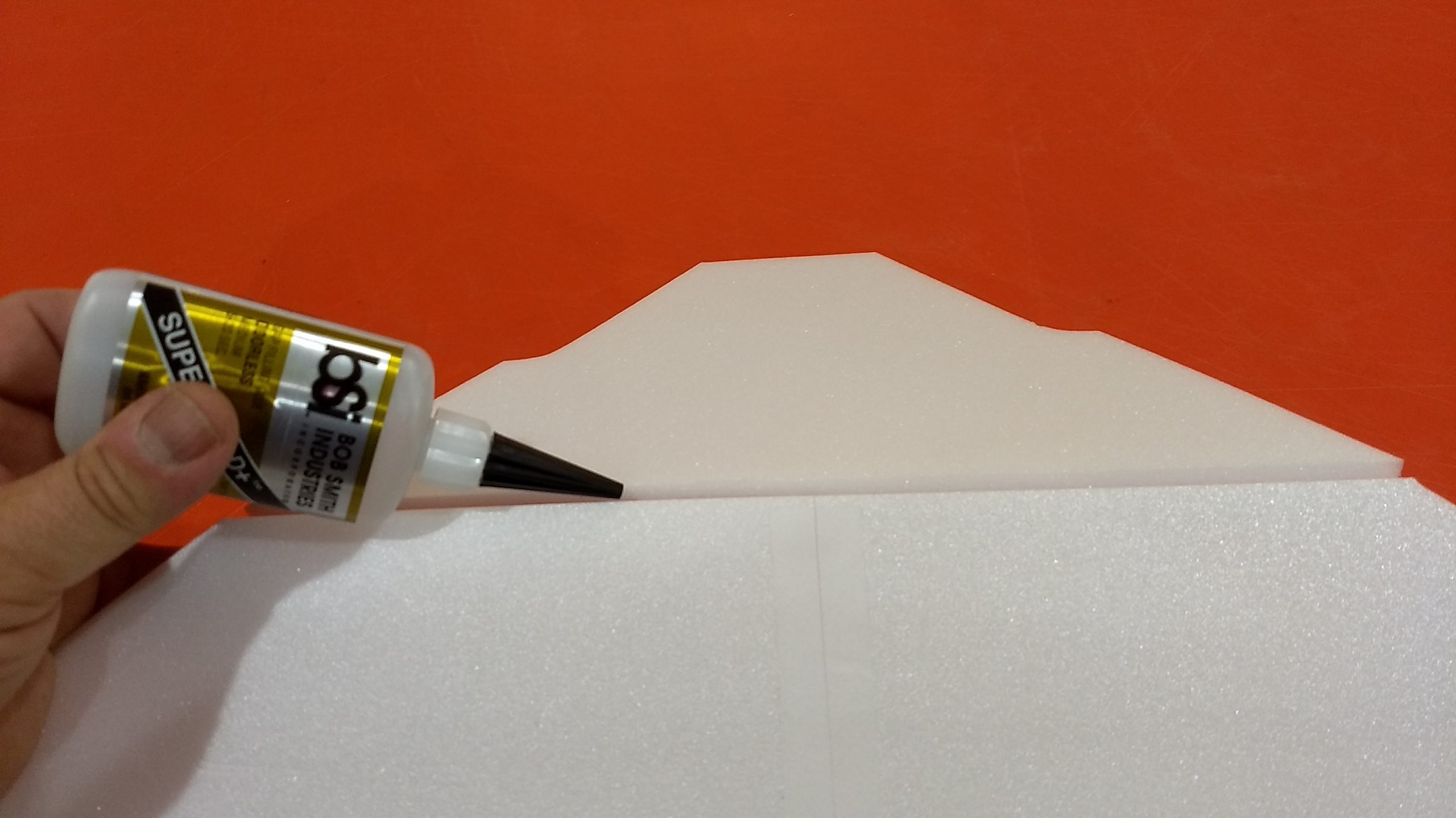
- Unfold the wing and glue the center long fold joint using CA+ and accelerator, make sure it is flat.
- Glue in the two spars in the pre-cut slots, then tape over the spars and long wing joint with blenderm tape.
- Apply blenderm tape accross the bottom of the front horizontal wing fold joint(only half is taped on the bottom so it would fold to fit in the box), then glue that joint flat as well. Apply blenderm tape to the top of the joint if you wish, although this is a low stress area you may feel more comfortable taping it on the top.
- Test fit the wing in the slot in the rear body tube, if it is snug, sand or trim as you don’t want it to drag/damage the wing as you are inserting it. Note the rail buttons are on the bottom of the model and the spar will be pointing down on the wing.
- Make sure the front and rear of the wing is centered in the slot and tack glue it at the front and rear top and bottom and make sure it is set. Then apply a fillet on the bottom of the wing/body tube joint, then flip over and do the top. It may be helpful to squeeze the tube in the middle as you go and hold it till the glue sets, as the tube tends to flatten once the wing slot has been cut.
- Glue the vertical stab in place in the slot make sure it is perpendicular to the wing.
- Test fit the motor tube in the rear of the model, You may need to sand the foam tab slightly till it will insert easily. The tab will be on the bottom and the sides will be centered by the recess in the wing. The tab on the stabilizer will be on the top of the tube to locate it. Run glue on the top and bottom motor mount tabs, wing and stabilizer tab to glue them to the motor tube. You don’t need a lot of glue here as the motor pushes against the rear of the wing which is glued in its’ slot so it can’t really go anywhere. For flight you can use a tiny bit of tape to keep the motor from falling out after burnout.
- Glue the three cockpit pieces together, then sand/carve it to a 45 degree slope at the front and to a taper at the rear and then round the corners. Wrap a piece of sandpaper(220-320 grit) around the body tube at the front with the nose cone installed and gently sand the bottom of the cockpit so it matches the radius of the cone/body tube. tack glue the cockpit centered between the cone and body tube joint. Be sure not to glue the cone to the body tube!! Once set, slice the cockpit at the body tube/cone joint so they can separate then apply fillets to the cockpit on each piece.
- Glue the four motor detail pieces to the wing. Glue them so that 1/2″ of the rear is hanging off the rear of the wing. Glue the first one 1/2″ inboard of the inboard elevon surface cutout, glue the next one about 1/4″ inboard of the first one. Repeat on the other side.
- Glue the control horns in place on the bottom of the control surfaces, the holes face forward and the pushrod should be closest to the body tube.
The basic construction is now complete.
Radio Installation
Note: Your radio needs to be configured for Delta mixing, this means that the servo arms will move the same direction during elevator stick movement and opposite for aileron stick movement. Connect your servos to the receiver one in the aileron connection and one on the elevator connection and apply power. Use a servo arm at least 9/16” long and with holes small enough that there won’t be slop with the pushrod wire when installed. I use the hole furthest out on the servo arm, to maximize movement. On some servos there are a long two-ended servo arm, you can trim off one end if needed to get sufficient length. Zero out any trim settings on the transmitter. The model once the motor has burned out is nose heavy and flying wings lose pitch authority when nose heavy so you want as much up elevator travel for trim/flare as possible.
- Connect a servo to each pushrod. If the pushrod is too tight, you can use twist an exacto knife in the servo arm hole to make it larger, but be careful and do not make it too large. Once connected, tape each servo in place so that the control surfaces are centered. Flip the model right side up and look at it from the rear. Moving the transmitter stick back(up elevator) should move both elevons up. Moving the transmitter stick to the right should move the right elevon up and the left elevon down. If you can’t get the servo reversing to give you the right polarity try swapping aileron/elevator inputs to the receiver or turning the servos over and swapping the servo arms to the other side of the output shaft. If that is correct, continue.
- Flip the model upside down and supported. The servos may be attached to the model using double back servo mounting tape(not included) or by directly gluing the servo to the wing with CA+ or a small amount of epoxy. Double back servo tape can loosen over time and with exposure to heat, I prefer to glue the servo in place. With the radio still on, put a small amount of glue on the servo, being careful not to get any near the output shaft. And set it in place on the model keeping the control surface centered. Do the same to the other side. Make sure the glue is set before continuing. The servo will be near the middle of the wing. If there is any warp in the wing tip area, align the outboard edge of the control surface. The wing is cut so that any warpage in the foam sheet should be symmetric and will not affect any flight performance, any roll/pitch will be trimmed during test flights.
- Flip the model back right side up. Make sure the control surfaces are centered, use trims if needed. Now measure the control surface movement. Full elevator movement should be 1” in each direction, aileron movement should be 1/2″ in either direction. Since the model will be nose heavy, extra elevon movement helps to give sufficient authority during glide.
- If you have a flap/elevator mix you can program up elevator to a switch setting. The model needs approximately 3/16″ to1/4” of up elevon during glide. If you can’t set the up elevator trim to a switch on your radio you’ll have to manually put in boost and glide trim which is hard to do while flying the model.
- Attach a 12″ servo extension to each servo.You just need to be able to route the wire to the front of the tube to attach it to the receiver.
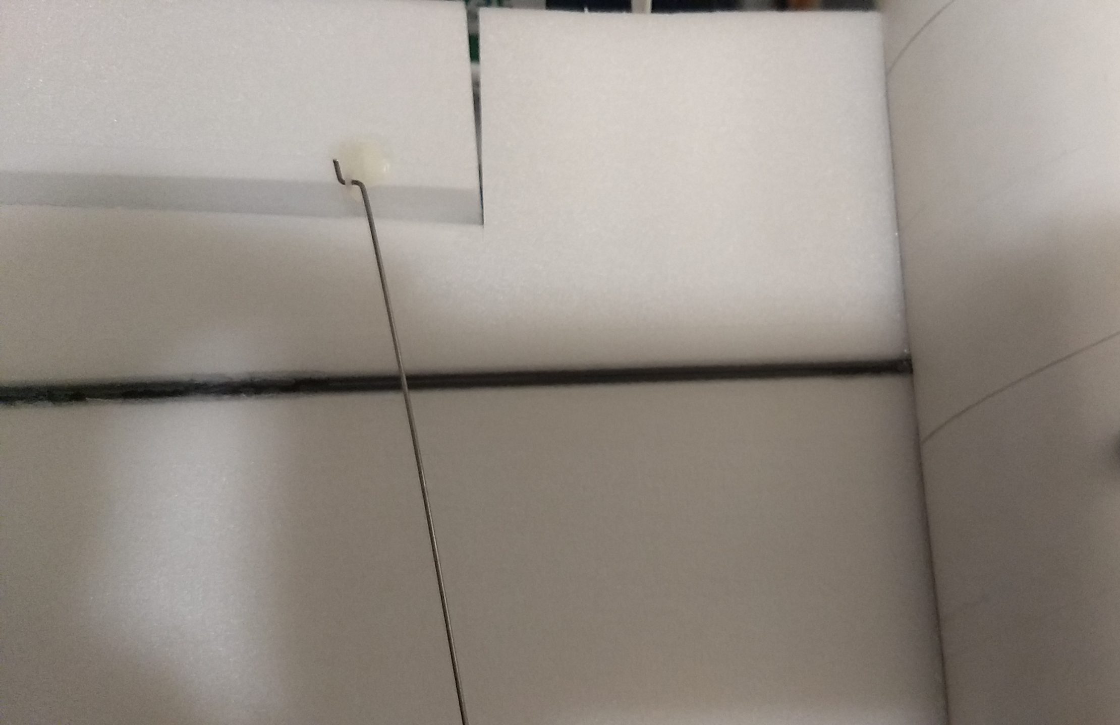
- Make a 1/8″ wide by 1/2″ long slot in the bottom of the wing/fuselage on each side and pass the wires through to the inside and toward the front. On my model I just made a U shaped cut, folded the cardboard forward, inserted the wire then folded the cardboard back over the slot/wire. I then taped over that with blenderm tape to avoid having a large open slot. See photo for more clarity. You can also just cut the slot out completely and cover it over with tape after inserting the wire. Tape the servo wires down to the wing as well.
- Attach the servo wires to the receiver and make sure they are going the right direction.
- Use the included Velcro to attach the receiver inside the front of the body tube recessed about 3″ to clear the nose cone shoulder.
- Use the included velcro to attach the battery inside the shoulder of the nose cone or inside the body tube as needed ( it may be desirable to wait to place the velcro to see how the balance is, I was able to avoid nose or tail weight by simply moving the battery slightly by an inch or two then applying the velcro)
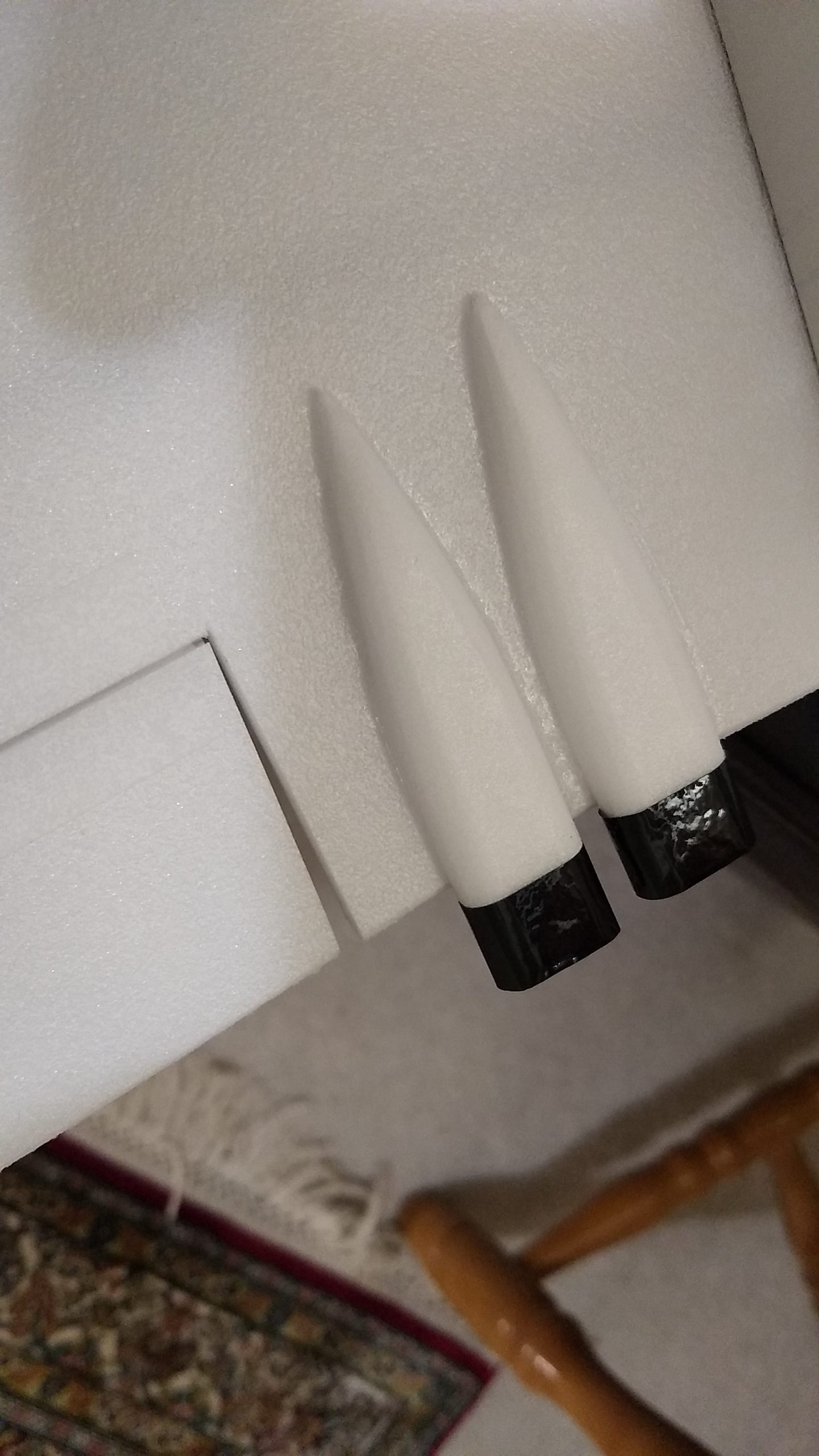
- If you paint the model, make sure you test it on scrap foam first. I chose a white scheme so only hand painted the tip of the stabilizer, and the bottom front of the nose cone radome area. I hand cut self adhesive vinyl for the cockpit, roundels, tail markings and wing engine intakes, Click on this link to download the templates. [Download not found] Or use the link above to purchase the stickershock pre-cut vinyl decals if you wish.
- If you are going to fully paint the model with camoflage etc, this will add approx 1/2 ounce to the flight weight. Make sure no paint will get on the servo output arm or the rail buttons. I only use Model Master(testors) or testors enamel small rattle cans for painting directly on the foam and cannot recommend any others as you may melt the foam. Do not spray too close or too thick as the solvents can damage the foam, spray in light coats.
- If you use trim vinyl decals, it helps once applied to use a hair dryer on hot to soften the material and then push it down onto the model with a towel. It helps it conform and stick much better, especially on painted surfaces.
- Insert your heaviest loaded rocket motor into the motor mount
- Support the model at the balance point indicated for boost. I use two pencils with the erasers pointed up and the erasers ends pointed to protect the ting, held in place by two small vices. Place the model on the pencil erasers on the balance point indicated above. Use the included lead weight as/if needed to balance it. Do not try to fly the model with it balancing it behind this point. The adage is, a nose heavy model flies poorly, a tail heavy model flies once. Make sure you do this after you painted your model as this will add tail weight.
Flying: See the General Instruction/Information link at the top for flying instructions. Be ready on the first few flights to keep the model straight till you have the trims set perfectly for boost and glide.
-

- Glue the centering strip to the motor tube on one of the marked lines, rest of major parts shown here as well.
-
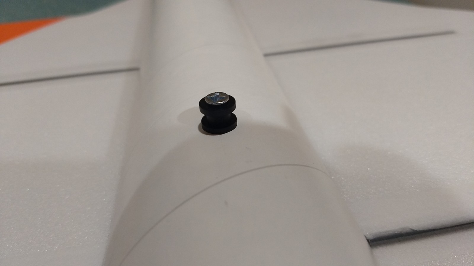
- Install the front and rear rail buttons.
-
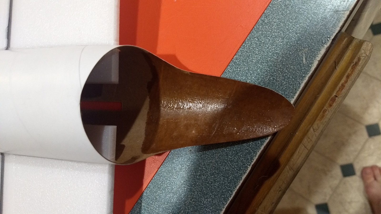
- Soak the rear of the body tube extension with CA glue to harden it from handling damage.
-
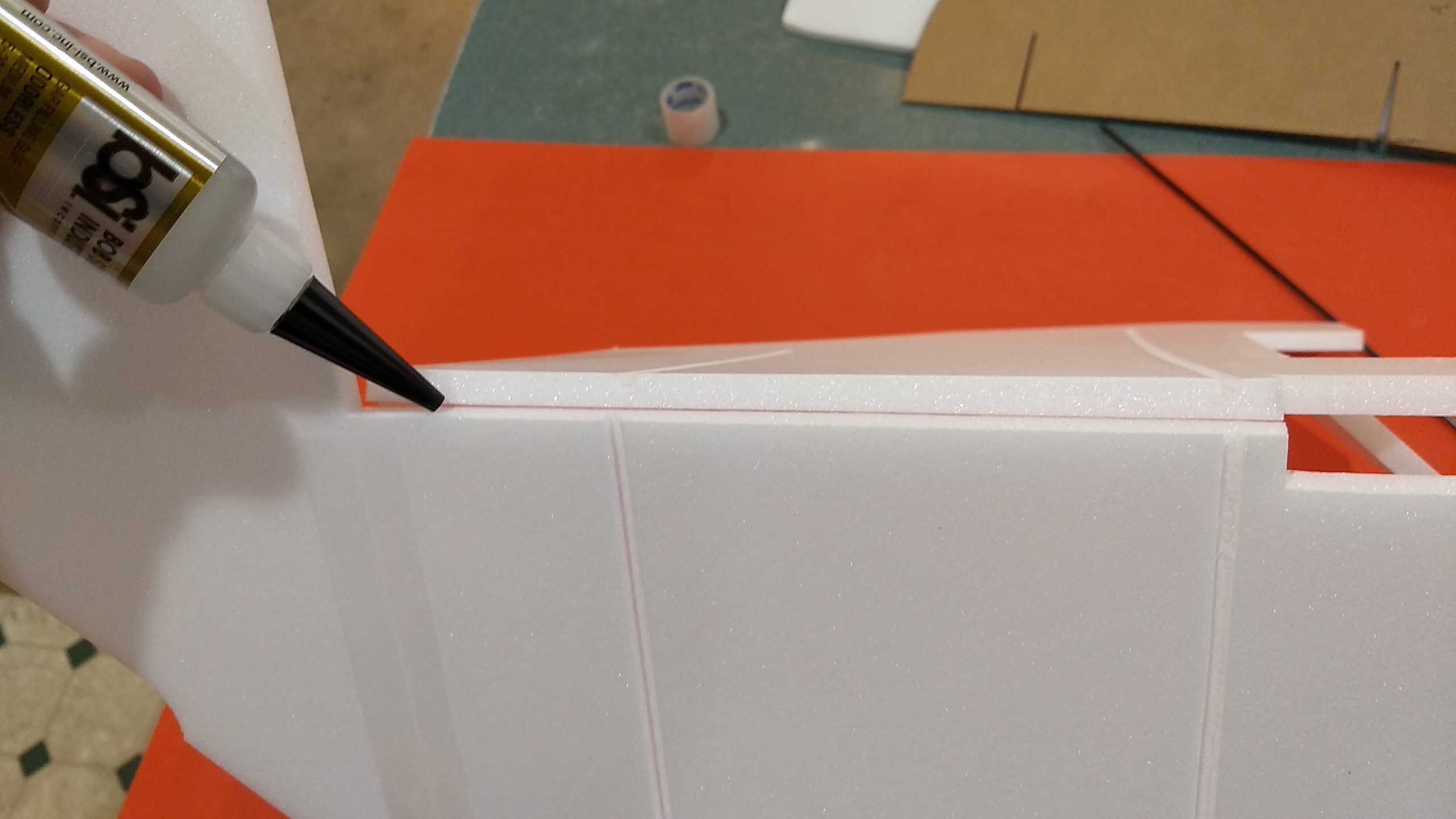
- Glue the taped wing joint and lay flat to dry
-
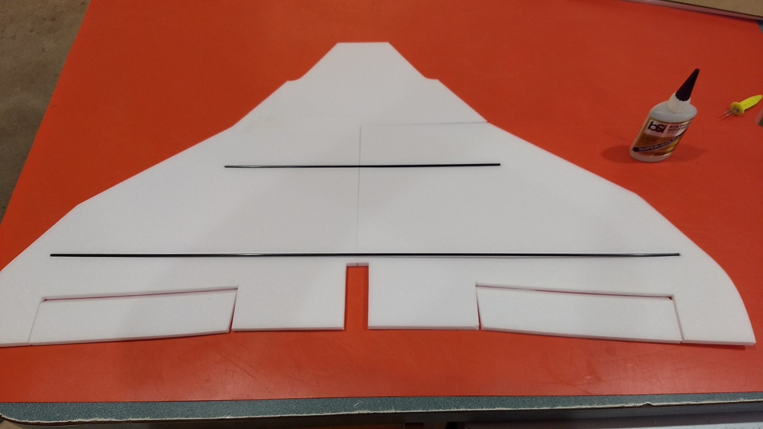
- Glue in the wing spar then tape over the spar and center joint on the bottom.
-
- Tape over the other half of the front wing horizontal joint on the bottom.
-
- Glue the horizontal wing joint and lay flat to cure.
-
- Apply tape to the horizontal top wing joint if you wish.
-
- Test fit then glue the wing in the slot.
-

- Glue the stab in place.
-
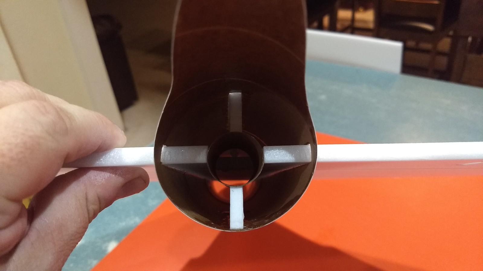
- Glue the motor tab onto the motor mount then test fit and install the motor mount so it is stops on the wing recess cutout.
-
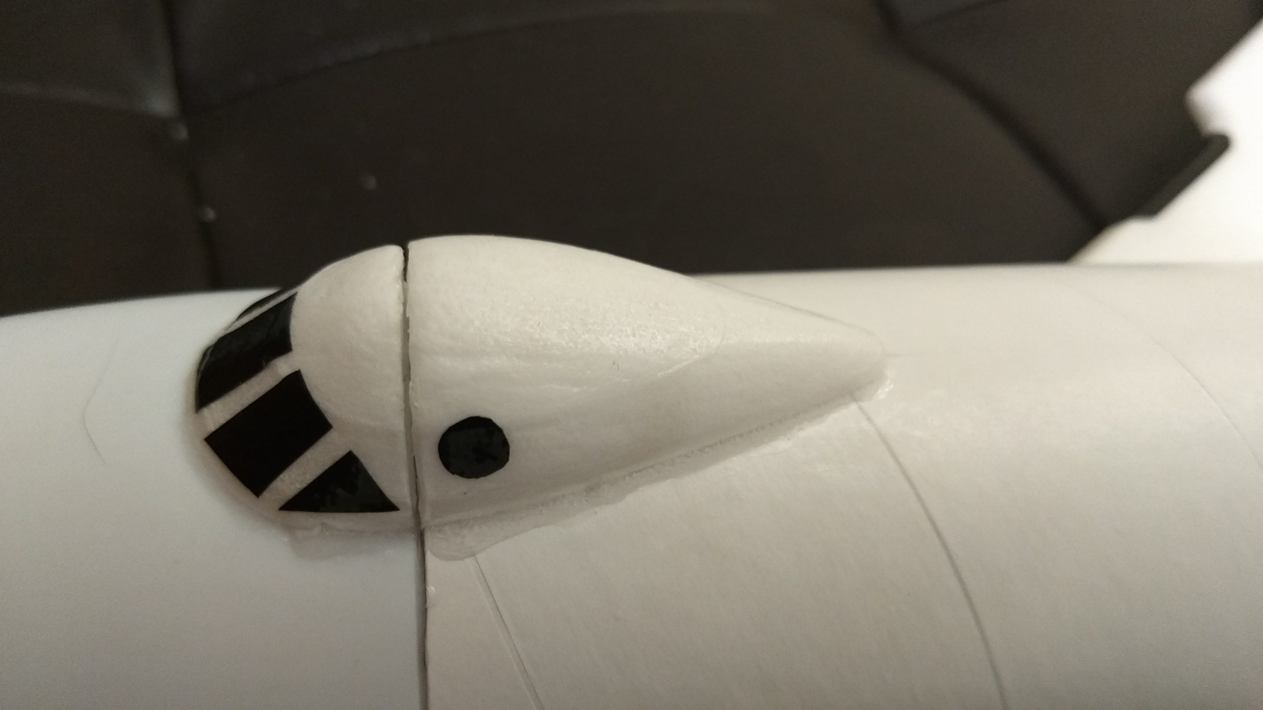
- cockpit shaped and installed, you can cut the cockpit to allow the cone to be removed or let the cockpit overhang the nose and glue it just to the body tube.
-
- Motor detail on the top of the wing on each side.
-
- Install the pushrod/horns in the pre-punched holes in the bottom of each surface, note the pushrod is closest to the body tube on each side so it angles inward slightly.
-

- install the servos onto each pushrod and glue in place keeping the outboard edge neutral with the wing. Cut a slot in the body tube and feed the servo wire forward to the front of the model, then tape the wire down to the wing and tape over the slot.
-
- Attach the receiver into the forward part of the body tube back far enough to clear the nose cone shoulder using velcro, the battery can be in the body or nose cone as needed for CG to avoid adding weight.
-
- Completed model
-
- Completed model top view