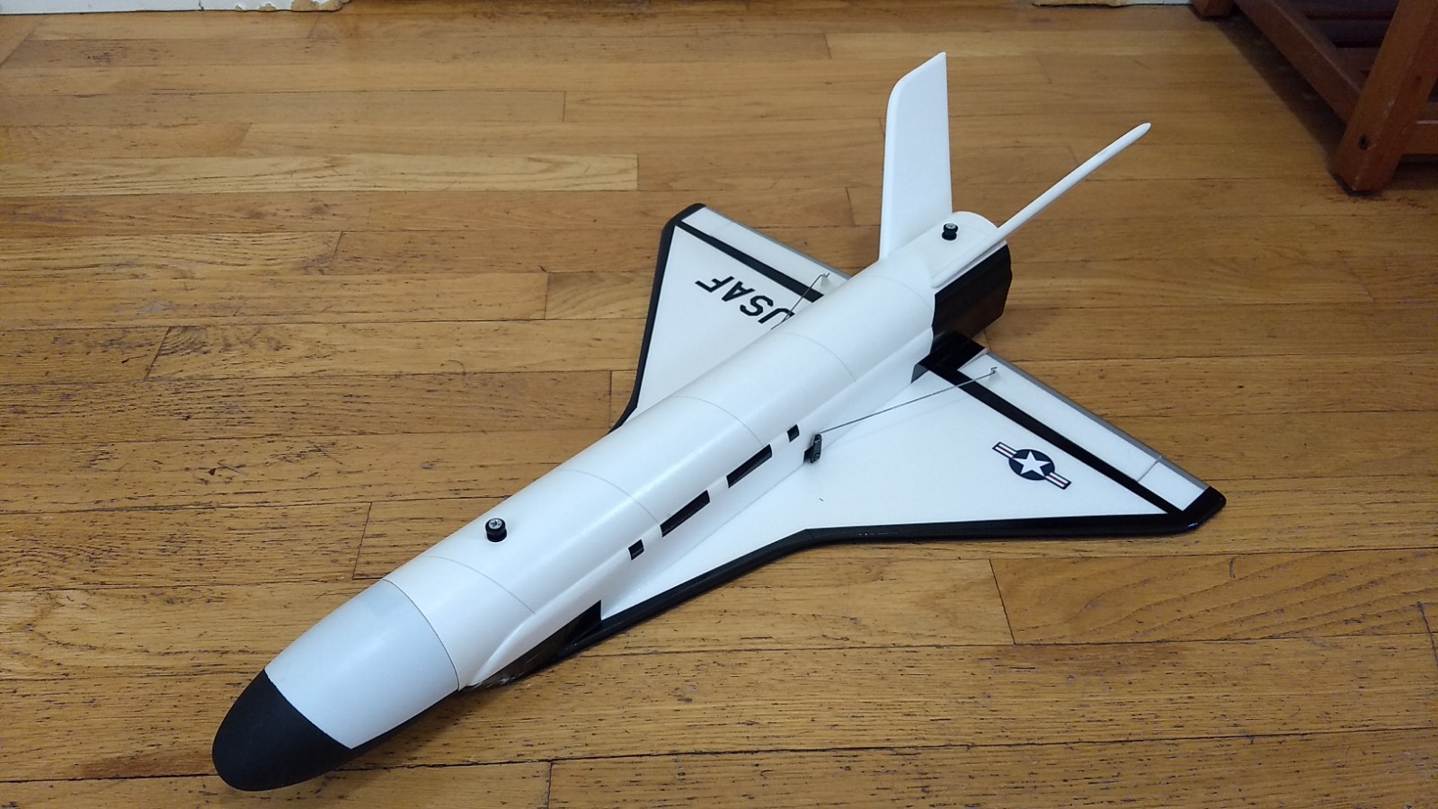
The OTV RC Rocket glider kit is based on the secretive X-37B Orbital Test Vehicle used by the US Air force on long duration secret missions and returns to earth to be re-flown. It comes with a plastic nose cone, 2.6″ white tubing for the body, and 6mm depron wing and tail surfaces and 3mm side plates and USAF decal for the wing. Body tube is pre-slotted for the V tail and rail button holes are pre-punched. Elevons are pre-hinged and spar is pre-installed. Construction and radio install is very simple. Please refer to the General information for all kits tab above, then read these instructions completely before starting assembly. Excellent high quality cut vinyl decals are available separately HERE:
CG location for rocket flight: 9″ or 22.8 cm forward of the rear end of the body tube.
Welcome to the world of rocket boosted radio control gliders. This is not a model for a novice RC pilot, but anyone who is comfortable with RC flying of a medium speed model should be fine. Read through the instructions, look at the photos and be sure you understand the step before commiting to cutting or glue.
Identify all pieces, the kit should contain:
1 wing taped together
1 Nose Cone, Estes PNC-80BB
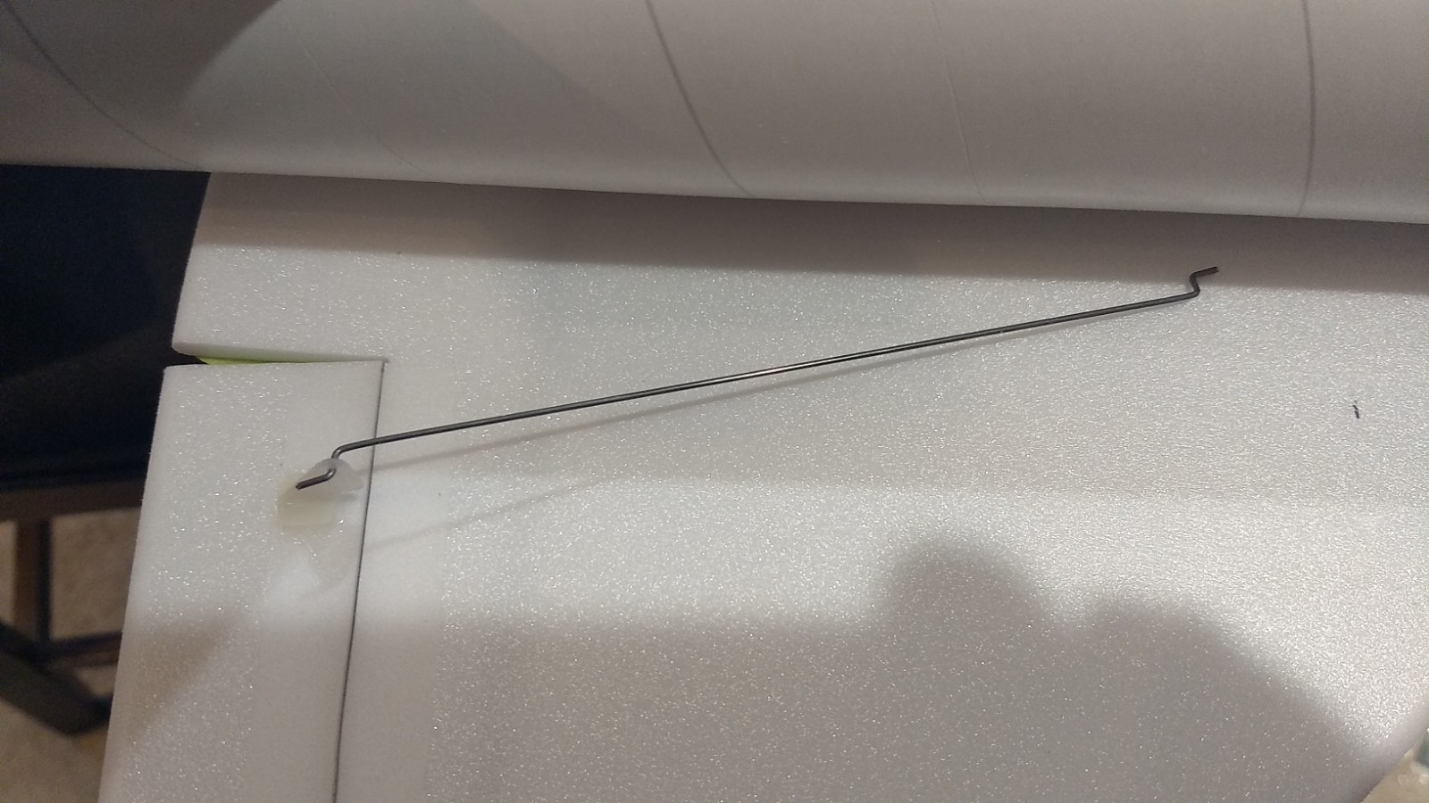
2 pushrods 2/horns
2 vertical stabilizers
1 18″ Estes/BMS lightweight BT-80 Body Tube
24mm Motor mount
1 13/16″ x 2.75″ strip to center the motor tube.
Velcro(for battery and rx/bec attachment)
2 Rail buttons with t nuts/screws
2 3mm depron side plates
Thrust ring
Lead weight
Spare foam (for testing paint, glue, and sanding the edges to see how it behaves)
Notes before starting:
Foam safe CA+(Bob smith super gold + is good) is the only glue recommended for construction. You will also need foam safe accellerator to set the glue.
You may use 220-320 grit sandpaper and a sanding block to slightly round the edges of the foam if you prefer before gluing the wing and vertical stab in place. Do any sanding before assembly.
Assembly:
- Glue the taped wing joint and lay flat to set.
- Apply glue to the wing line on the bottom of the body tube, lay the body tube on the top of the wing and make sure the front and rear alignment lines are lined up with the center of the wing at the front and back. **Note the front of the wing will be approximately 1/8″ from the front of the tube.
- Test fit the vertical stabs into the slots in the body tube carefully. Gue the vertical fins into place. Apply a light filet to both sides of the vertical stabs on the inside and outside of the body tube. The actual angle isn’t critical you just want them approximately the same.
- Install the front and rear rail buttons at this time.
- Glue the 2.75″ long foam strip on one of the motor tube lines
- If you do not use a reloadable motor you can glue the included thrust ring into the front of the motor tube. You will friction fit the motor for flight with a small bit of masking tape to make sure it doesn’t fall out, the reloadable motor will stop on the rear closure and you don’t need the thrust ring in that case.
- Test fit the motor mount into the body tube. Make sure it fits, or sand the foam tab lightly. Glue the motor tube in place flush with the vertical stab tabs at the rear, it will be inset about half an inch.
- I sanded the top edge of each side plate to a rounded taper to blend into the body tube. Make a left and right version.
- Apply CA+ to each of the control horns and press them in place in the top of each control surface into the pre-made holes. Note the pushrods will angle inward toward the body tube, there is a left and right.
- Apply glue to the prongs on the bottom of the wing to lock the horns in place.
The basic construction is now complete.
Radio Installation
Note: Your radio needs to be configured for Delta mixing, this means that the servo arms will move the same direction during elevator stick movement and opposite for aileron stick movement. Connect your servos to the receiver one in the aileron connection and one on the elevator connection and apply power. Use a servo arm at least 9/16” long and with holes small enough that there won’t be slop with the pushrod wire when installed. I use the hole furthest out on the servo arm, to maximize movement. On some servos there are a long two-ended servo arm, you can trim off one end if needed to get sufficient length. Zero out any trim settings on the transmitter. The model once the motor has burned out is nose heavy and flying wings lose pitch authority when nose heavy so you want as much up elevator travel for trim/flare as possible.
- Connect a servo to each pushrod. If the pushrod is too tight, you can use twist an X-Acto knife in the servo arm hole to make it larger, but be careful and do not make it too large. Once connected, tape each servo in place so that the control surfaces are centered. Look at the model from the rear. Moving the transmitter stick back(up elevator) should move both elevons up. Moving the transmitter stick to the right should move the right elevon up and the left elevon down. If you can’t get the servo reversing to give you the right polarity try swapping aileron/elevator inputs to the receiver or turning the servos over and swapping the servo arms to the other side of the output shaft. If that is correct, continue.
- The servos may be attached to the model using double back servo mounting tape(not included) or by directly gluing the servo to the wing with foam safe CA+. Double back servo tape can loosen over time and with exposure to heat, I prefer to glue the servo in place.
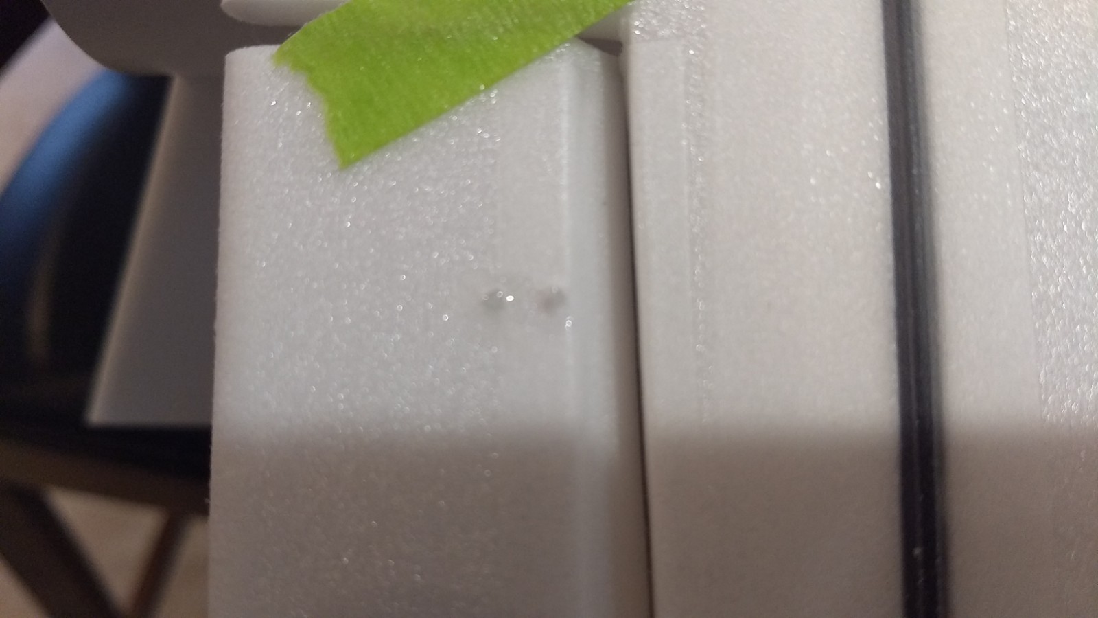
- Mark where the servo will be when the control surface is neutral and cut a notch into the body tube so that the servo is inset slightly. Repeat on the other side. Attach a servo extension to each servo, route the wire into the notches on each side and out the front and re-connect the servo to the receiver. I inset them as far as I could, this left just a little bit that I needed to trim out of the side plates when mounting them.
- With the radio still on, put a moderate amount of glue on the servo, being careful not to get any near the output shaft, and set it in place on the wing in the pocket you just cut, keeping the control surface centered. Do the same to the other side. Make sure the glue is set before continuing. If you need to adjust the pushrod by bending the angle at the control arm so the servo is not angled, simply do so with a needle nose pliers before gluing the servo in place.
- Make sure the control surfaces are centered, use trims if needed. Now measure the control surface movement. Full elevator movement should be 5/8” in each direction, aileron movement should be 3/16″-1/4″ in each direction. (My model was extremely roll sensitive, you may want to use exponential to reduce throw around center to avoid overcontrolling or reducing throw after the first trim flights if needed) Since the model will be nose heavy, extra elevon movement helps to give sufficient authority during glide.
- If you have a flap/elevator mix you can program up elevator to a switch setting. The model needs approximately 1/4″ to 3/8″ of up trim for glide. If you can’t set the up elevator trim to a switch on your radio you’ll have to manually put in boost and glide trim which is hard to do while flying the model. You can also use flight modes to set different launch and glide elevator trim settings and control those via a switch.
- Test fit the two side plates. You will need to cut a notch in each one to clear the servo and pushrod arm for free movement. The size of the notch will depend on your servos and how far in you recessed them.
- Glue the side plate to the model on each side. The front will hang down over the front of the wing and be even with the front of the body tube. When the side plates are dry, apply glue to the lower front part of the side plate and wrap it around the bottom of the model and form it to shape against the wing and hold till it is set. Once set trim the extra foam and sand it to a pleasing shape.
- Use the included Velcro to attach the receiver inside the nose cone. This allows you to be able to remove and replace the receiver if needed for repairs or for removing the servo wires.
- I attached the battery inside the nose cone as far in as I could reach to avoid needing nose weight.
- I can only recommend testors/model master enamel spray at this time, others I’ve tried damage the foam surface. I recommend flat colors as they dry faster and the surface imperfections of foam aren’t as noticable. I left the body tube and top of the wing bare(no paint to save weight) and just masked off and painted the sides/bottom of the wing and nose cone flat black. Balance the model after painting as it adds weight. Use the pictures as a rough guide for painting, or look at photos of the X-37B for more detail if desired.
- Once you apply the wing markings, after application use a hair dryer on hot to warm the markings and them push them down into the foam surface with your finger. The will really conform and stick down well.
- Insert your heaviest loaded rocket motor into the motor mount
- Support the model at the balance point indicated for boost. I use two pencils with the eraser pointed up and held in place with a small hand vice. Place the model upside down on the pencil erasers on the balance point indicated above. Use pieces of the included lead weight as far forward into the tip of the nose to balance it, or in the tail as needed. Glue the lead weight in place so it does not shift during flight. Do not try to fly the model too nose or tail heavy. Remember, a nose heavy model flies poorly, a tail heavy model flies once
- Re-install the receiver and battery
Flying: See the General Instruction link at the top for flying instructions. Be ready on the first few flights to keep the model straight till you have the trims set perfectly for boost and glide.
-
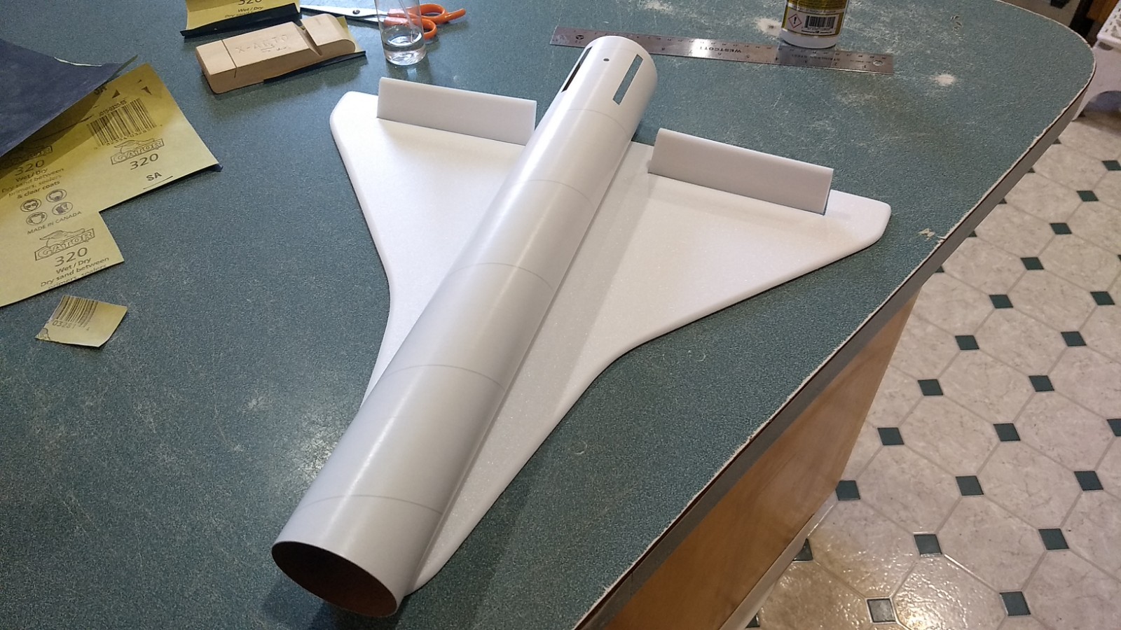
- After gluing the wing at the taped joint, glue the body tube to the wing.
-
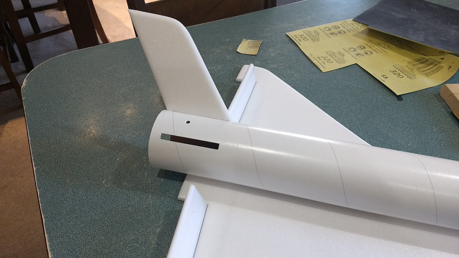
- test fit then glue a vertical stab in place.
-
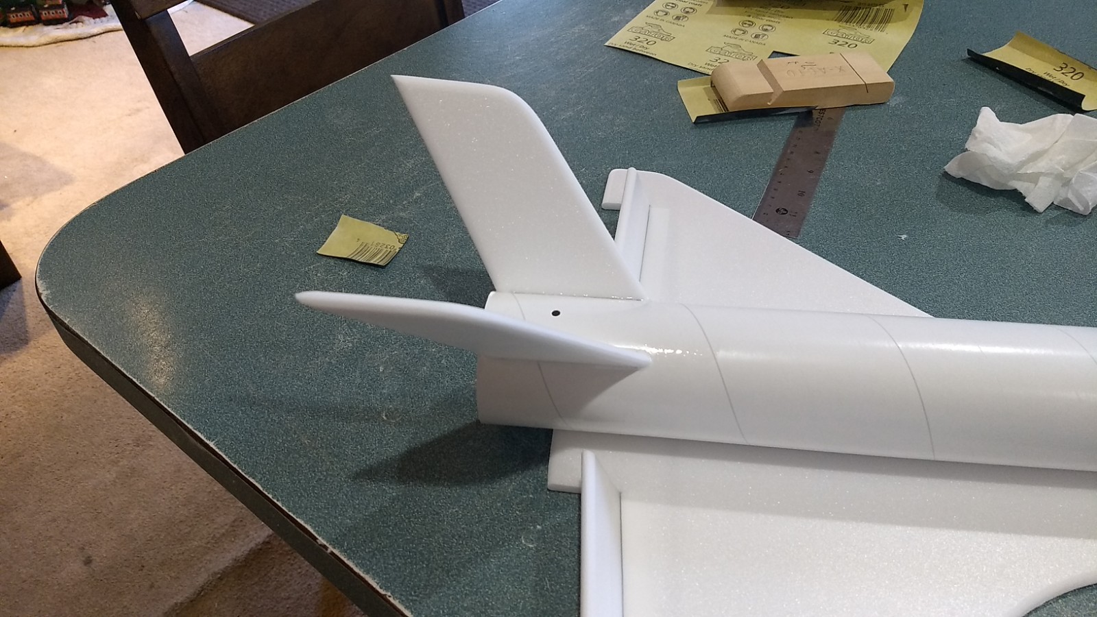
- repeat for the other stab.
-
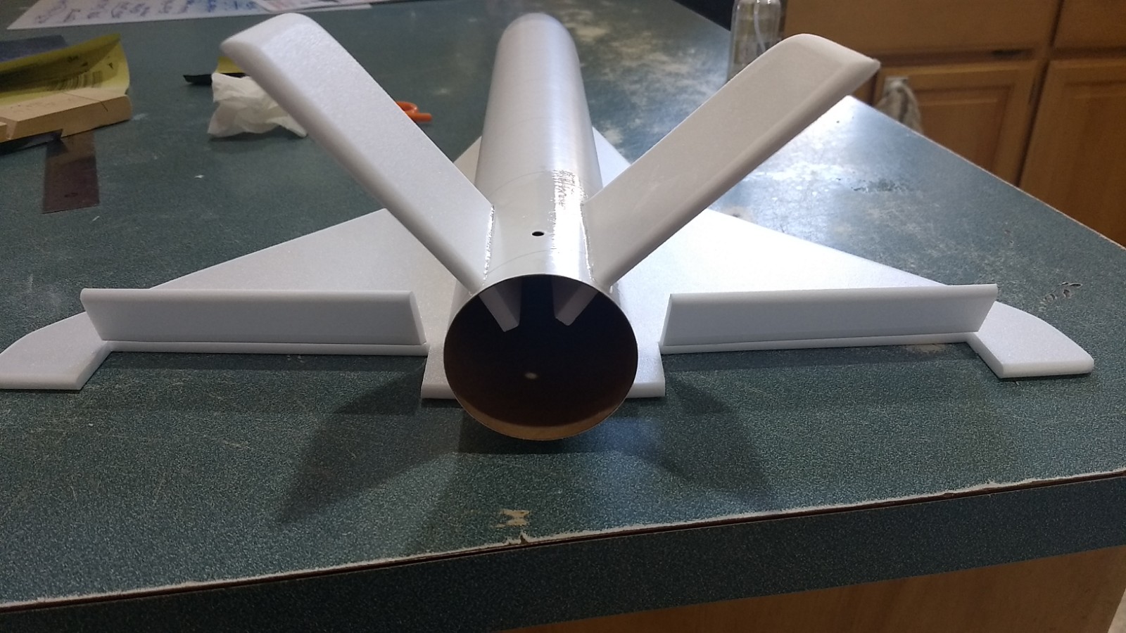
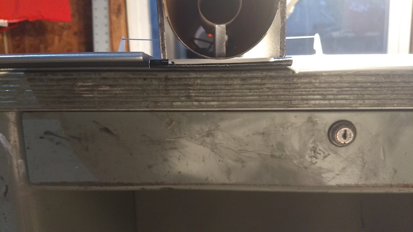
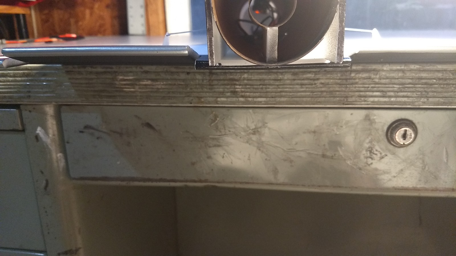
- Stabs installed showing equal angle on each side.
-
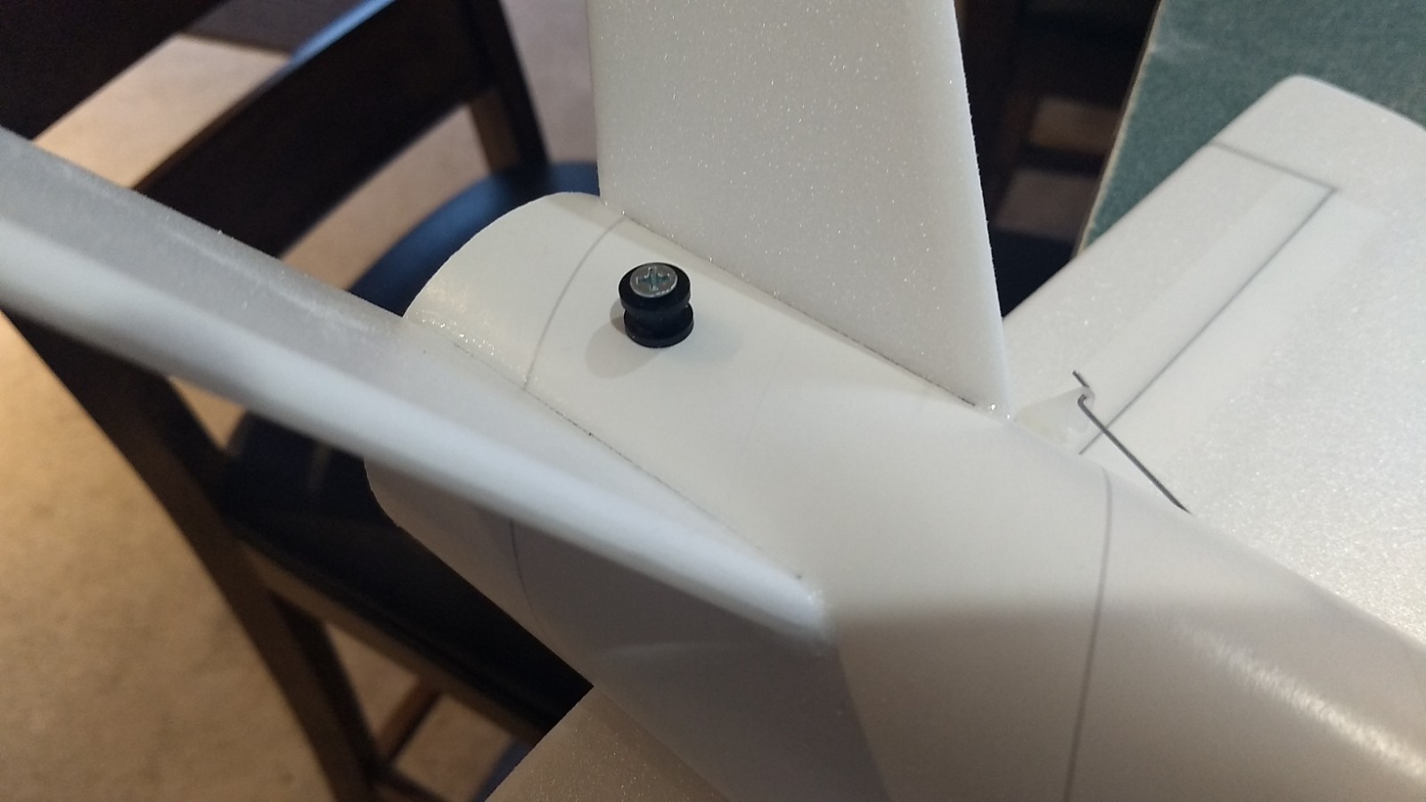
- Install the rear rail button
-
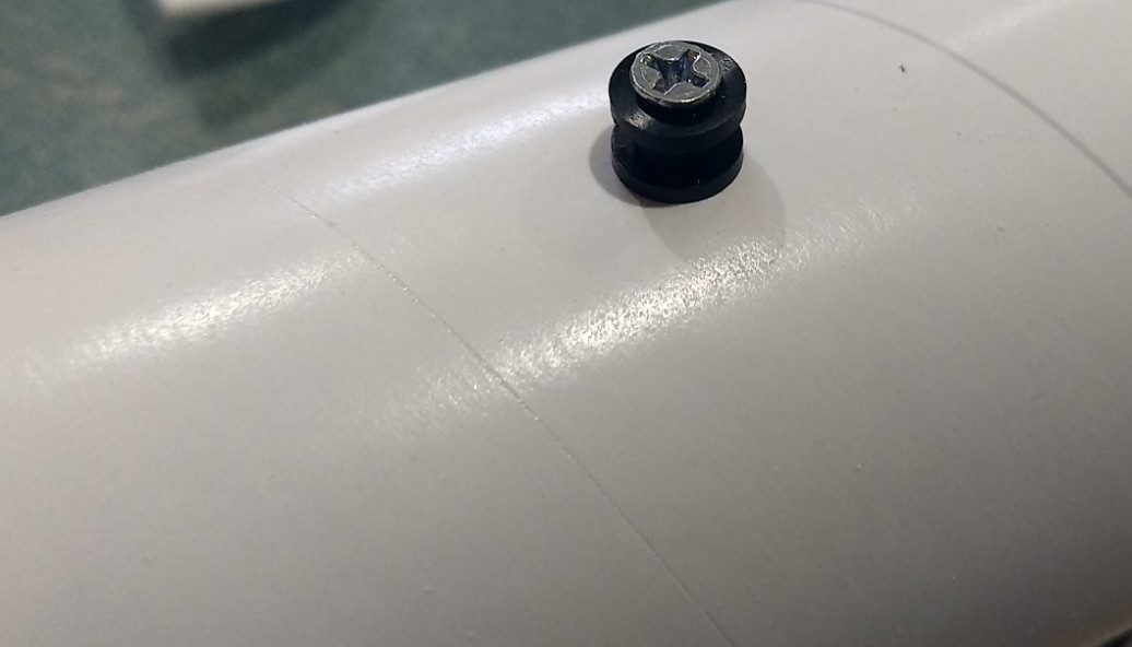
- Install the front and rear rail buttons
-

- Glue the motor centering strip to the motor tube on one of the lines.
-
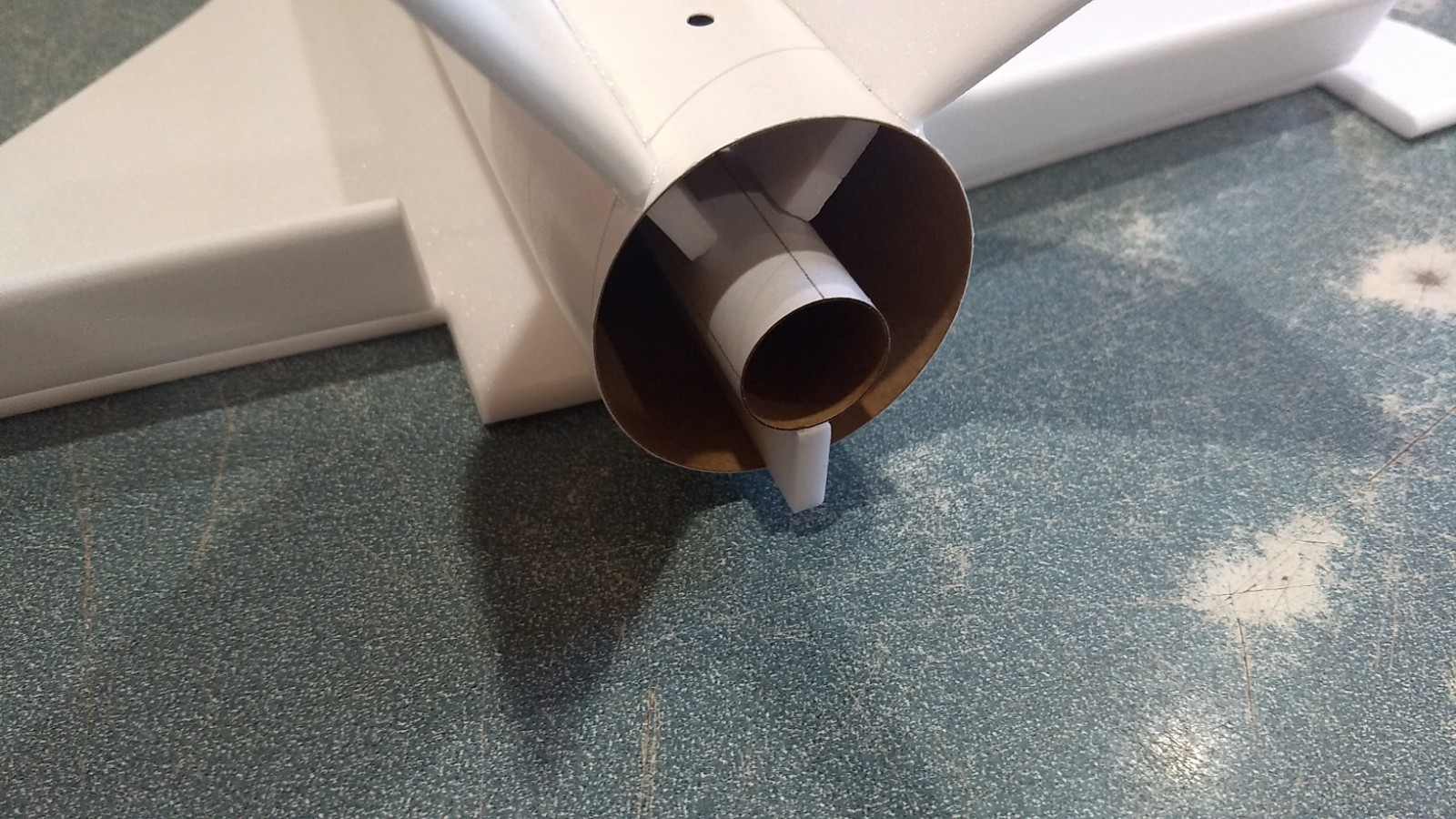
- Test fit the motor tube into the model.
-
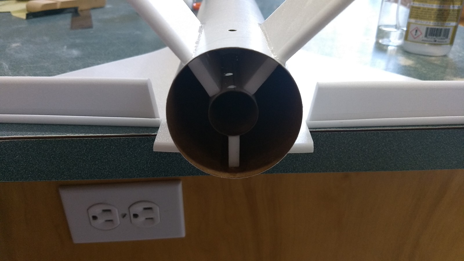
- Inset the motor tube even with the rear of the fin tabs and then glue in place.
-
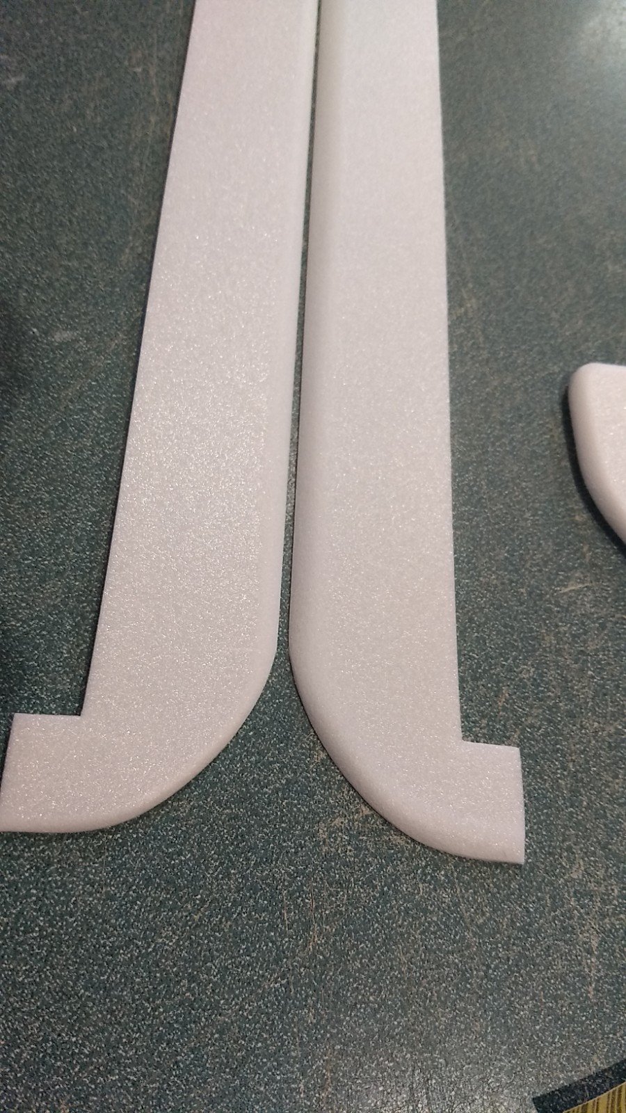
- Sand the top of each side plate round, make a left and right.
-
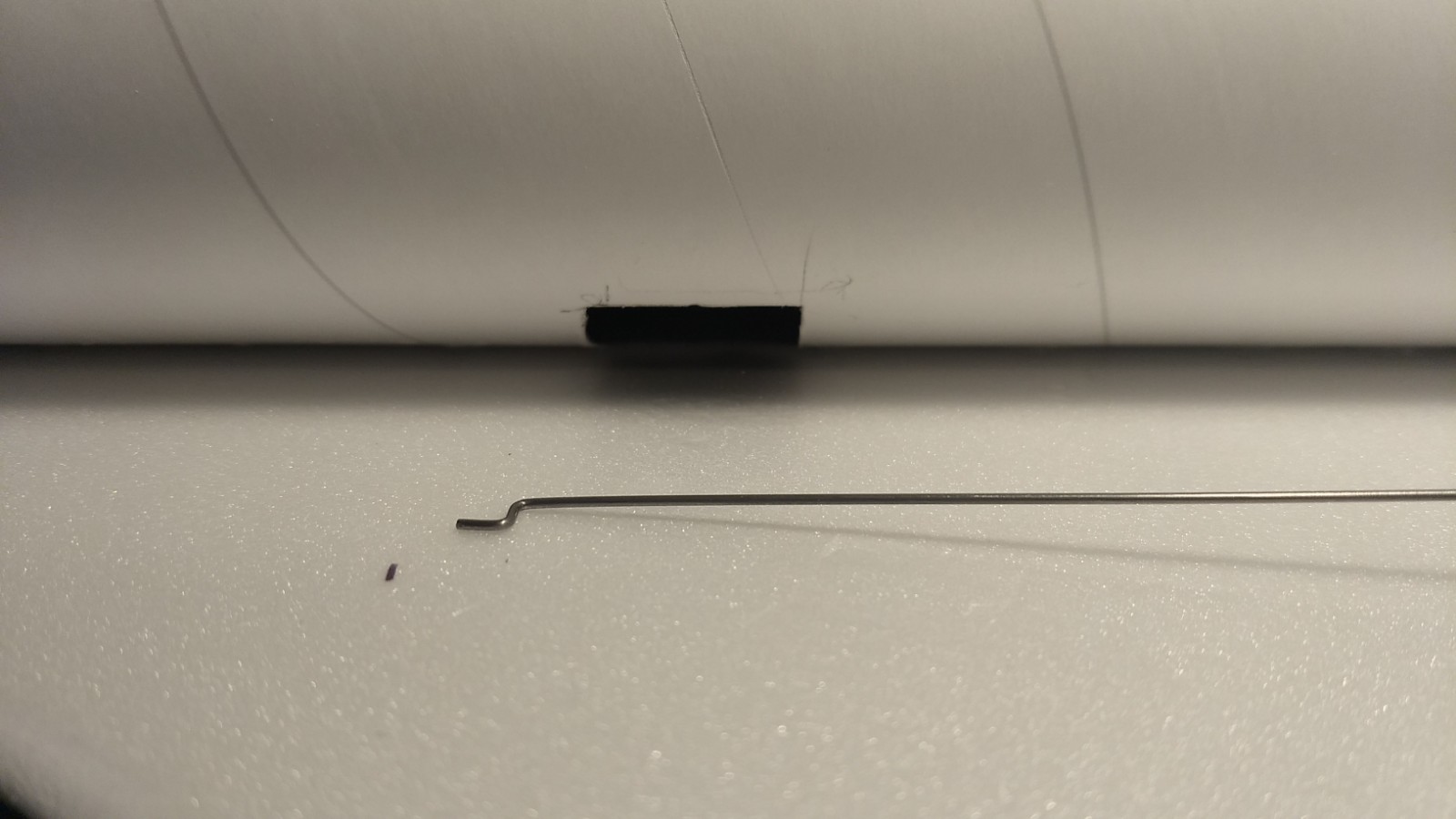
- Glue the control horn into the top of each control surface, note the pushrod will angle inward toward the model.
-
- Apply glue on the prongs on the bottom of each horn.
-
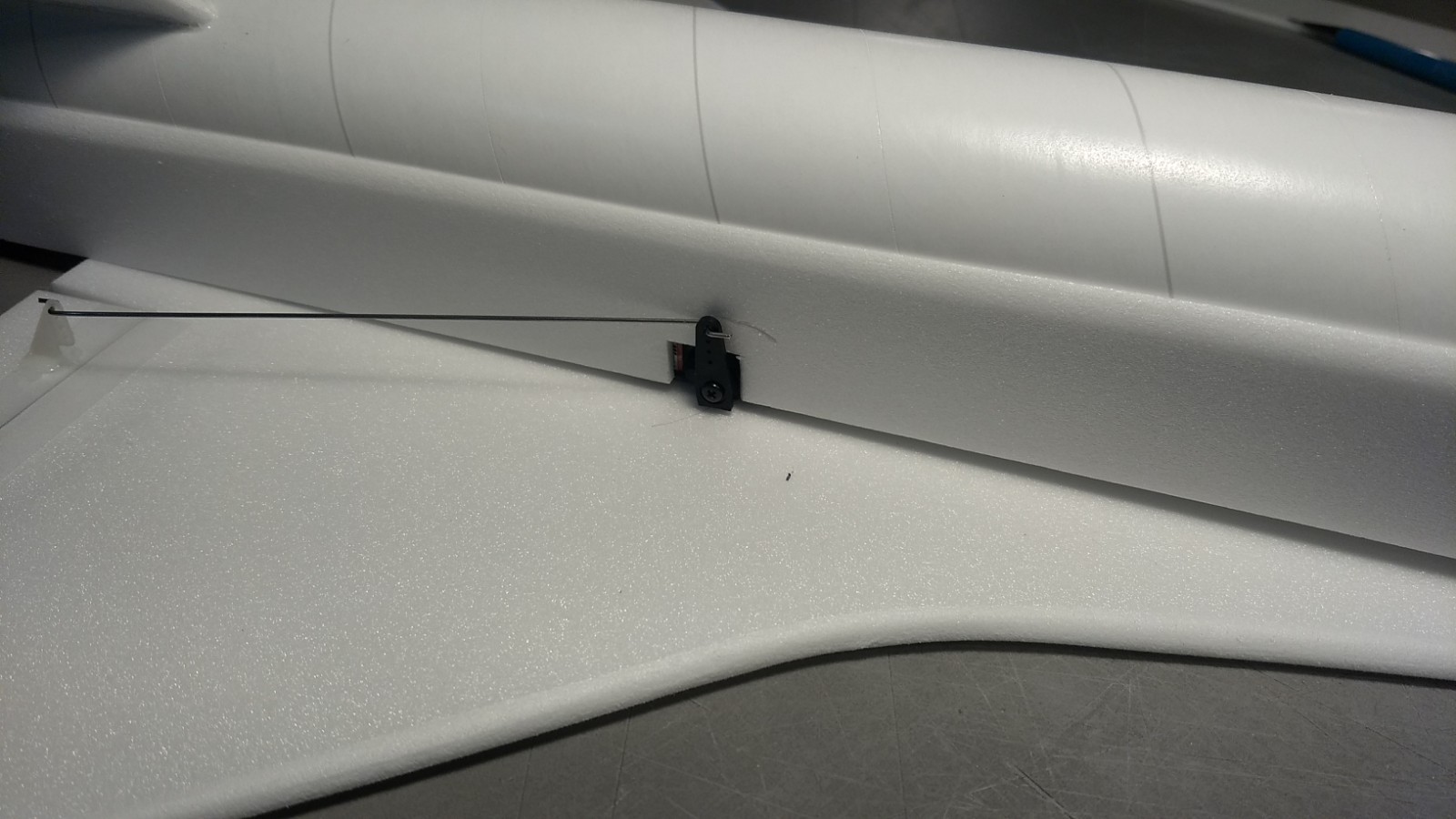
- Measure then cut a pocket for each servo on each side.
-
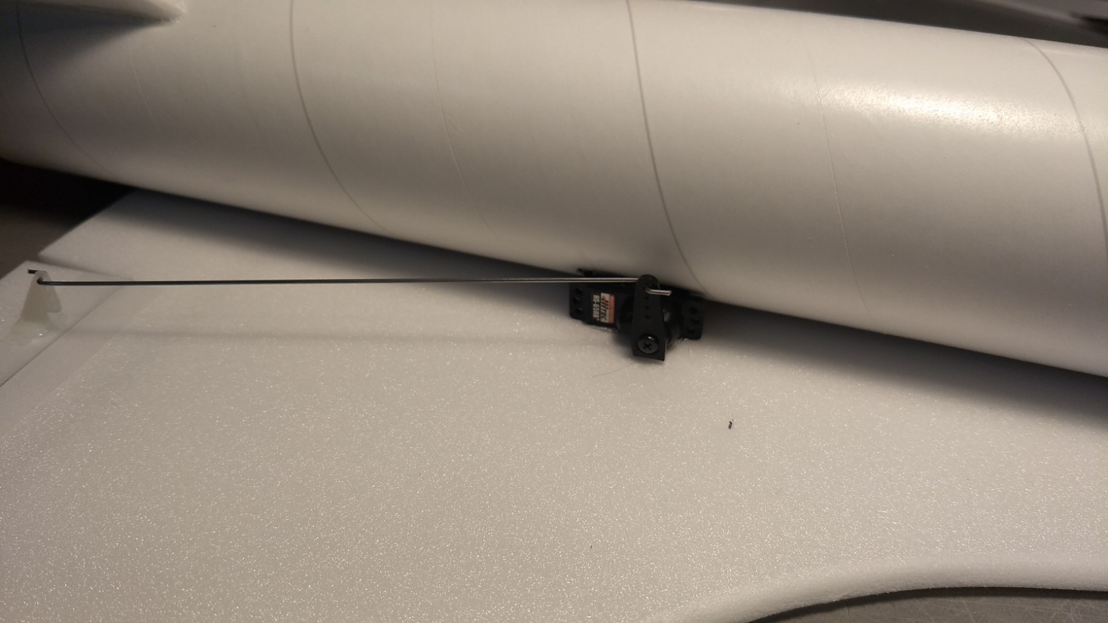
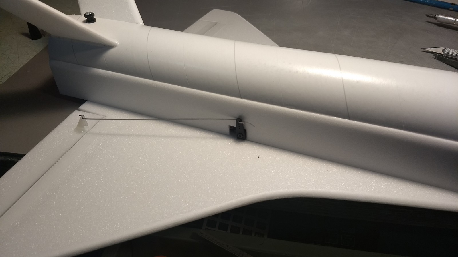
- Test fit then glue a servo into the pocket against the wing keeping the control surface neutral.
-
- Taper the top of each side plate to blend it into the body tube then cut out each side plate to clear the servo arm and wire and then glue the side plate to the wing and fuselage, the front should be even with the front of the main body tube.
-
- Glue the side plates on, then wrap and glue the side plates around the front of the wing and bottom of the tube at the front. Trim and sand round when dry.
-

- Receiver and battery connected out the front of the body tube. Power up the radio and adjust control throws and glide/boost settings.
-
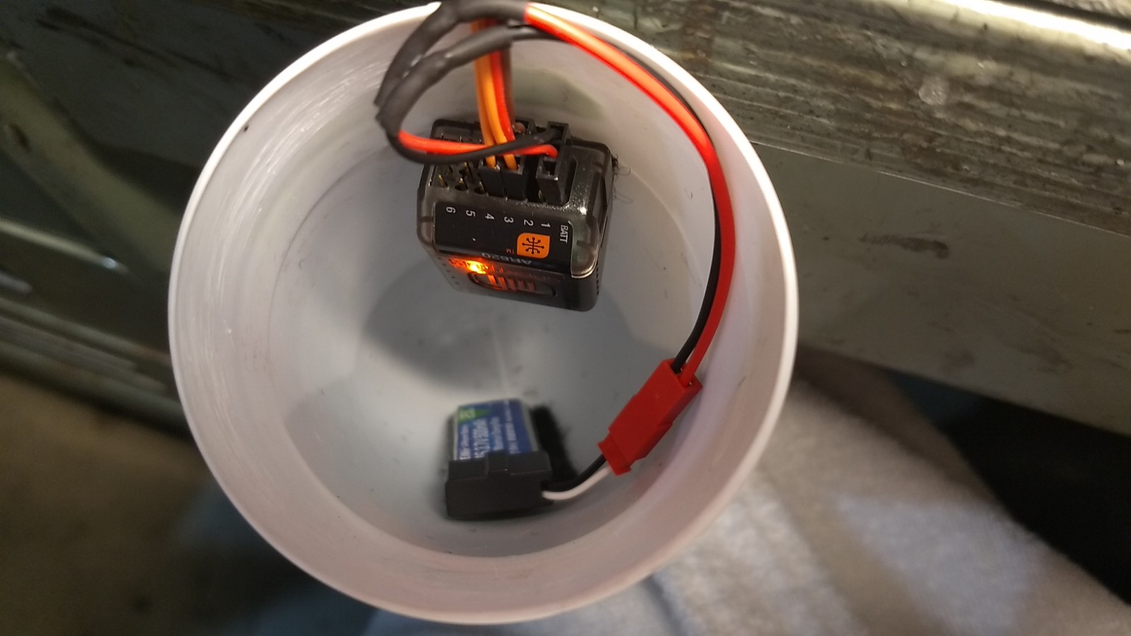
- Receiver and battery mounted as far forward into the nose cone as possible with velcro.
-
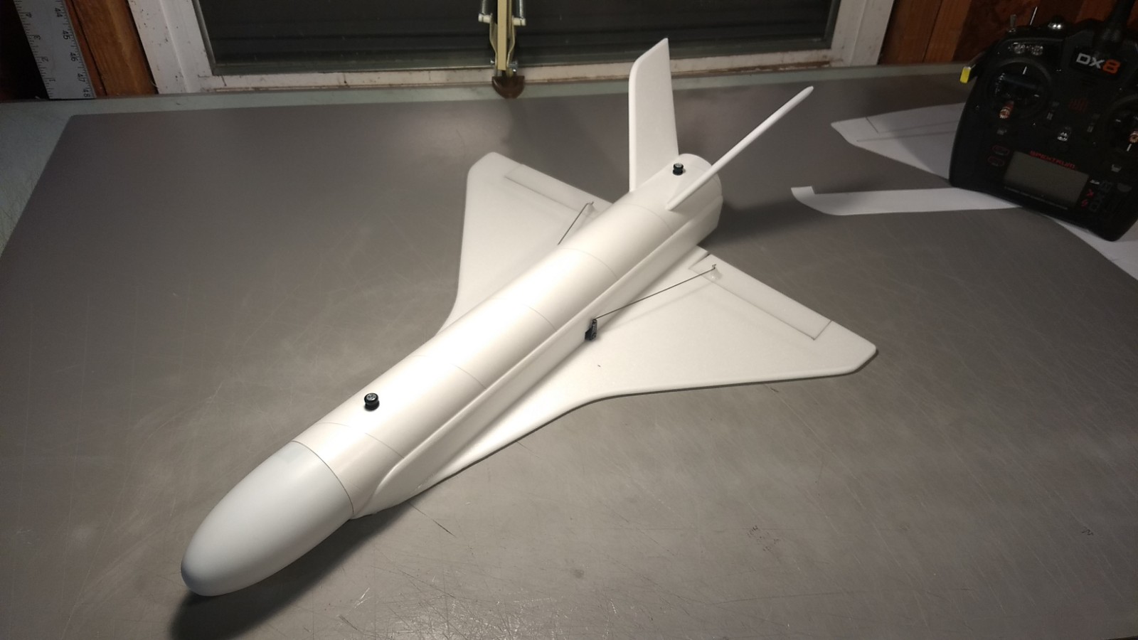
- Airframe complete.
-
- Completed model
-

- Top view
-

- Rear view.
-

- Up elevator
-

- down elevator
-
- Left aileron
-

- Right aileron
-
- Glide trim