
This kit is for the experienced flyer, as the heavier flight weight and small wing requires more finesse to avoid damage to the ramjet pods when landing. Length 42″, 2.6″ diameter, 14.25 oz rtf and has a 21″ wingspan. It is approximately the same size as the madcow 2.6″ kit but approximately 1/3 of the rtf weight. High quality cut vinyl decals are available from Stickershock23 HERE
Please refer to the general instructions link above then read the instructions completely before starting assembly. You will need a receiver, two 10 gram type good quality servos, 500mah 1s battery, 2 24-36″ long receiver extension wires, and a radio capable of elevon mixing and assigning elevator trim settings to a switch. The assembly photos are for general reference but may not include every step in the manual.
CG location for rocket flight 9 1/8″ forward from the TE of the wing, CG to be checked with battery and rocket motor installed ready to fly.
Welcome to the world of rocket boosted radio control gliders. This is not a model for a novice RC pilot, but anyone who is comfortable with RC flying of a medium speed aileron controlled fixed wing model should be fine. Read through the instructions, look at the photos and be sure you understand the step before commiting to cutting or glue.
Instructions:
Identify all pieces, the kit should contain:
1 wing taped together
2 pushrods
1 Vertical Stabilizer
1 horizontal stab assembly.
2 long angle cut Foam wing reinforcing strips
2 medium angle cut Foam horizontal tail reinforcing strips
2 short angle cut foam motor mount reinforcing strips
2 Body Tubes
1 coupler
2 foam ramjet intake disks
2 paper cone patterns
2 ramjet standoffs
2 ramjet tubes
4 2″ long carbon ramjet support rods
3 long 3/8″ wide foam strips for the conduits.
Motor mount
Thrust ring
Battery adapter wires
Velcro(for battery and rx/bec attachment)
2 Rail buttons/t-nuts
Lead weight
Spare depron
Notes before starting:
Reference to CA+ means foam safe CA+, this is the only glue to use on this model, normal CA+ will melt the foam! Normally you need to use accelerator to get the CA to set on the foam since there is nothing for it to soak into and activate.
I prefer to bevel the leading and trailing edges of the flying surfaces instead of sanding. I’ve found the best way is to use a sharp exacto and a thin straight edge and simply cut a 1/16″ bevel on the top and bottom of each surface corner. Do this before assembly.
Weight is critical and the model is designed for the thrust and flight loads. Weight in the rear end is bad and will require additional weight in the front of the model. Do not use epoxy, it is not necessary and adds weight. I do not recommend painting the model other than the nose cone as weight is critical.
Assembly:
- Unfold the wing and glue the tape joint using CA+ and accelerator, make sure it is flat
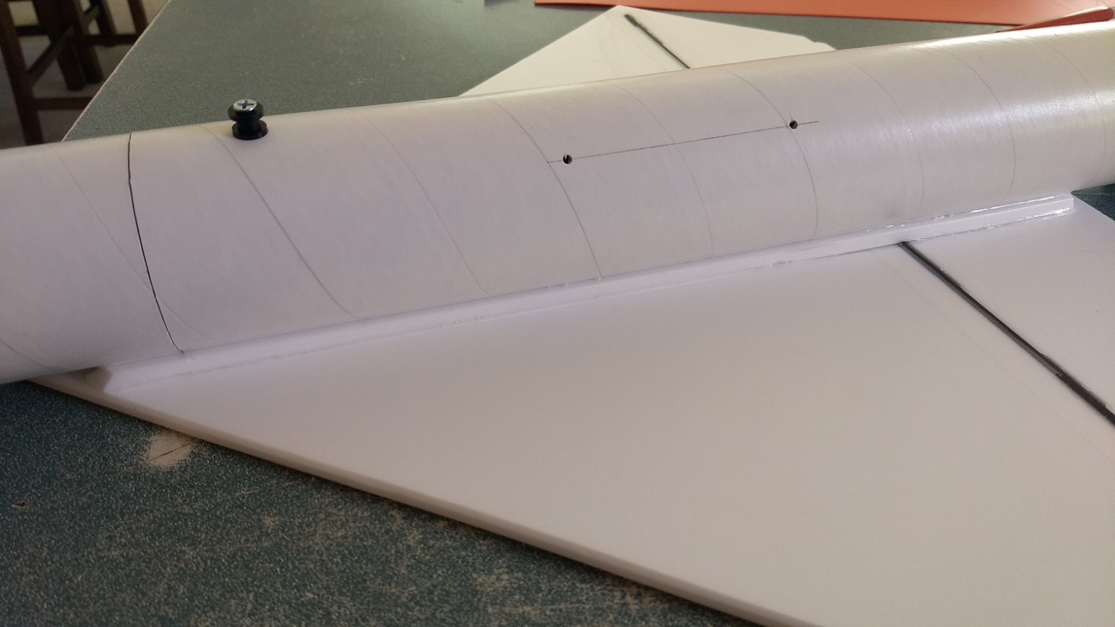
- Install the rail buttons into the rear tube with the larger pre-punched holes at this time. The T nut goes inside the tube and through the hole, then slide a plastic washer, then collar, then another washer and finally the screw. Don’t tighten down too hard as it can distort the button and cause binding on the rail.
- Join the front and rear body tubes using the coupler keeping the arrow marks aligned on the two tubes to make sure the hand cut joint is perfectly aligned and to avoid gaps.
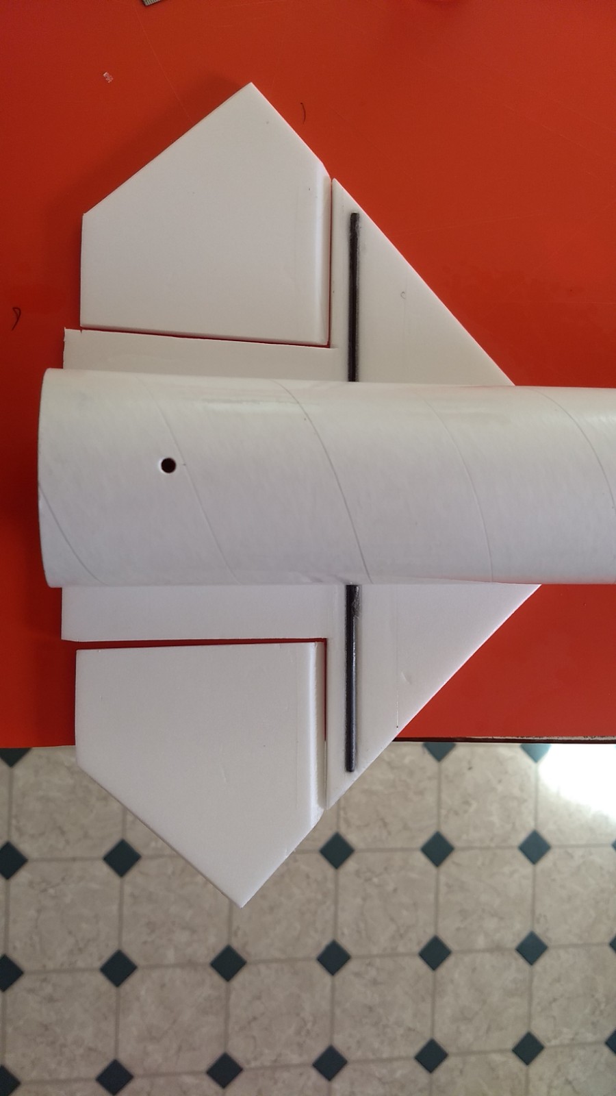
- Glue the horizontal stab assembly to the top of the rear body tube with the rear of the stab flush with the end of the tube. The spar should be pointing down. Use the alignment line on the tube to make sure it is straight. Tape the front and rear in place and Flip the model over and hold it in place while the glue sets. Make sure the tube is not rolled to one side or the other and the rail buttons stay vertical.
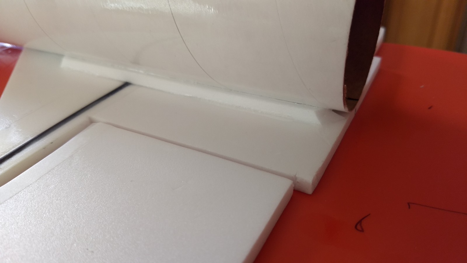
- Glue the two medium reinforcing strips on either side of the horizontal stab/body tube joint and add a small CA fillet. This provides extra strength for the joint. Don’t push the strips in too hard.
- Using CA+ foam safe glue, glue the wing to the body tube. The spar should be pointing down. Use the pencil marks on the body tube as a guide to keep it straight and at the correct position. Make sure the rear of the wing is 1.5″ forward of the front of the horizontal stabilizer assembly using the pre-marked lines. Tape the front and rear in place then flip the model over and on a flat surface to make sure the wing stays parallel to the horizontal stab, hold in place while the glue sets with hand pressure.
- Apply CA+ foam safe glue to one of the long reinforcing strips and glue one on each side of the wing/body tube joint. This piece is there to give more gluing surface to the wing/body tube. Don’t push in too hard on these strips it can cause the body tube to rotate slightly. Once they are in place put a fillet of CA+ on both the wing and body tube joints.
- If you are using single use motors glue the motor thrust ring into the end of the motor tube. If you are using reloads, you don’t need the thrust ring, the rear closure will prevent the motor from moving forward and I just use a small piece of masking tape to keep the motor from falling out after burnout.
- Glue the motor tube to the body tube at the rear even with the end. Use the alignment line inside the body tube. Make sure the motor tube is aligned straight with the body tube. Look from the front of the body tube and make sure the motor tube is not angled. There are no centering rings needed or desired because you may need to reach wiring or weight at the rear of the model.
- Glue the two short reinforcing strips on either side of the motor tube and add a fillet of CA+ to help support the motor tube.
- Glue a foam disk into the front of the ramjet, the front is the end closest to the two pre-punched holes.
- Cut out the two paper cones. Roll the paper over a table top to curve it and then glue the tab to make a cone. I used contact cement on the tab. Glue a cone to the front of each ramjet, then reinforce the outside of the cone with foam safe CA glue to harden it. I did a few layers letting it cure inbetween.
- Insert the 1/8″ short carbon rods into each ramjet standoff so that an equal amount is sticking out of each side.
- Glue a standoff to each ramjet tube using the holes provided, try to keep the standoff perpendicular to the tube. If there is any misalginment of the holes and rods simply wiggle them a bit as you insert them. Apply a fillet of glue on each side of the standoff.
- Before the next step if you are using the stickershock decals it is much easier to apply them to the ramjets before attaching to the main body.
- Paint the ramjet intake as you wish using foam safe paint, acrylic is a good choice.
- Apply the large white wrap to the front of the tube centered around the ramjet standoff.
- Apply a thin narrow silver strip at the very front of the ramjet tube over the white section.
- Apply the silver wrap to the rear of ramjet tube, it will overlap the white about 1/4″.
- Glue each ramjet pod into the fuse using the holes provided. Apply a fillet of glue on each side of the ramjet standoff at the body tube joint. Again, if the holes/rods are misaligned slightly just wiggle or englarge the holes slightly till they will slide into place. The rods are there more for alignment than strength.
- Flip the model over and glue the vertical stab to the horizontal stab using the tab. Make sure it is 90 degrees to the stab, is straight and reinforce with a slight fillet on each side.
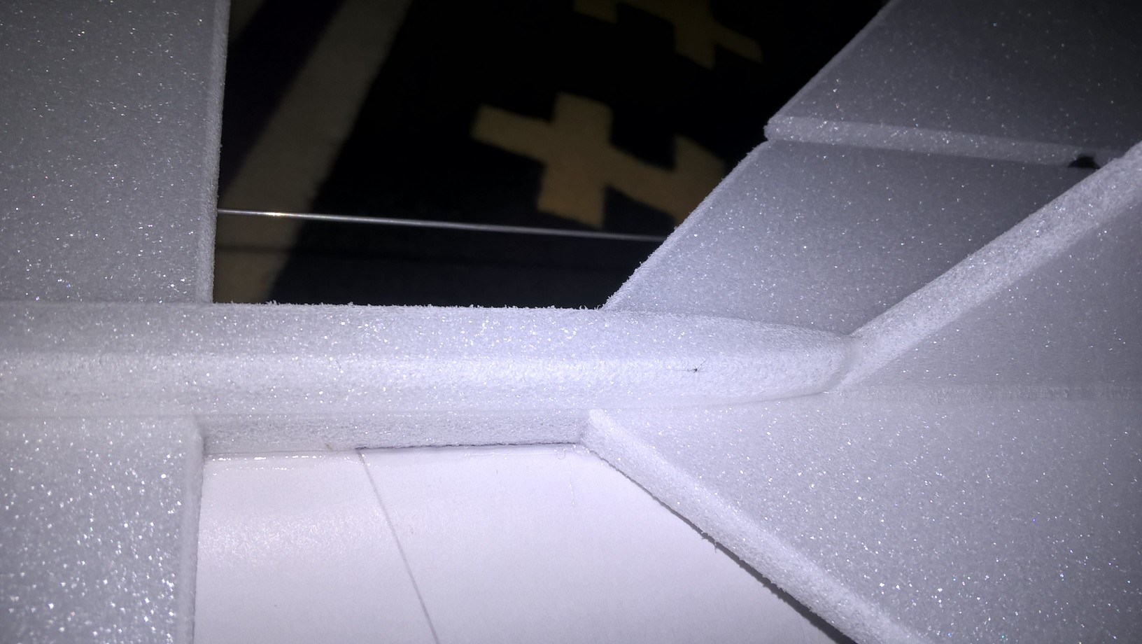
- Cut a strip of 3/8″ wide foam conduit to fit between the TE of the wing and the front of the stab. Glue it in place.
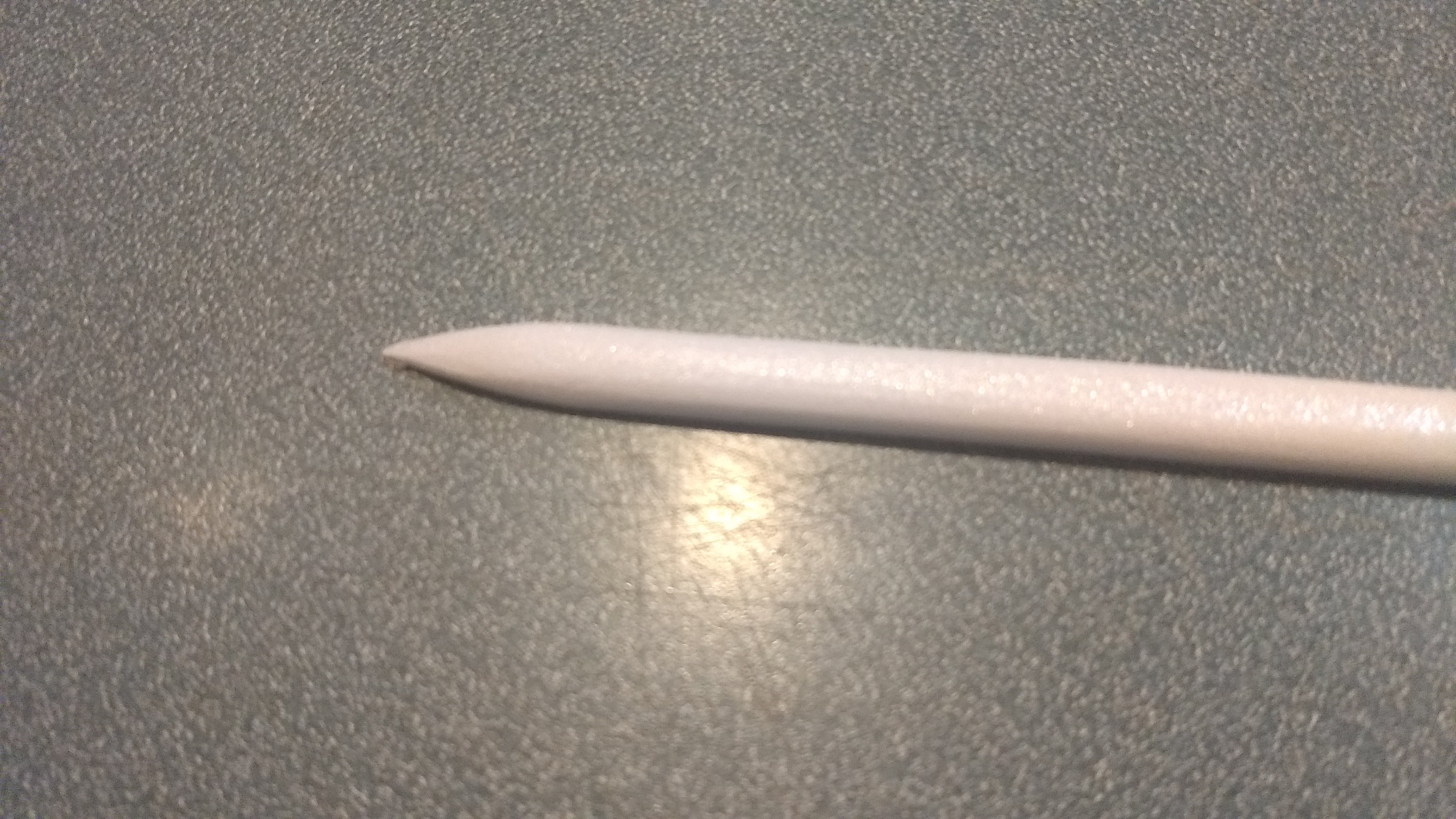
- Use the remaining strip of 3/8″ wide foam to go from the front of the the wing to the front of the body tube. You will need to sand/cut the front to a pointed shape.
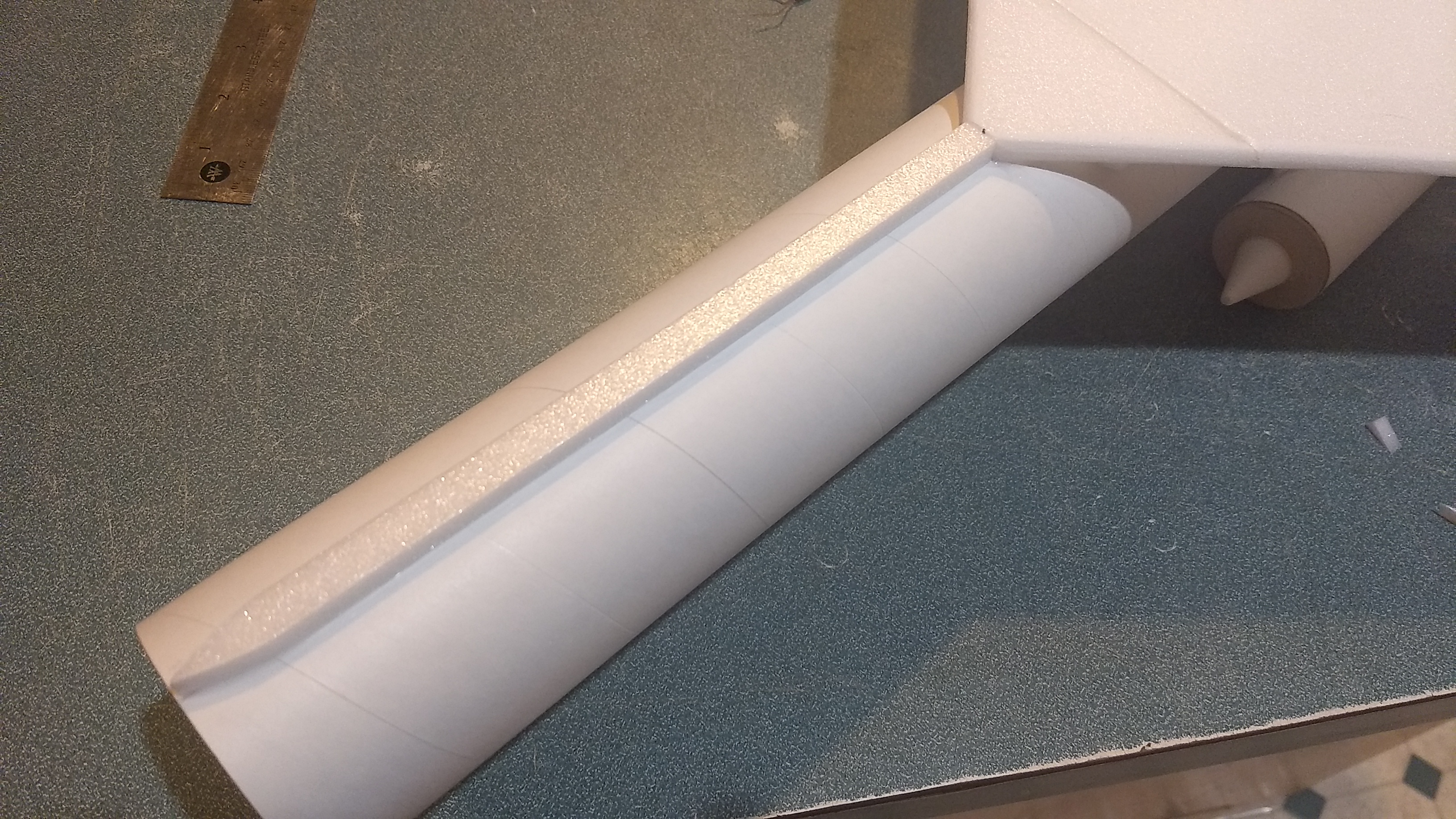
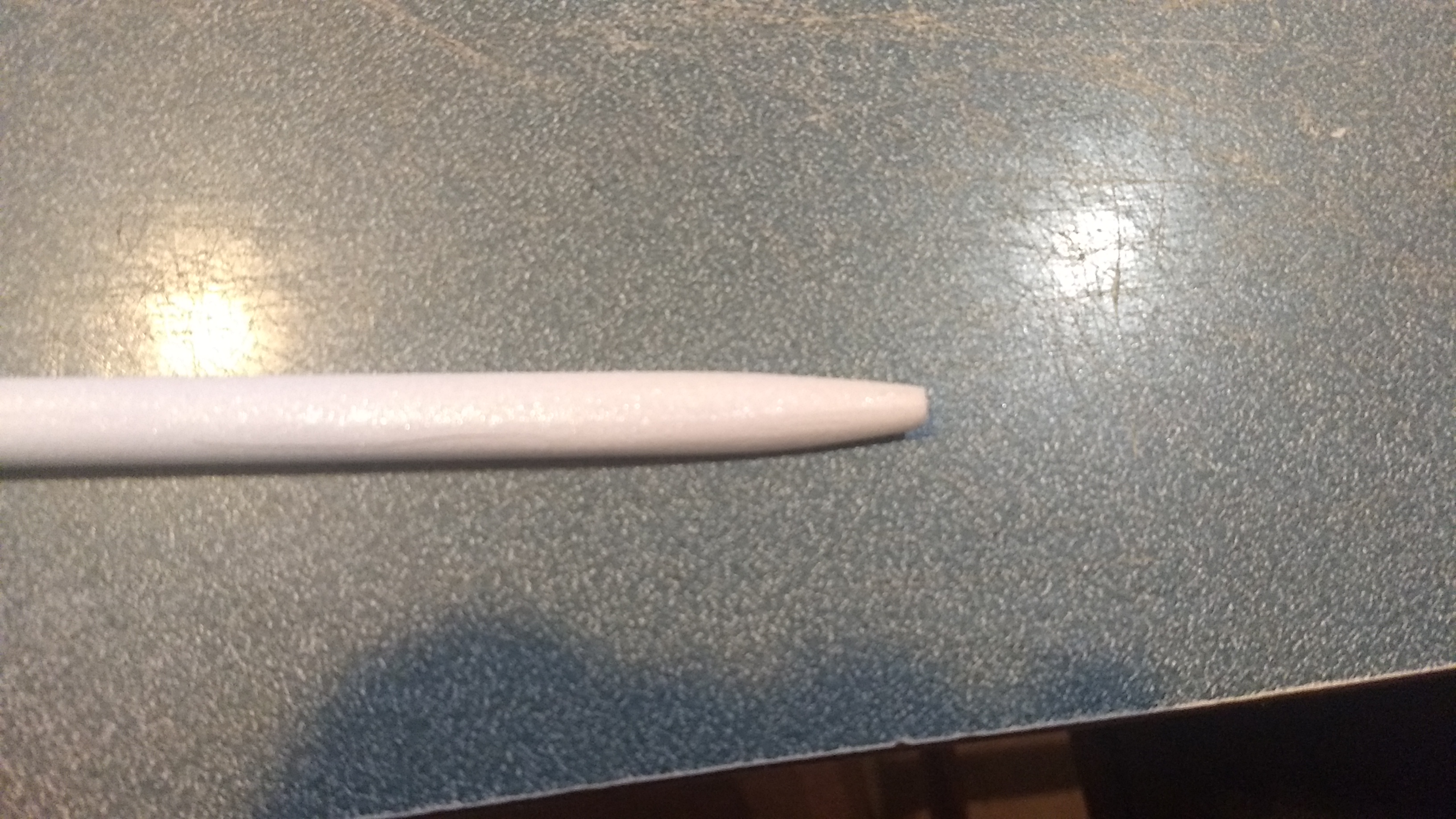
- Using the two remaining 3/8″ wide strips cut/fit one to to fit from the the front of the wing to the tail. Note the rear of the conduit is angle cut to match the vertical stab and it tapers slightly. Use the remaining strip to go from the front of the wing to the nose cone, again you will need to shape it to be pointed and tapered. The front and rear top conduit pieces should be sanded round before gluing, carefully sand the top of these conduit pieces round then glue them in place. It’s hard to sand them to a rounded shape after gluing them in place. Take your time.
- Glue the two pushrods in place into the pre-punched holes in the bottom of the elevons, note the pushrod should be closest to the body tube. The pushrods are inserted on opposite sides of each control horn for this reason, it allows better attachment to the servos.
- Apply glue to the tops of the control horn prongs to lock them in place.
- I put a little CA on the inside of the rear of the body tube right behind the rear rail button, this is to protect the tube as it sits on the rail standoff to prevent it from being damaged, this is optional.
- The basic construction is now complete.
Radio Installation
Note: Your radio needs to be configured for Delta mixing, this means that the servo arms will move the same direction during elevator stick movement and opposite for aileron stick movement. Connect your servos to the receiver one in the aileron connection and one on the elevator connection and apply power. Use a servo arm at least 9/16” long and with holes small enough that there won’t be slop with the pushrod wire when installed. I use the hole furthest out on the servo arm, to maximize movement. On the hs-65 hb servos there are is a long two-ended servo arm, I used that arm and trimmed off one end. Zero out any trim settings on the transmitter.
- Attach a 24-36″ servo extension to each servo(long enough to reach the front of the model), connect them to the receiver and power up the radio.
- Connect each servo to a pushrod and tape them in place underneath the horizontal stab with the control surfaces level.
- Look at the model from the rear. Moving the transmitter stick back(up elevator) should move both elevons up. Moving the transmitter stick to the right should move the right elevon up and the left elevon down. If you can’t get the servo reversing to give you the right polarity try swapping aileron/elevator inputs to the receiver. If that is correct, continue..
- Make sure the control surfaces are centered. Apply glue to the bottom of the servo and glue it in place in the pocket against the bottom of the stabilizer. Make sure the glue is set before continuing.
- Cut a 1/8″ by 1/2″ long slot just ahead of each servo in the body tube to route the servo wires to the front of the model. Route the wire inside and re-connect to the receiver.
- Use the included Velcro to attach the receiver as far into the nose cone as you can reach with your hand, this helps CG. Use velcro to attach the battery as far forward into the nose cone as possible still allowing you to plug and unplug it into the receiver connector wire.
- Power up the radio again.
- Make sure the control surfaces are neutral, adjust with trims or sub-trim as needed, then measure the control surface movement. Full elevator and aileron movement should be 1.5” in each direction. Since the model will be nose heavy, extra elevator movement helps to give sufficient authority during glide.
- If you have a flap/elevator mix you can program up elevator to a switch setting. The model needs approximately 1/2” of up elevon during glide. If you can’t set the up elevator trim to a switch on your radio you’ll have to manually put in boost and glide trim which is hard to do while flying the model.
- I used a fine line sharpie for a few panel lines on the model.
- You can paint the nose cone with any type of paint safe for plastics.
- I recommend leaving the body tube and control surfaces in the white, paint adds a significant amount of weight and this model has a higher wing loading than my other kits.
- Re-install the receiver and battery if removed for finishing.
- Insert your heaviest loaded rocket motor into the motor mount
- Support the model at the balance point indicated for boost. I use two chopsticks with small 1/2″ square foam pieces pressed onto the pointy end and held in place with two small vices. I can adjust the placement of the vices on each side to clear the ramjet tubes. Place the model right side up on the chopsticks at the balance point indicated above. Use the included lead weight as needed glued as far forward in the end of the nose cone as possible to balance it. Secure the weight with CA to hold it in place once you determine the correct amount.
- Do not try to fly the model with it balancing it behind this point. The adage is, a nose heavy model flies poorly, a tail heavy model flies once.
Flying: See the Instruction/Information link at the top for flying instructions Be ready on the first few flights to keep the model straight till you have the trims set perfectly for boost and glide.
-
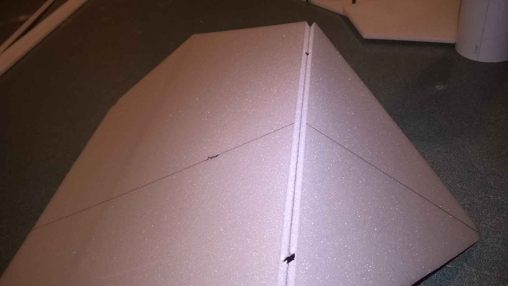
- Unfold wing and glue taped joint
-
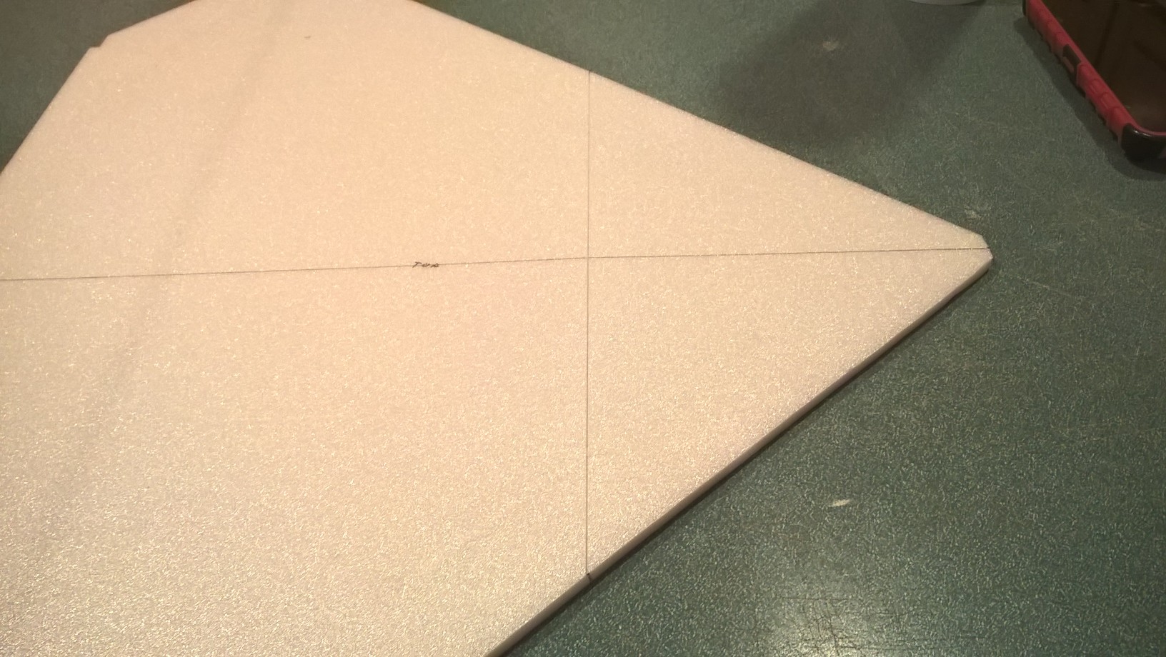
- Make sure wing stays flat
-
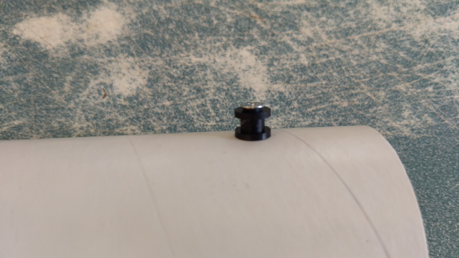
- Install the front and rear rail buttons.
-
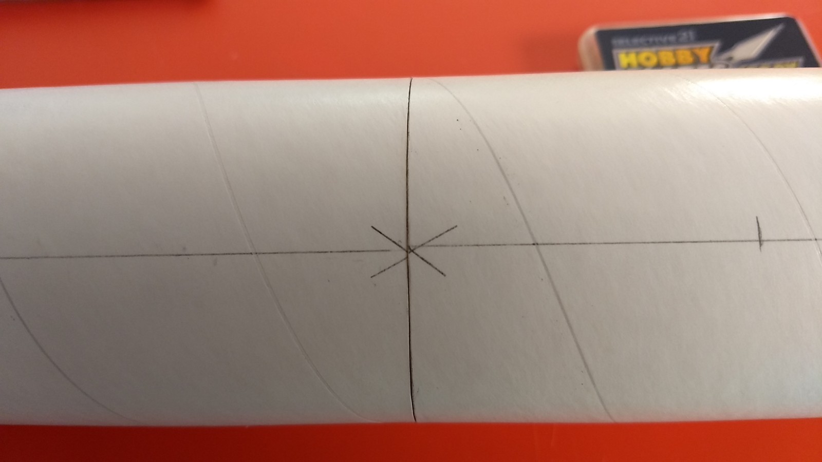
- Join the two body tubes keeping the arrow marks aligned.
-
- Glue the horizontal stab to the body tube even with the rear of the tube.
-
- Add the medium reinforcing strips on each side of the horizontal stab.
-
- Glue the wing in place.
-
- Add the long reinforcing strips on each side of the wing.
-
- Glue the motor mount in place and then add the reinforcing strips on either side.
-
- Glue the foam circles into the front of each ramjet tube. The front is the end with the holes for the ramjet supports.
-
- Using the paper templates make two ramjet cones.
-

- Glue the cones to the foam disks on each ramjet and reinforce with foam safe CA to harden the cone.
-
- Insert the two short rods into each standoff
-
- Glue a standoff to each ramjet pod
-
- vinyl wraps applied to each ramjet and the intake cone painted.
-
- Glue the ramjets into the pre-punched holes
-
- Glue the vertical stab in place
-
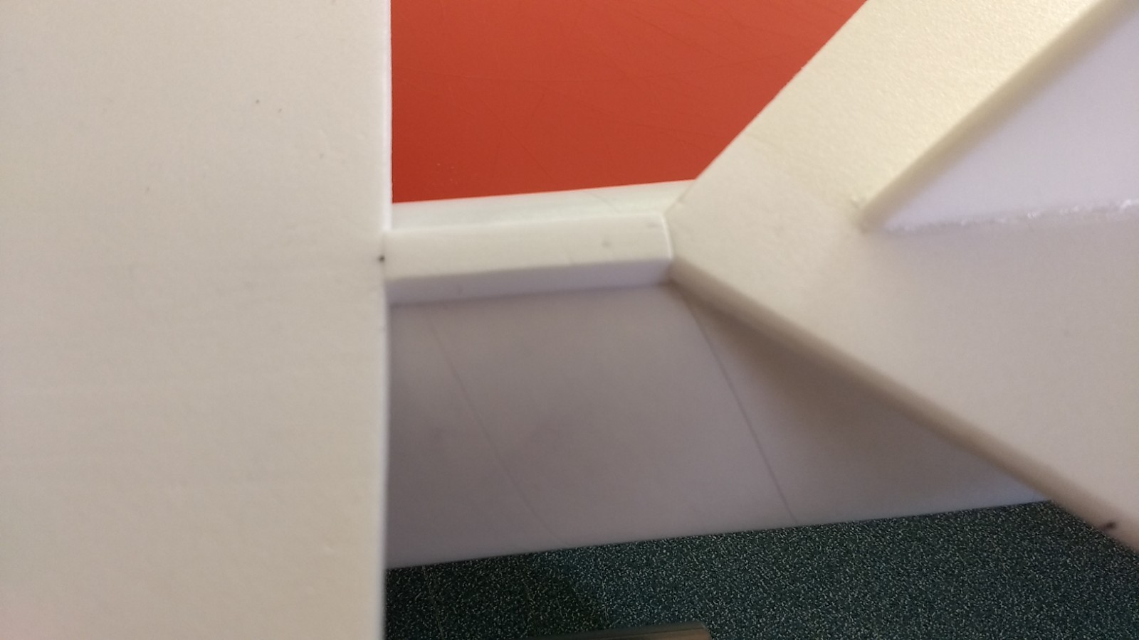
- Glue the vertical stab in place then cut and fit the little filler piece between the wing and horizontal stab from the 3/8″ strips.
-
- Shape then add forward conduit lower portion.
-
- Front top conduit.
-
- rear top conduit
-
- Fitting the foam conduit at the rear
-
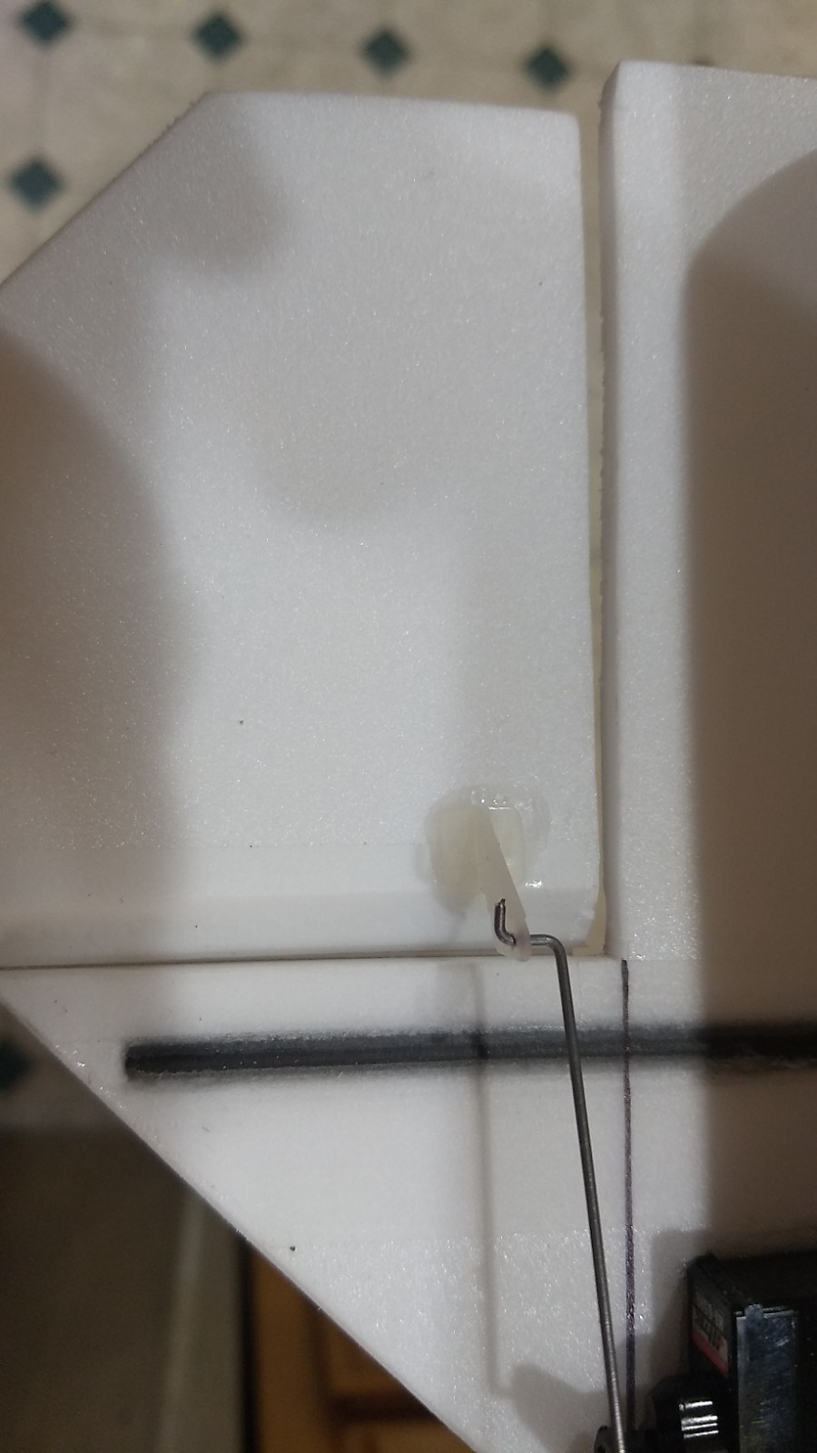
- Install each control horn/rod, note the pushrod is next to the body tube.
-

- add glue on the top of the control horn prongs to lock them in place.
-
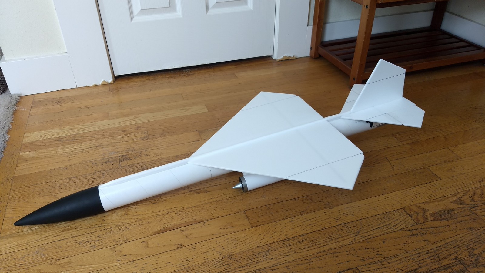
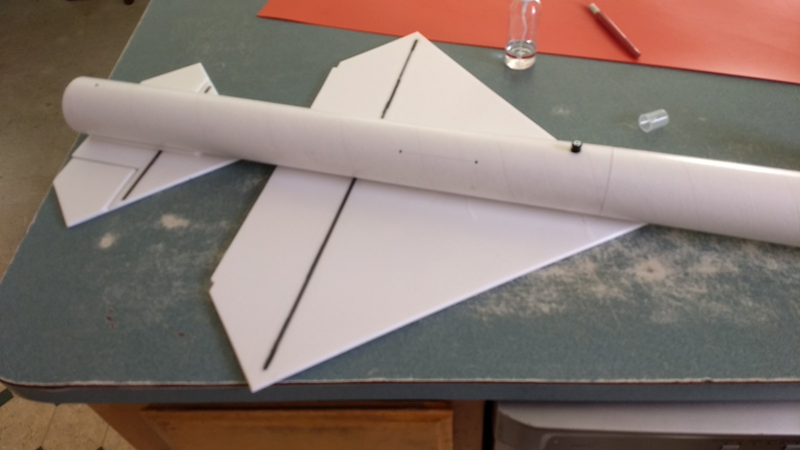
- Completed airframe.
-
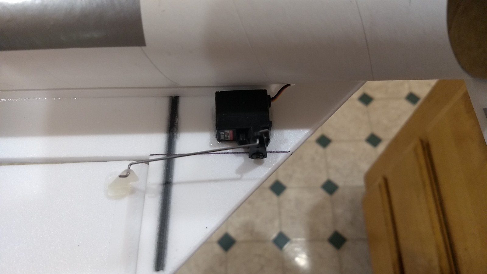
- Glue the servo in place keeping the control surface level.
-
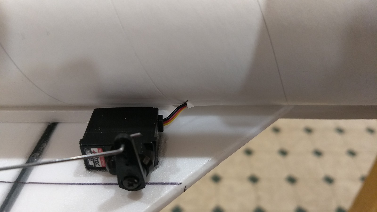
- Cut a slot and route the servo wire into the body tube and forward to the end, connect it to the receiver, then attach the receiver
-

- Attach the receiver and battery inside the nose cone
-
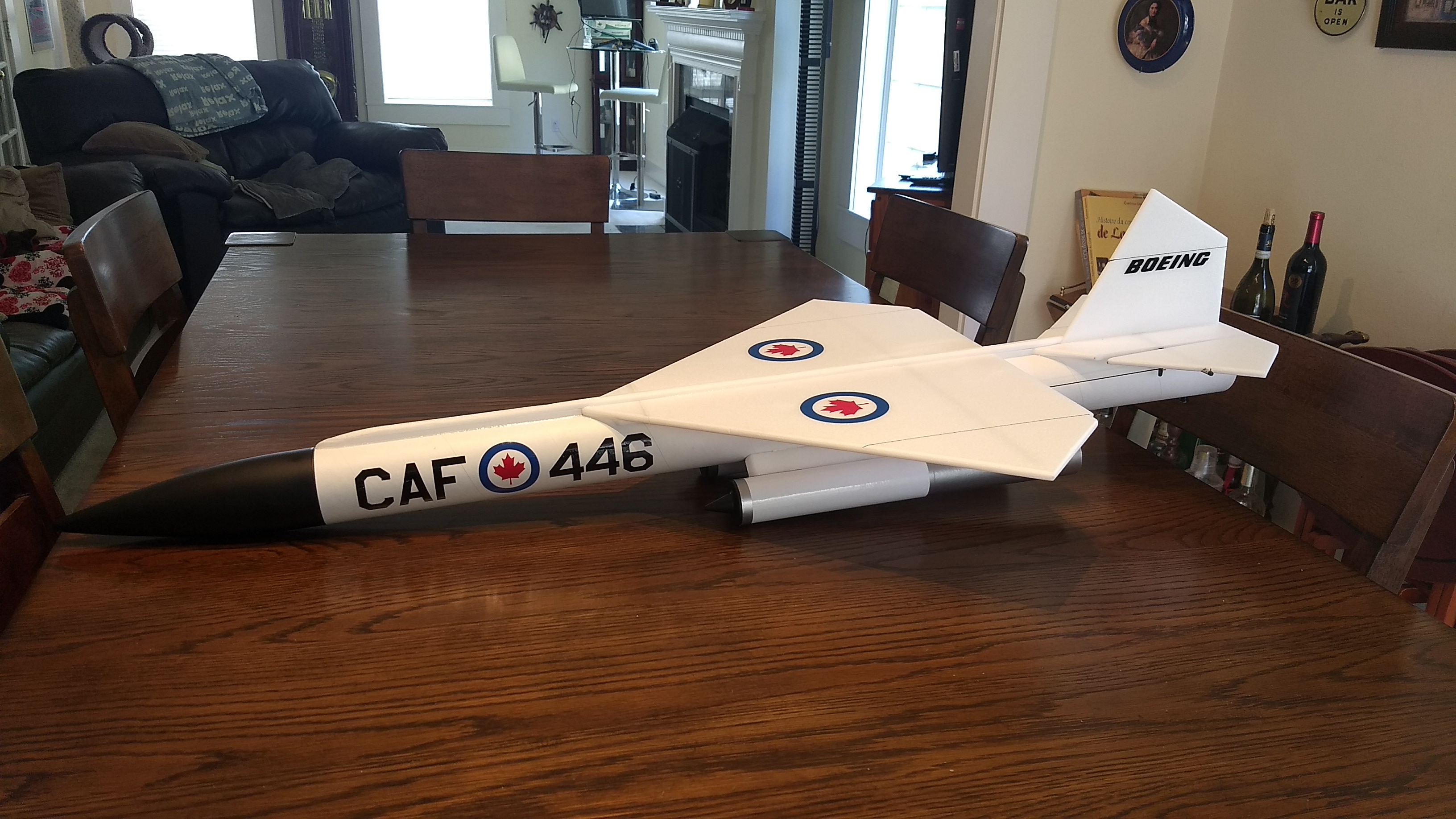
- Canadian Markings
-
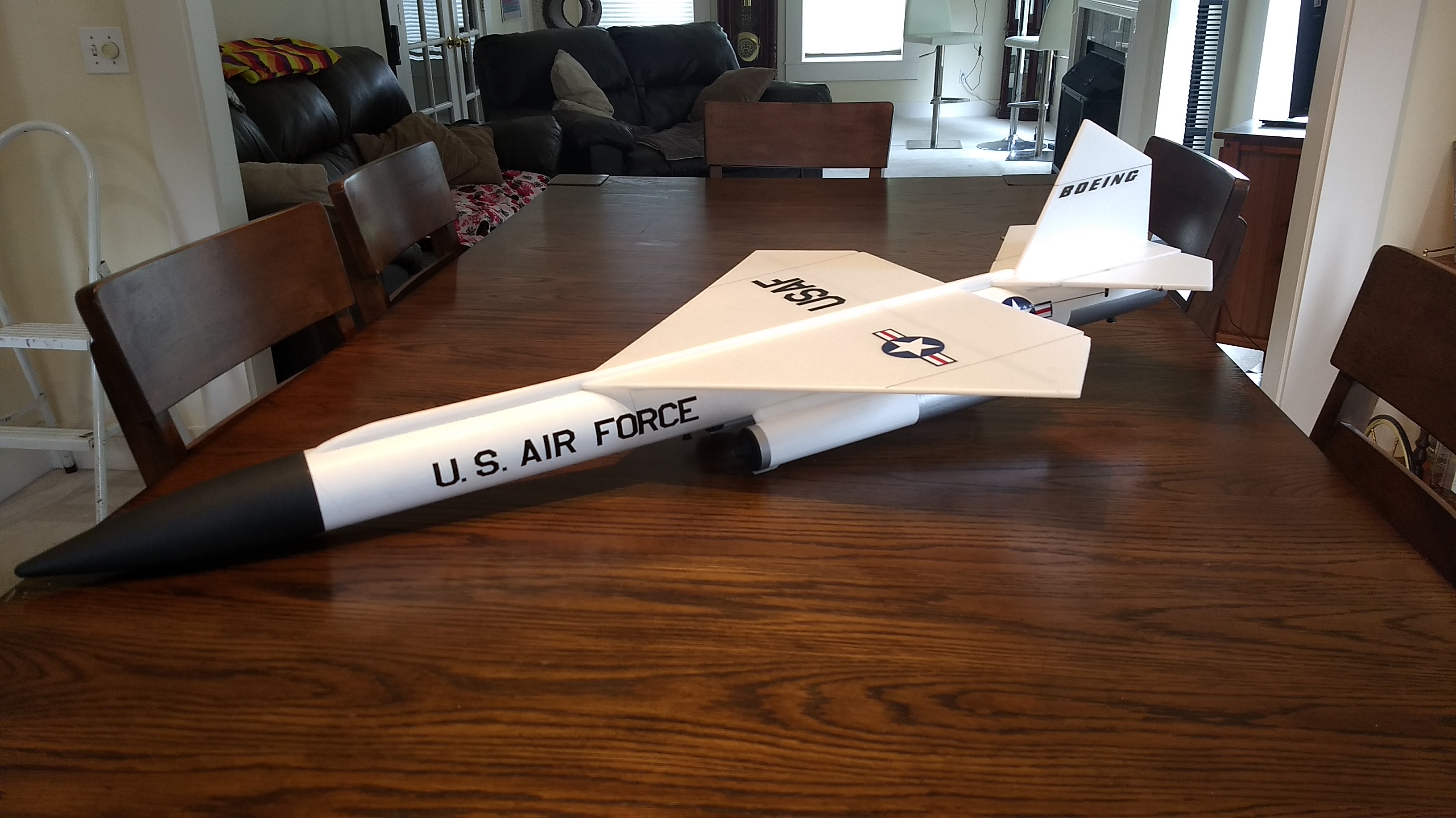
- US markings
-
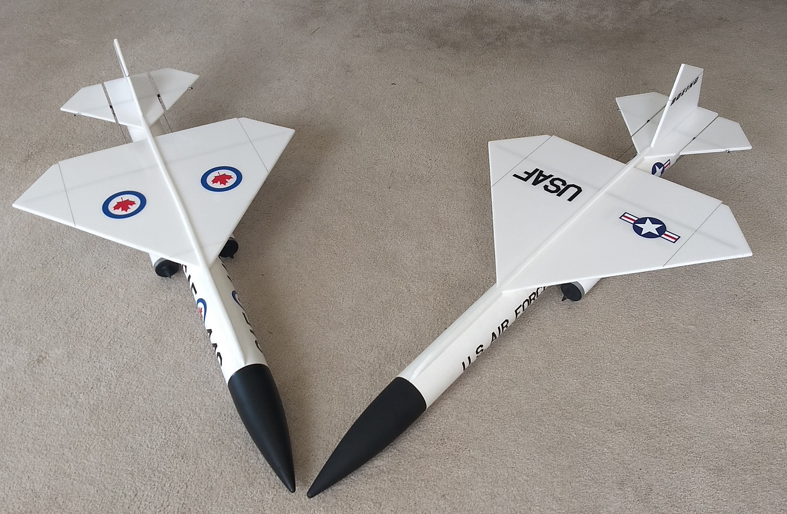
- US and Canadian Versions
-
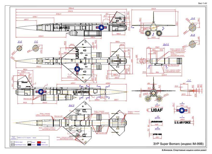
- bomarc B model
-
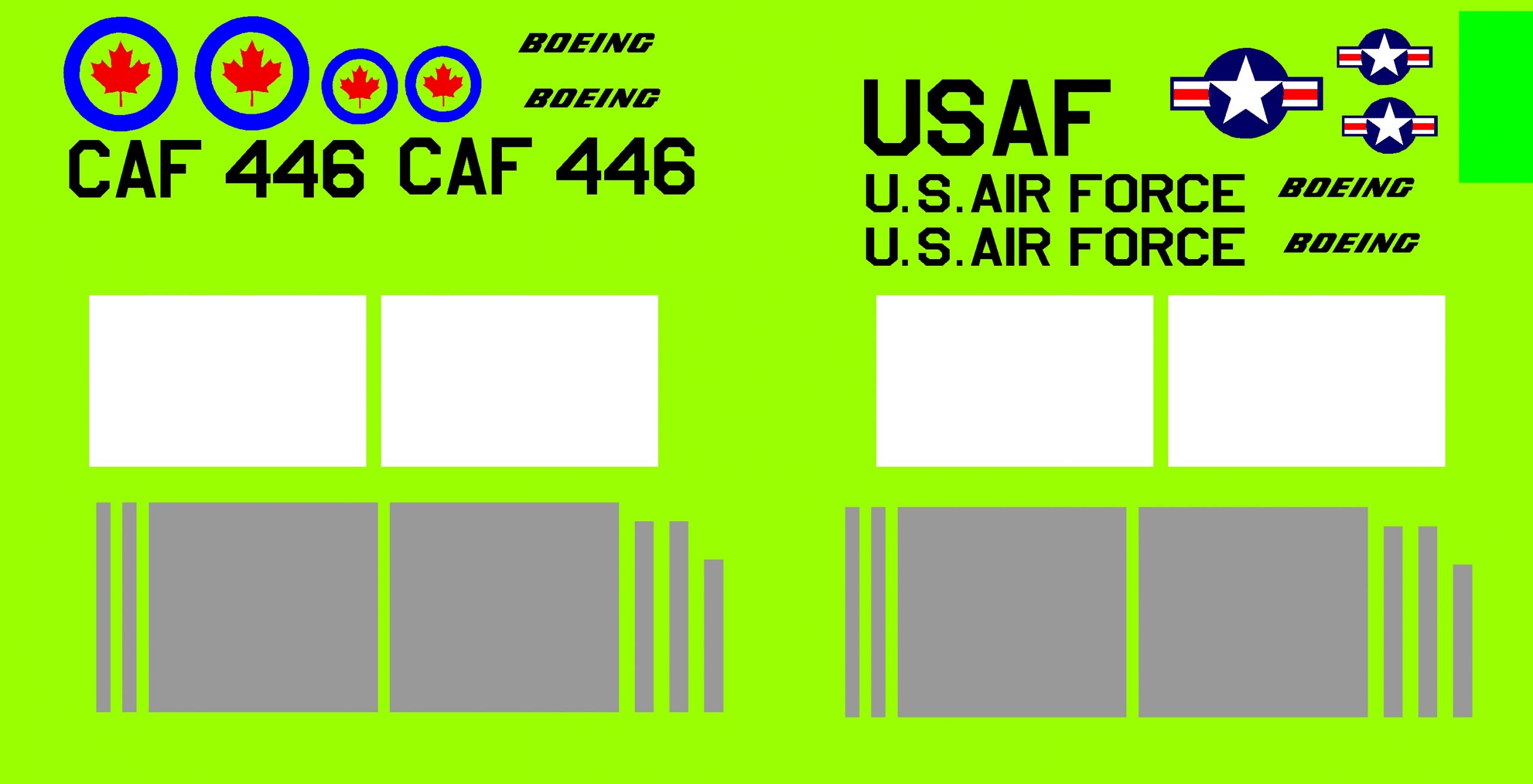
- Example of the stickershock decal options.