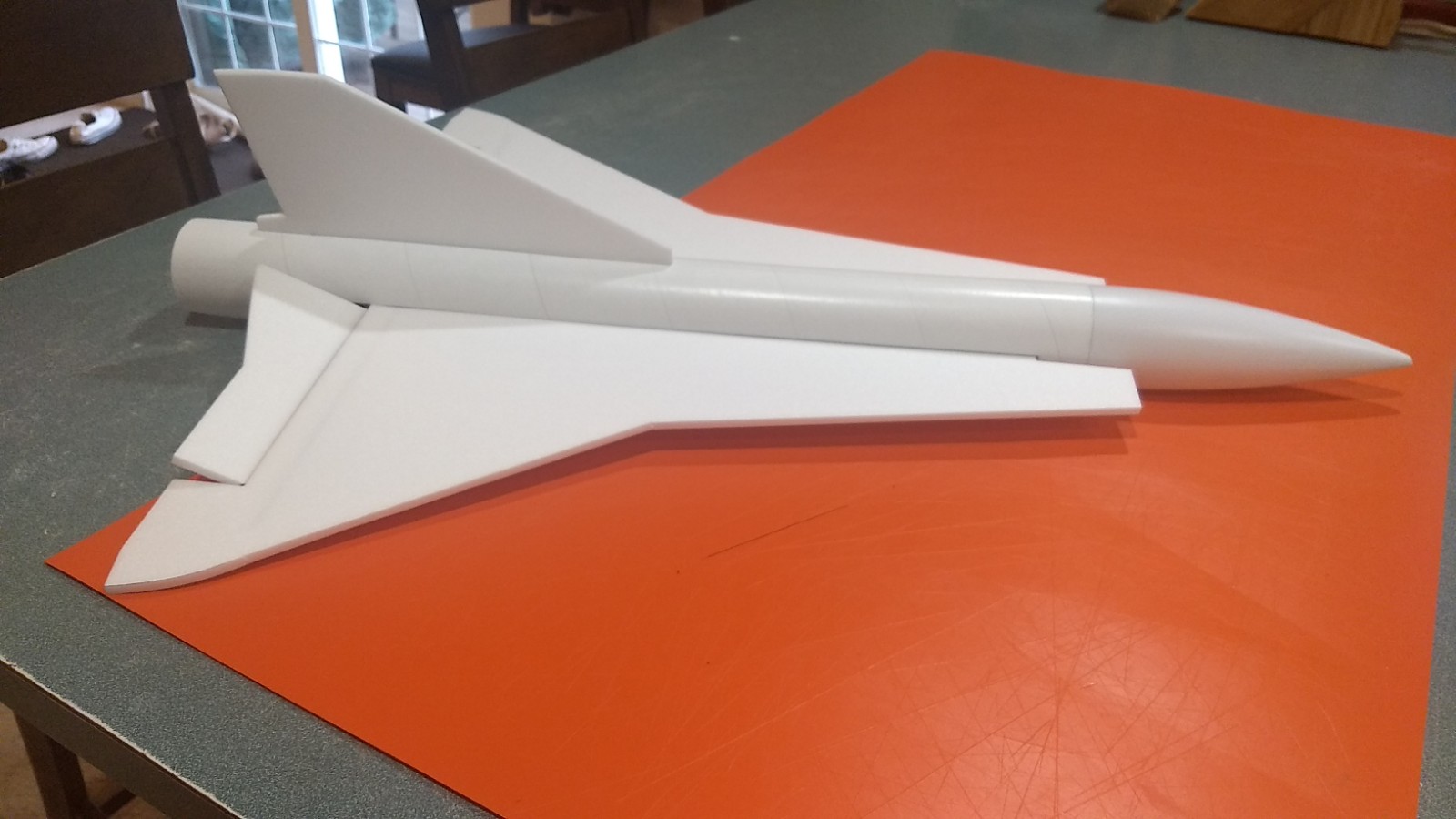
 The Saab J-35 RC Rocket glider kit is modeled after the unique Swedish cold war Mach 2 Fighter/Interceptor. Kits come with a plastic nose cone, 2.6″ white tubing for the body, 6mm depron wing and tail surface. Elevons are pre-hinged, rail button holes are pre-cut, spar slot is pre-cut and the body tube is pre-slotted for the tail and wing. Please refer to the General information for all kits tab above, then read these instructions completely before starting assembly. Length 32″, wingspan 22″, weight 10 oz rtf(painted) with rocket motor installed.
Decals for the Saab J-35 are available HERE
CG location for rocket flight ready to fly with motor and battery installed: 9.75″ to the rear of the leading edge intakes.
Unpacking your kit:
The kits are packed to protect them in shipping, but the contents are fragile so unpack carefully. Carefully cut the tape holding the tubes in the box, then unwrap/lightly cut the plastic wrap to free the tubes, the spar may be packed in the tubes and the baggie with the little parts and nose cone will be in the tubes as well. Carefully cut the tape holding the cardboard wing protector in the box and carefully remove it, don’t pull hard or bend it. Then carefully cut the tape holding the cardboard top piece to the bottom. There may be some sticky tape holding the cardboard to the bottom cardboard piece, carefully peel it being sure not to bend anything. Once the top cardboard is free you can see the foam wing/tail parts, there are little fragile pieces in here, so unwrap carefully. It may be best to use an exacto to lightly cut the plastic wrap and carefully remove it without cutting into the foam. Make sure everything is free before you remove the pieces to avoid breaking anything. Kits contain one or two scrap pieces for repairs if you damage anything in construction or flight, just cut and patch in a spare piece of the foam if needed using foam safe CA+.
Welcome to the world of rocket boosted radio control gliders. This is not a model for a novice RC pilot, but anyone who is comfortable with RC flying of a medium speed model should be fine. Read through the instructions, look at the photos and be sure you understand the step before committing to cutting or glue.
Identify all pieces, the kit should contain:
1 wing taped together
1 Nose Cone
1 vertical stabilizer
1 spine fin
2 foam conduit strips
2 canopy halves
1 wing spar
1 roll blenderm
2 control horns/Pushrods
1 Body Tube
Motor mount
3 13/16″ x 2.5″ wide strips to center the motor tube
Velcro(for battery and rx/bec attachment)
Lead weight
Notes before starting:
Foam safe CA+(Bob smith super gold + is good) is the only glue recommended for construction. You will also need foam safe accellerator to set the glue.
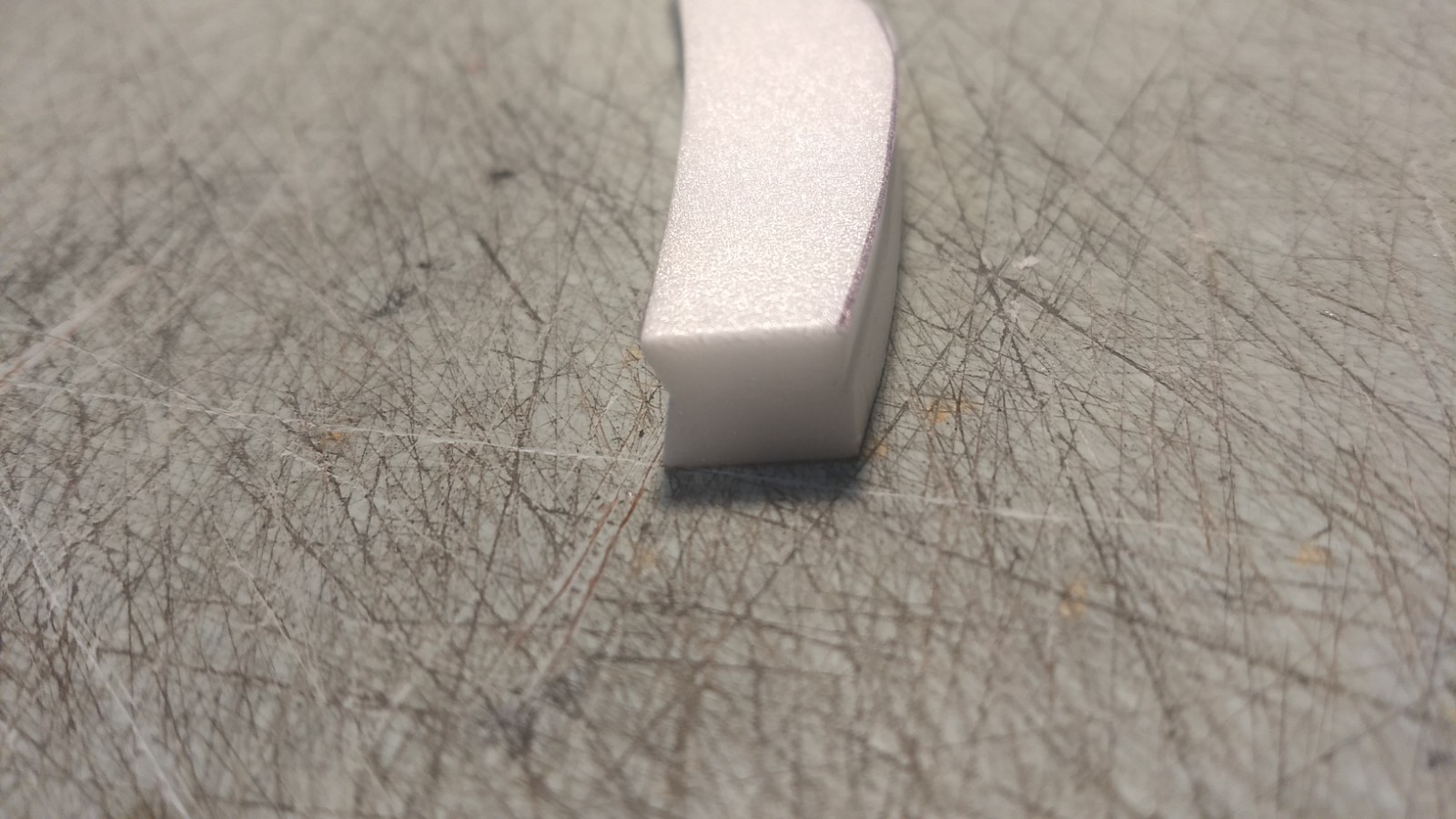
I now prefer to bevel the edges of the foam instead of sanding, it’s quicker, less messy and you don’t risk tearing the foam edge. I use a thin straight edge and exacto knife cut a 1/16″ wide bevel on top and bottom of the surfaces. Before assembly you may bevel the leading and trailing edges of the wing, the leading and trailing edges of the vertical stabilizer. For the cockpit and spine conduit, you may use 320 grit sandpaper and a sanding block to round the edges of the foam, just go slow and do little bits at a time and use a light touch. Note for the conduit and cockpits there is a beveled edge and the there is a left and right side, look at the bottom edge it should be bevel cut they should be marked on the side to glue make sure the V notch is correct when gluing, then sand the upper edges round only. See pictures for clarity.
Assembly:
- Glue three 2.5″ long foam strips on the motor tube using foam safe CA+. These help center the motor tube in the body tube once you insert it into the body tube. Note the tabs will be on the sides and bottom of the tube, the fin tab will make contact on the top of the tube. Refer to the picture. If your kit came with a motor block glue this in the front of the motor tube at this time. The lines drawn on the motor tube are for reference but may not be perfectly aligned, use your eyeball to make sure they look as in the picture.
- Install the two rail buttons in the pre-cut holes in the body tube at this time.
- Unfold the wing and glue the taped joint, then glue in the spar into the slot, once cured tape over the spar and center wing joint with the included blenderm tape.
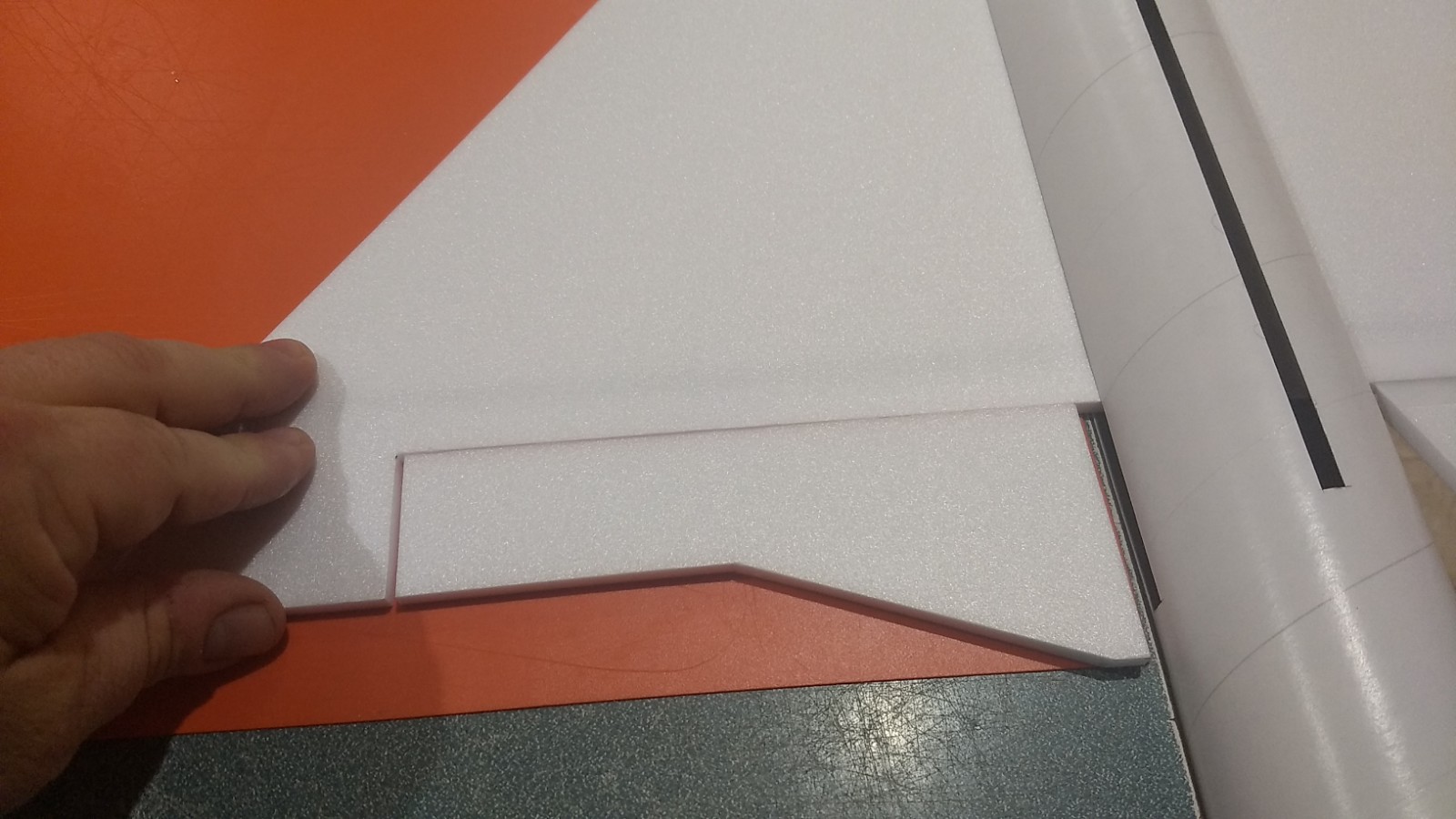
- The wing has one elevon not installed, that is so that you can insert it into the body tube, you will insert it, slide it forward, then tape the elevon in place, then glue the wing in place. The rear of the body tube slots have two tabs that are folded in, these are so you can get the wing in place, then slide it forward as far as it will go, then you will fold the tabs back down from the inside and glue them in place to plug the slot. Make sure the spar is pointing down and the vertical stab slot in the body tube is pointing up.
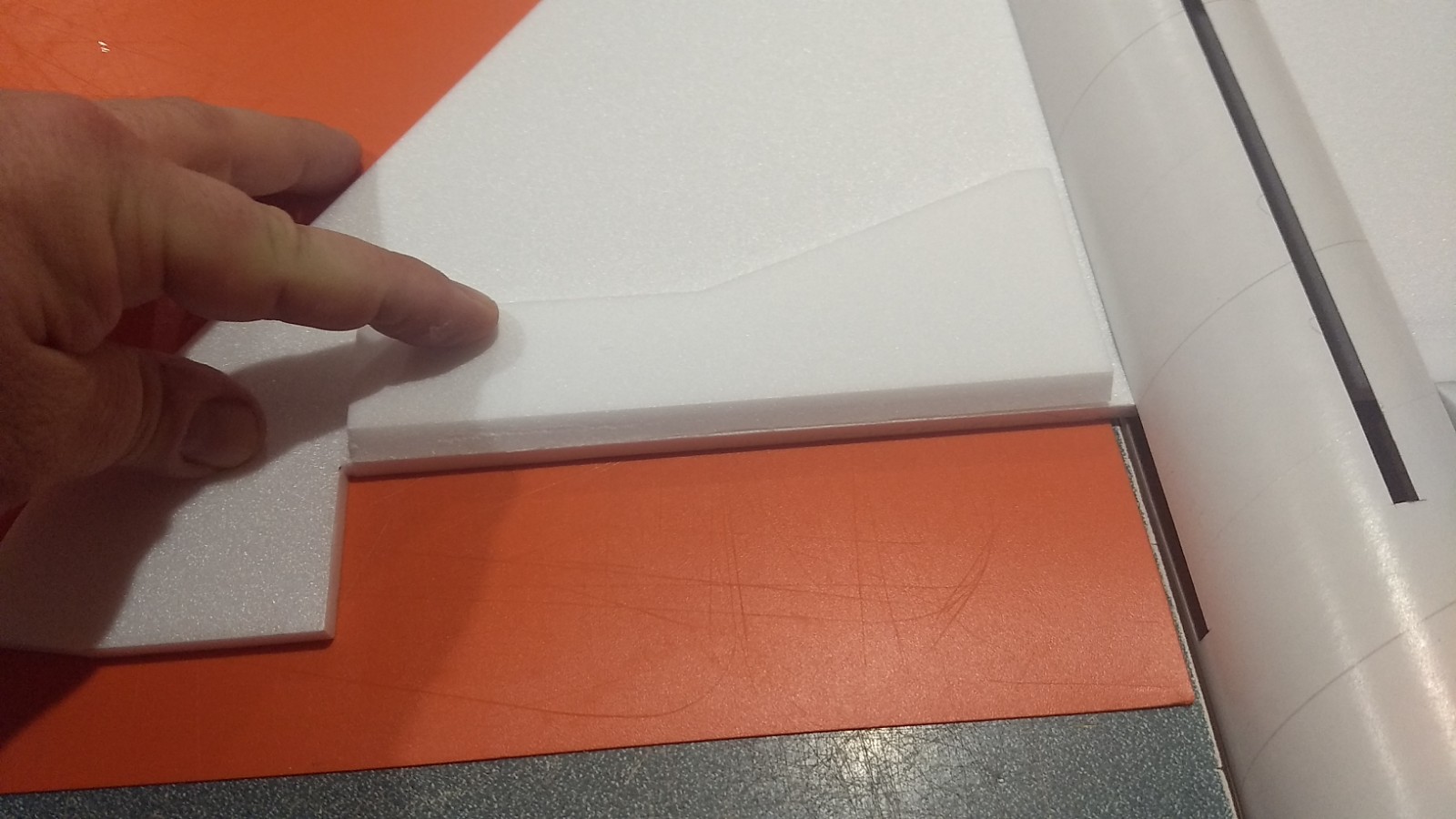
- Fold the slot tabs up out of the way then insert the wing with the non elevon side into the slot keeping the wing all the way to the rear till it is halfway in, then slide the entire wing forward till it stops, the front intakes will stick past the front of the tube. Fold the little tabs back down behind the wing.
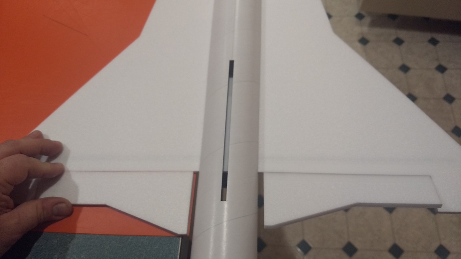
- Tape the elevon in place: Lay the wing on a flat surface with the rest of the model hanging over the side, it helps to have some help to do this. Lay the non attached elevon with the bevel cut down and against the cutout in the wing but with a very small gap. The outboard end of the elevon should have a 1/16″ gap to allow free movement, Tape over the joint with the included tape.
- Flip the elevon forward so it sits on the top of the wing and then tape over the joint, I tape about 3/16″ ahead of the bevel, over the bevel and wrap around the bottom of the wing. Make sure the surface can move freely or re-do the joint.
- Now center the wing at the front and back and tack glue in place. Make sure the elevons can move freely and the wing is all the way forward. A little at a time apply a glue fillet on both sides of the wing and on the bottom as well. It may help to hold the tube and sqeeze in a bit or press down to make sure it contacts the wing.
- Using a gloved hand, support the little tabs in the wing slots flush from the inside of the model and apply glue to the outside to secure them in place. Just enough to hold them, the motor mount will insert and press in from the inside as well.
- Glue the vertical fin into place. Make sure the vertical fin is straight up and down using a triangle or something similar. Apply a light filet to both sides of the vertical stab on the inside and outside of the body tube.
- Back out the rear rail button screw so that the screw is flush or below the t nut inside the tube, this is so you can slide the motor mount over the t-nut.(on later kits the hole may be moved forward so you don’t have to loosen the rail button screw)
- Test fit the motor mount into the body tube and under the fin tab. Make sure it fits, or sand the foam tabs lightly. Screw in the rail button screw now, it will crush the motor mount tab a bit but will not harm anything. Then glue the motor tube in place, it will stop against the rear of the wing. Put a fillet on each side of the motor mount tabs and fuselage.
- Apply CA to the inside top of the rear body tube to protect it from motor exhaust.
- Glue the two canopy halves together, note they have a v notch cut in the bottom to make fitting easier.
- Glue the two conduit halves together, they also should have a v notch cut in each half to make fitting easier.
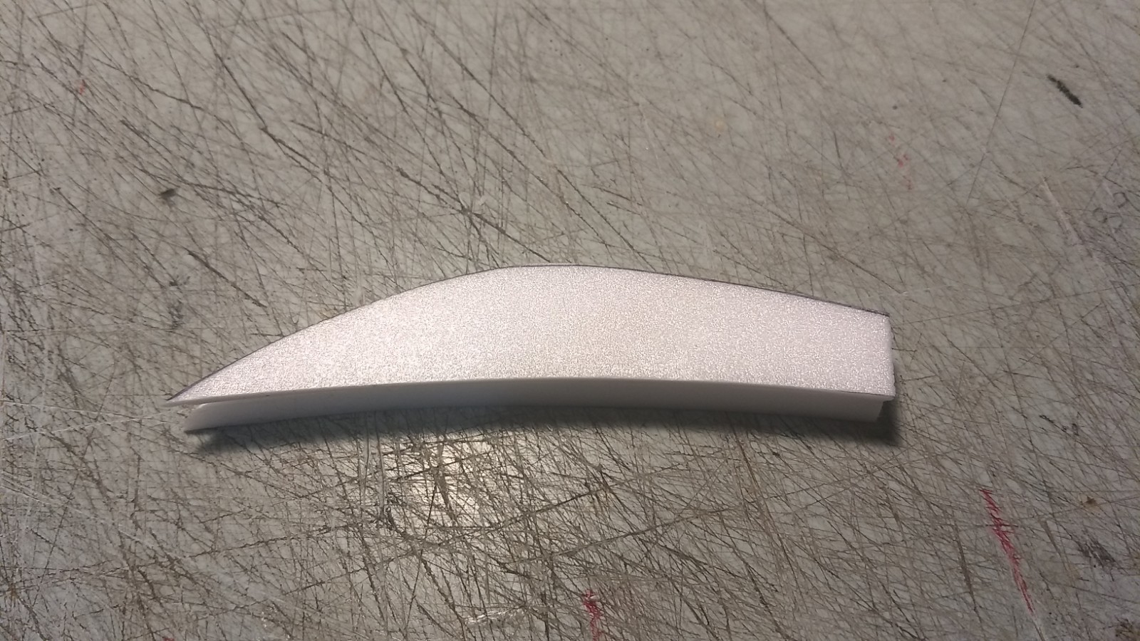
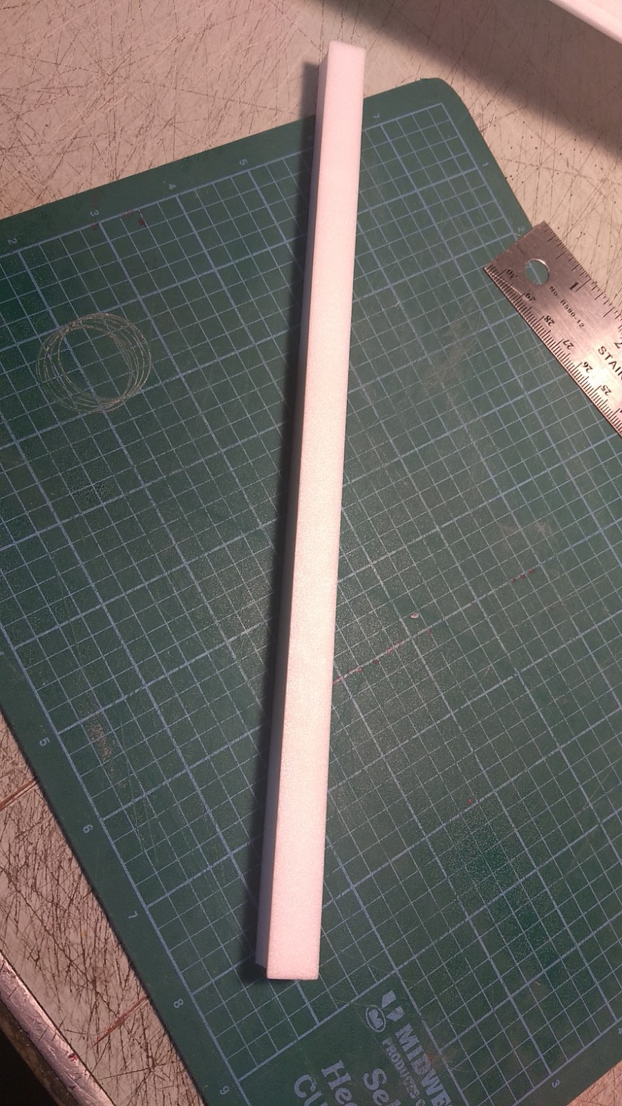
- Sand the conduit round on top and taper the rear to match the thickness of the vertical stab.
- Sand the canopy round.
- Glue the canopy to the nose cone, the rear of the canopy should be even with the rear of the nose cone when it is inserted into the body tube.
- Fit the conduit so that it butts against the vertical stab, you will need to sand the rear to a taper to match the thickness of the stab, and trim the rear so the front butts against the cockpit when the nose cone is in place, glue the conduit in place.
- Cut a slot then glue the styrene spine fin in place 1.25″ ahead of the front of the vertical stabilizer, make sure it is straight and lined up with the stab. It inserts about 3/16″ into the foam.
- Apply CA+ to one of the control horns and press it in place on the BOTTOM of the control surface in the pre-made holes. Note The control horn holes face forward and the pushrod should be closest to center of the wing. Repeat for the other side. Apply a fillet around the control horn on the the prongs on the top of the wing to lock them in place. See photos.
- The unsupported parts of the wing that stick out next to the nose cone can be a bit fragile if you aren’t careful handling the model, if you are worried you can wrap some tape around the top and bottom of that part of the wing before finishing to help give it some more strength. Or you could glue a 3″ long piece of popsicle stick on the bottom etc.
The basic construction is now complete.
Radio Installation
Note: Your radio needs to be configured for Delta mixing, this means that the servo arms will move the same direction during elevator stick movement and opposite for aileron stick movement. Connect your servos to the receiver one in the aileron connection and one on the elevator connection and apply power. Use a servo arm at least 9/16” long and with holes small enough that there won’t be slop with the pushrod wire when installed. I use the hole furthest out on the servo arm, to maximize movement. On some servos there are a long two-ended servo arm, you can trim off one end and use that arm to get sufficient length. Zero out any trim settings on the transmitter.
- Flip the model upside down. Connect each servo to a pushrod. If the pushrod is too tight, you can use twist an X-Acto knife in the servo arm hole to make it larger, but be careful and do not make it too large. Each servo should be on the bottom of the wing, with the servo electrical wire pointing forward and the servo arm pointing toward the wing tip. Tape each servo in place so that the control surfaces are centered. With the model right side up look at it from the rear. Moving the transmitter stick back(up elevator) should move both elevons up. Moving the transmitter stick to the right should move the right elevon up and the left elevon down. If you can’t get the servo reversing to give you the right polarity try swapping aileron/elevator inputs to the receiver or turning the servos over and swapping the servo arms to the other side of the output shaft. If that is correct, continue.
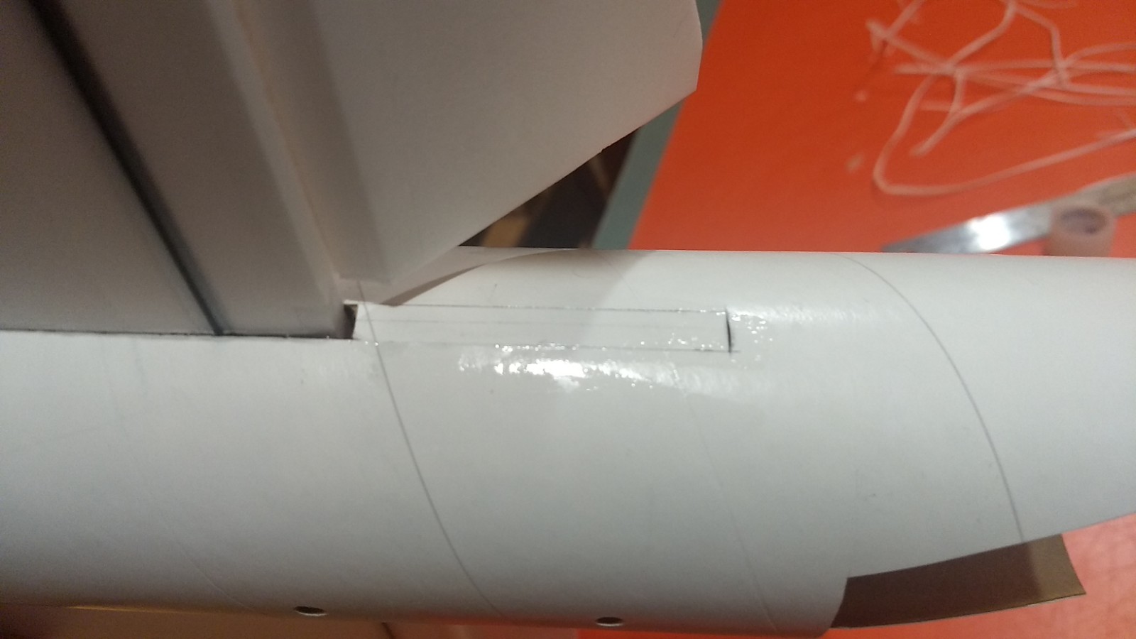
- Measure where the servos will hit the body tube.
- Cut a pocket into the body tube and removed the cardboard and glue. Attach a 12-16″ servo extension onto the servo and pass it through the pocket to the front of the model and attach it to the receiver. I used velcro included to attach the receiver inside the top of the nose cone. The battery is held in the bottom of the nose cone inset about 1″.
- Glue the servos in place. With the radio still on, put a moderate amount of glue on the servo, being careful not to get any near the output shaft, and set it in place on the wing and in the pocket keeping the control surface centered. Do the same to the other side. Let it cure being careful not to get any glue near the output shaft of the servo.
- Make sure the control surfaces are centered, use trims if needed. Now measure the control surface movement. Full elevator movement should be 1/2 to 5/8″ in each direction, aileron movement should be 3/8″ in either direction. I used a rate of 65% for aileron and 100% for elevator using the outermost hole in the hs-65HB dual arm horn.
- If you have a flap/elevator mix you can program up elevator trim for boost and glide. If you can’t set the up elevator trim to a switch on your radio you’ll have to manually put in boost and glide trim using the trim tabs which is hard to do while flying the model. My model needed approximately 1/4-5/16″ of up trim for glide. My particular model needed just a small amount of down trim for boost, I used down 5 for boost and up 32 for glide on my dx-8 gen2 settings.
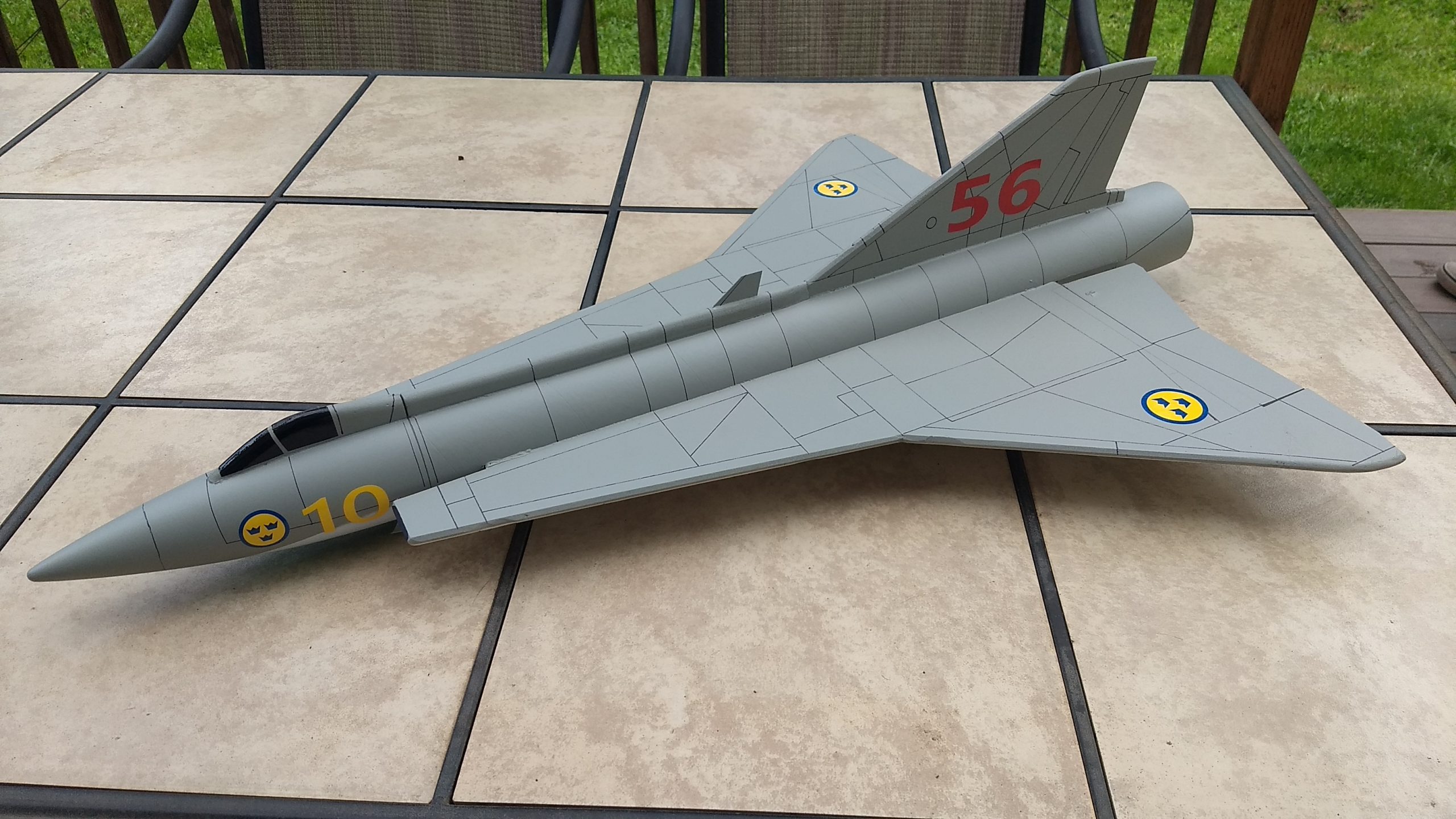
- If you decide to paint your model, I can only recommend testors/model master enamel spray at this time, others I’ve tried damage the foam surface. I recommend flat colors as they dry faster and the surface imperfections of foam aren’t as noticable. Paint typically adds 1/2 to 3/4 oz. You can use a black fine line sharpie to add panel lines or rivet detal if desired.
- If you choose to use the stickershock markings, after application use a hair dryer on hot to warm the markings and them push them down into the foam surface with your finger. They will really conform and stick down well. The cockpit is applied as shown in the pictures, the left and right halves may meet at the top depending on how you rounded the foam, the long straight 1/4″ wide piece is to be used as a filler between the left and right halves at the top in case there are any gaps. The large roundels go on the outer upper wing panels, and inboard lower wing panels, the 56 goes on the tail and the 10 and small roundel goes on either side of the nose.
- Install your battery.
- Insert your heaviest loaded rocket motor into the motor mount
- Support the model upside down at the balance point indicated for boost. Glue supplied lead weight in the nose or tail as needed to balance it. Do not use all of the lead, just as much as needed. Do not try to fly the model too nose or tail heavy. Remember, a nose heavy model flies poorly, a tail heavy model flies once.
Flying: See the General Instruction link at the top for flying instructions. Be ready on the first few flights to keep the model straight till you have the trims set perfectly for boost and glide.
-
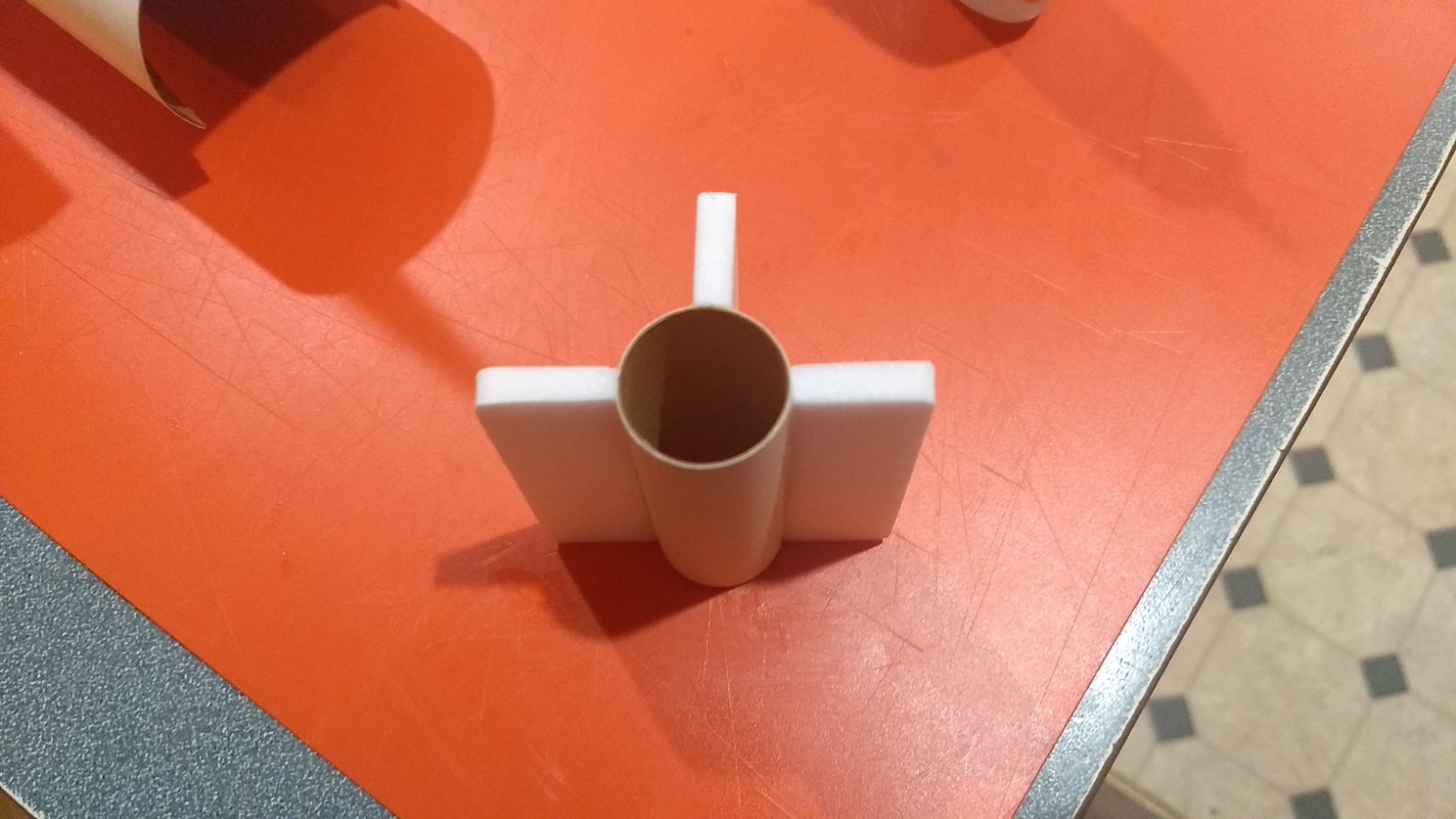
- Glue motor centering tabs on motor tube
-
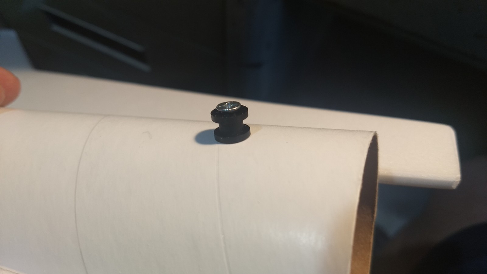
- Install front and rear rail buttons
-
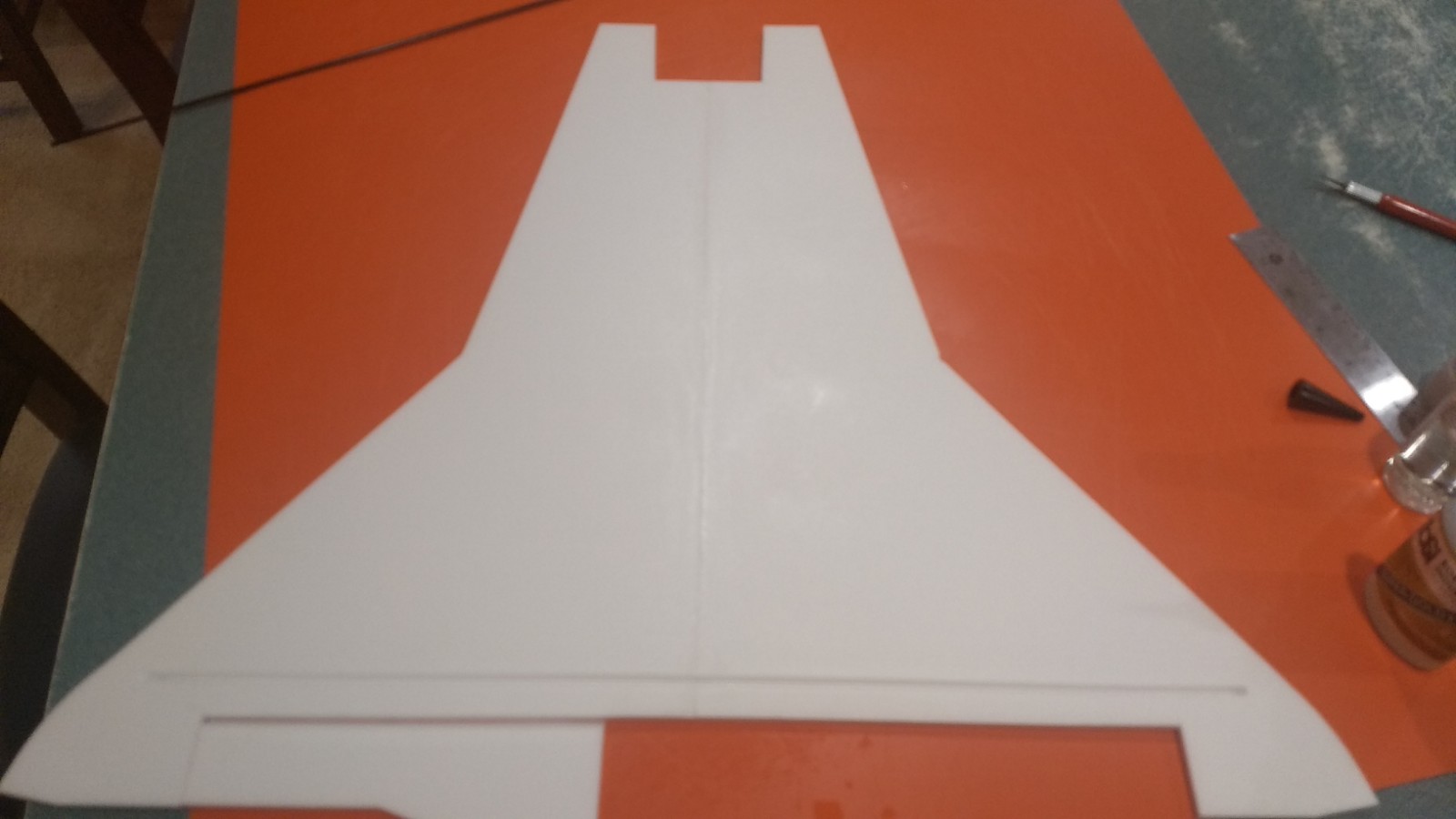
- glue taped joint on wing and lay flat
-
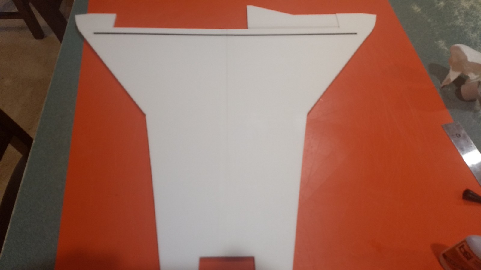
- Glue spar in place then tape over spar and center joint with blenderm tape.
-
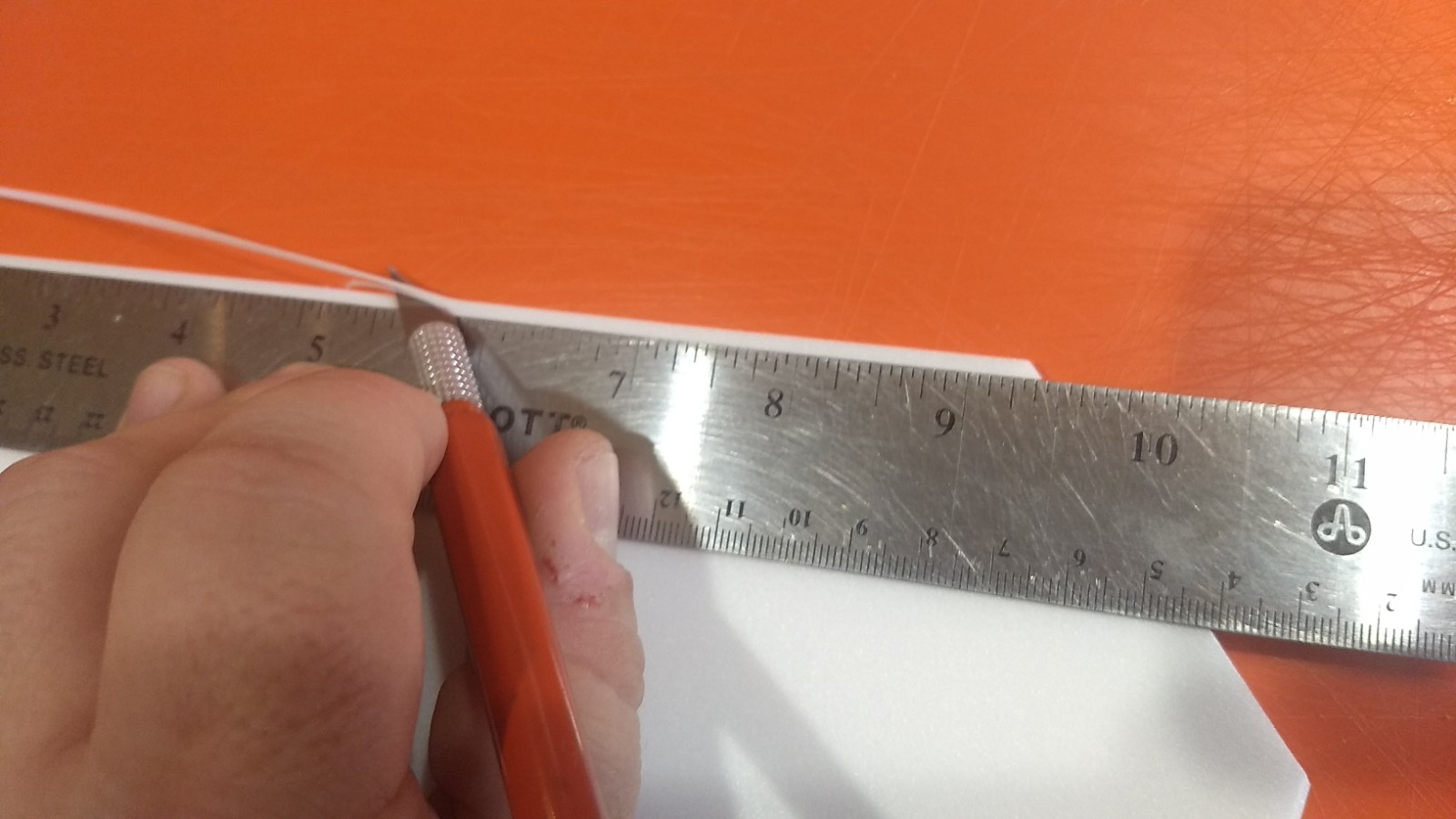
- Beveling the edges of the wing and tail surfaces.
-
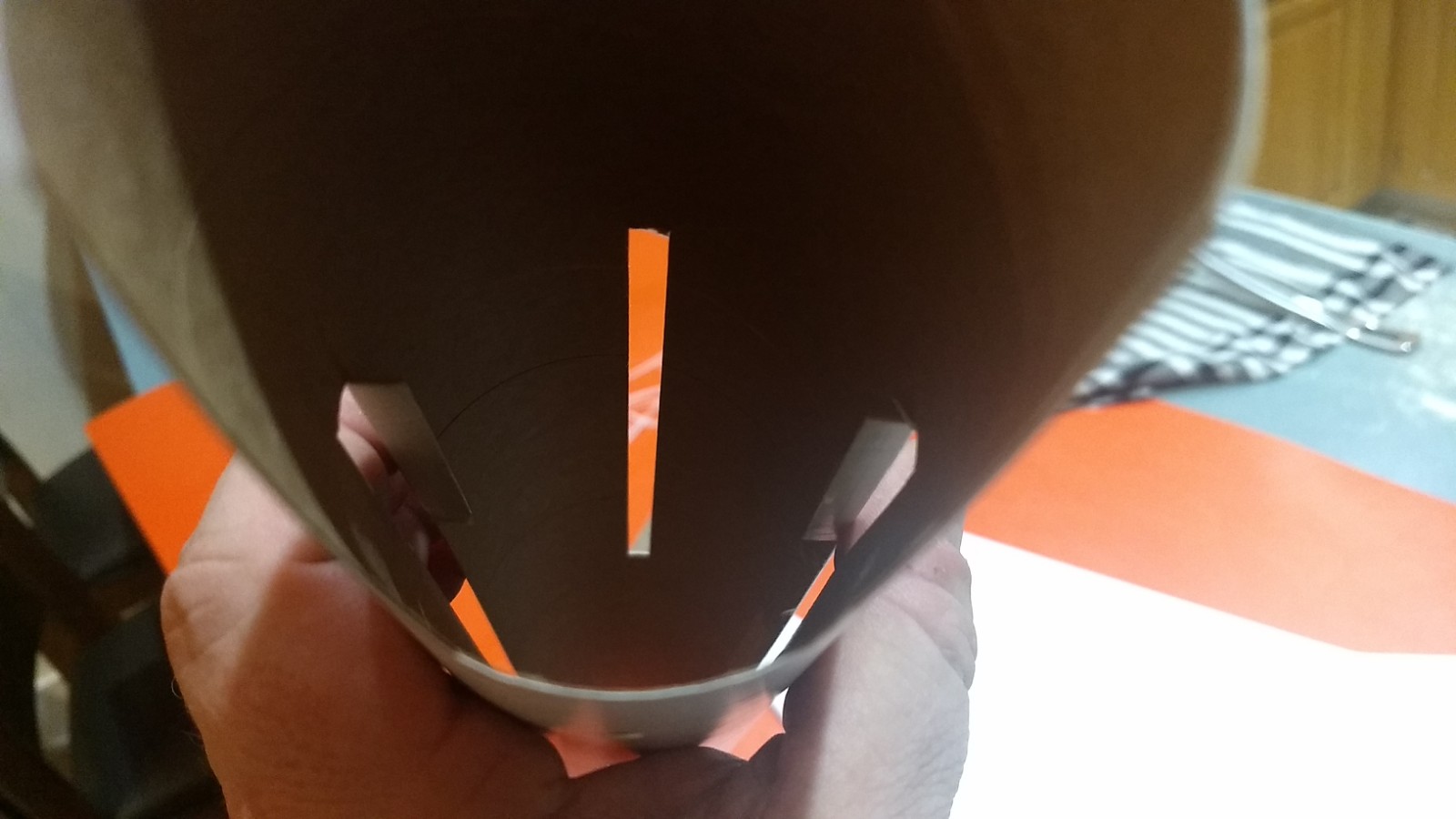
- Fold wing slot tabs up out of the way inside the tube.
-
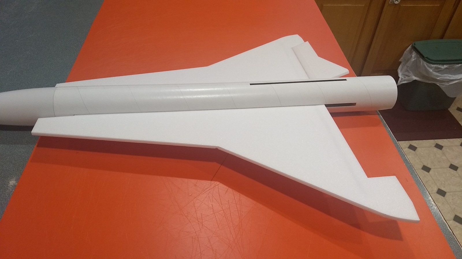
- Test fit then slide wing in place in slot, then slide the wing forward till it stops.
-
- Lay elevon into wing cutout with 1/16″ gap to outboard end and tape with blenderm keeping surface flat.
-
- Fold elevon over on top of wing and tape angled joint over the top and bottom of wing and test for movement.
-
- Center wing front and back and glue in place.
-
- Fold slot tabs back down and glue
-
- Glue vertical stab in place.
-
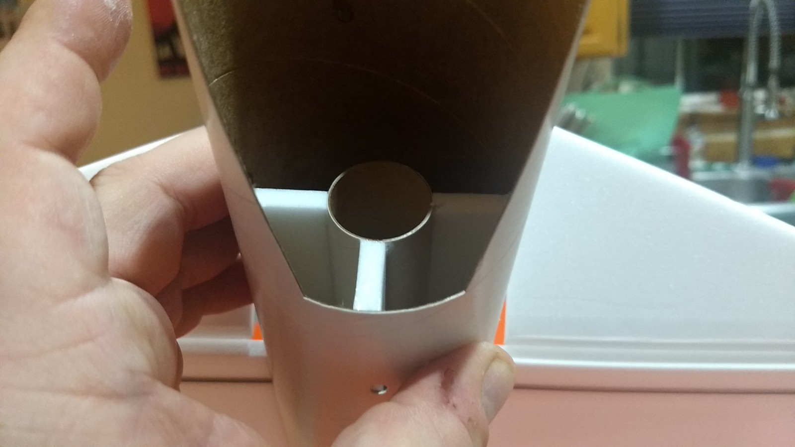
- Test fit and install motor mount till it stops against wing
-
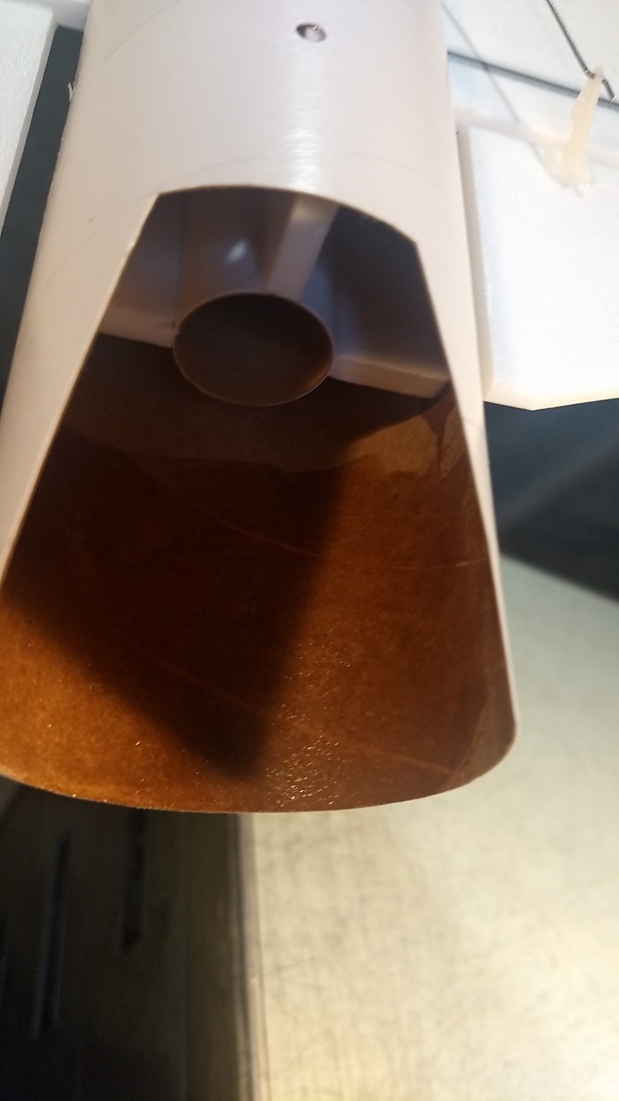
- coat inside top of body tube with CA to protect against motor exhaust.
-
- glue the two cockpit halves together.
-
- Showing v notchin cockpit that will help seal against nose cone.
-
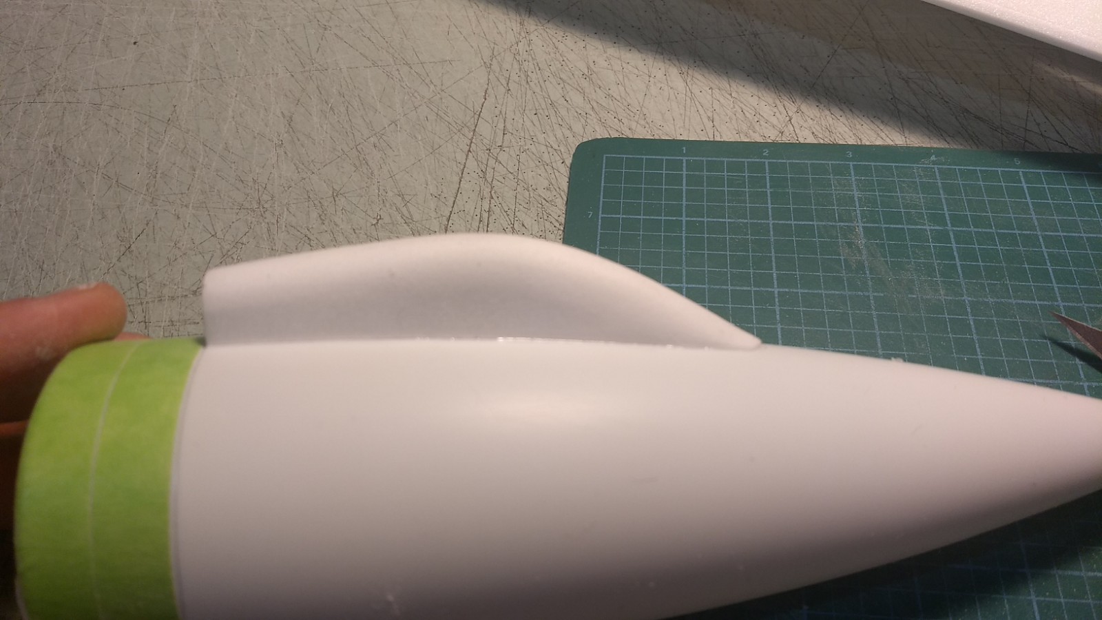
- Round cockpit then glue to nose cone so rear is even with the rear of the cone where the shoulder starts.
-
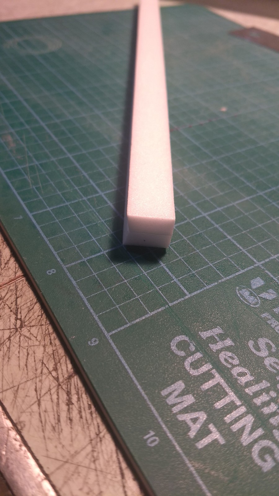
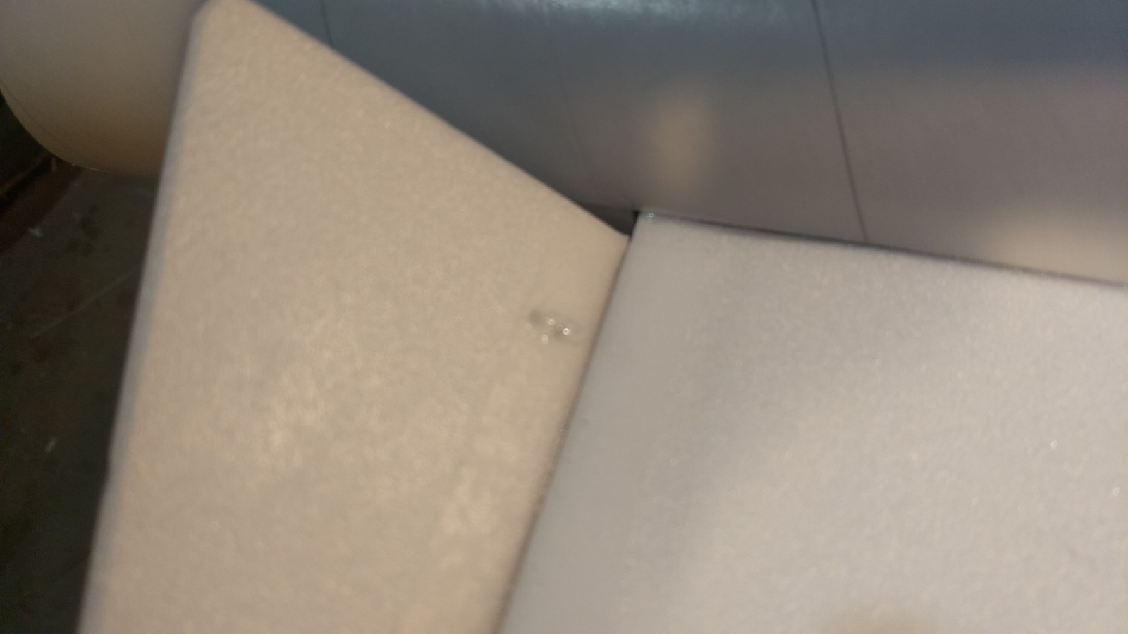
- Glue the spine halves together making sure angled surface make a V notch on the bottom. .
-
- conduit glued together.
-

- Round conduit
-
- Test fit and trim and glue conduit in place.
-
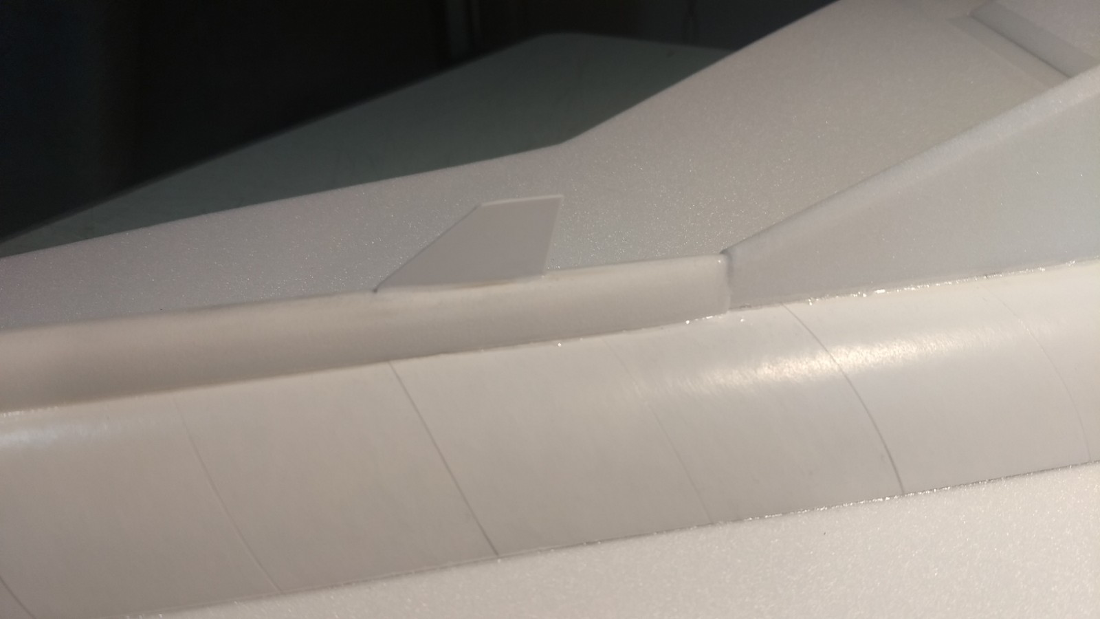
- Cut slot and install styrene ventral fin 1.25″ ahead of the vertical stab LE
-

- Install pushrods and horns, note pushrods are closest to the center of the model.
-
- apply glue to horn prongs to lock them in place.
-

- Attach servo and mark/cut pocked for servo.
-
- Fit servo lead into body, attach to receiver at the front and then glue servo in place keeping surface level.
-
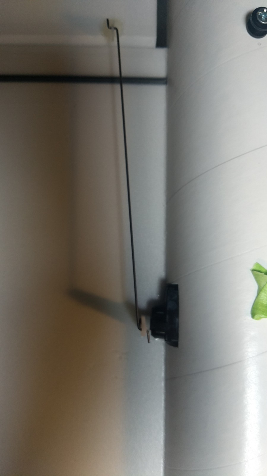
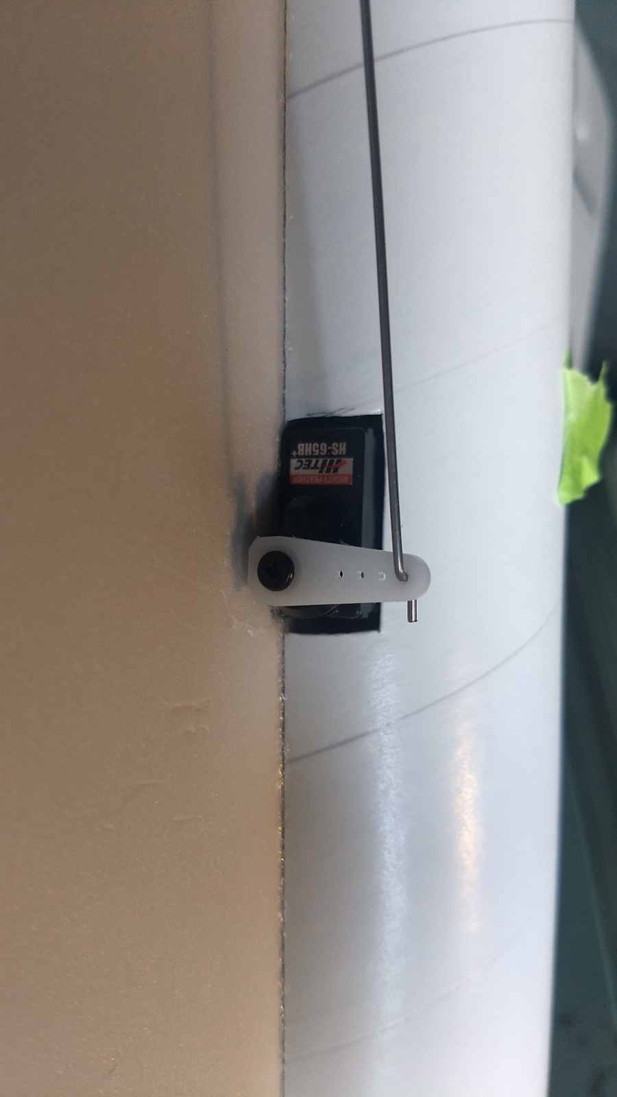
- view showing pushrod and servo installed.
-
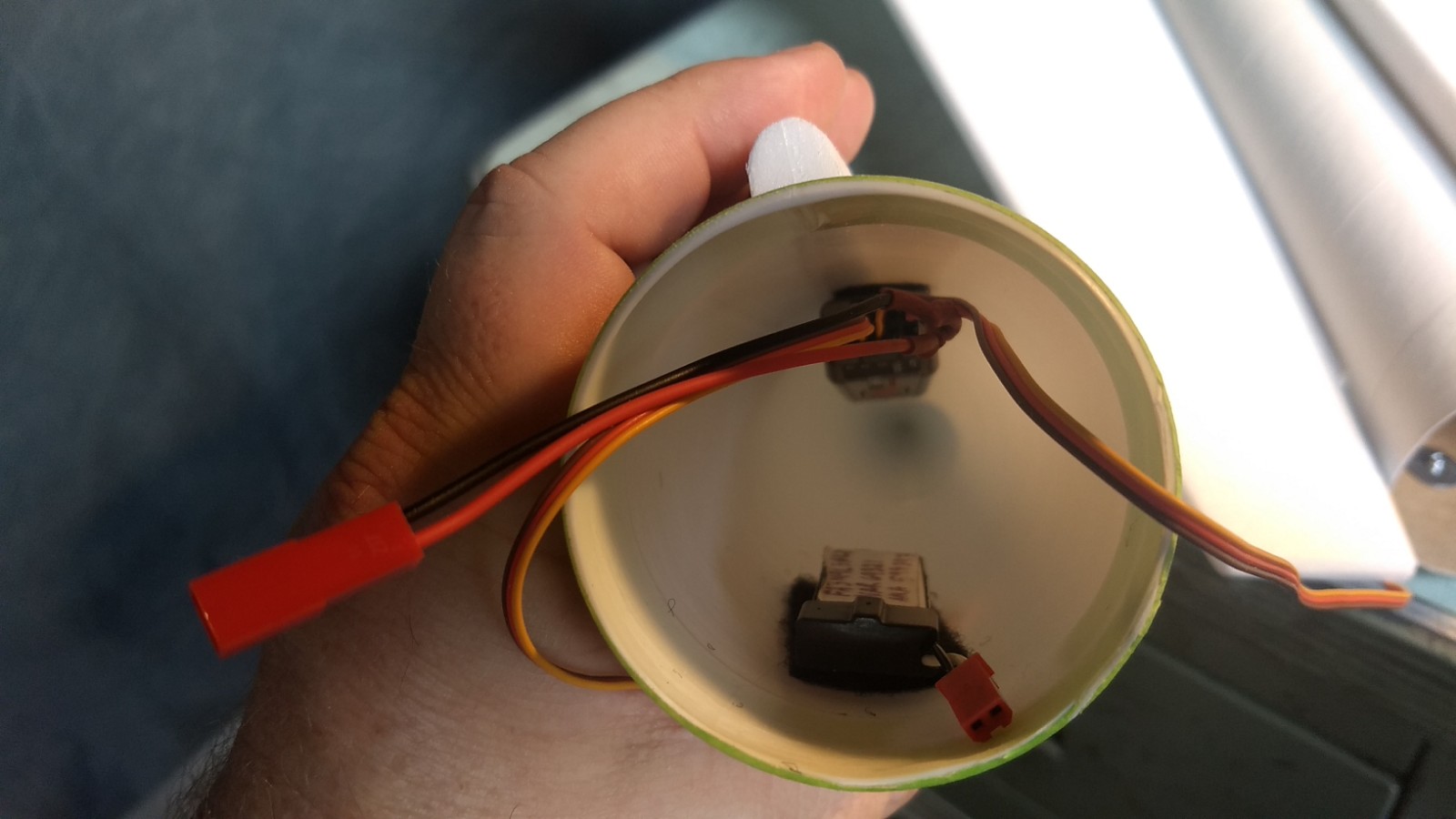
- Velcro receiver and battery in nose cone.
-
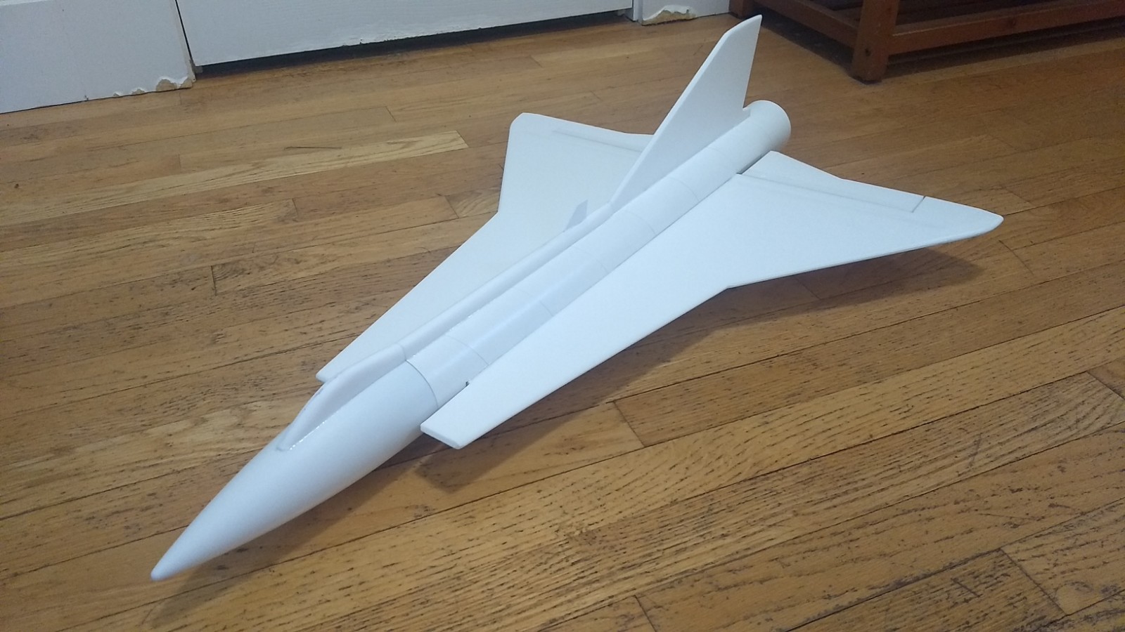
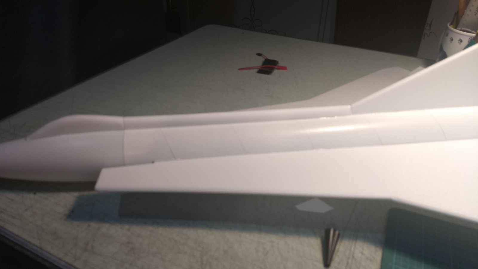
- Completed Airframe
-
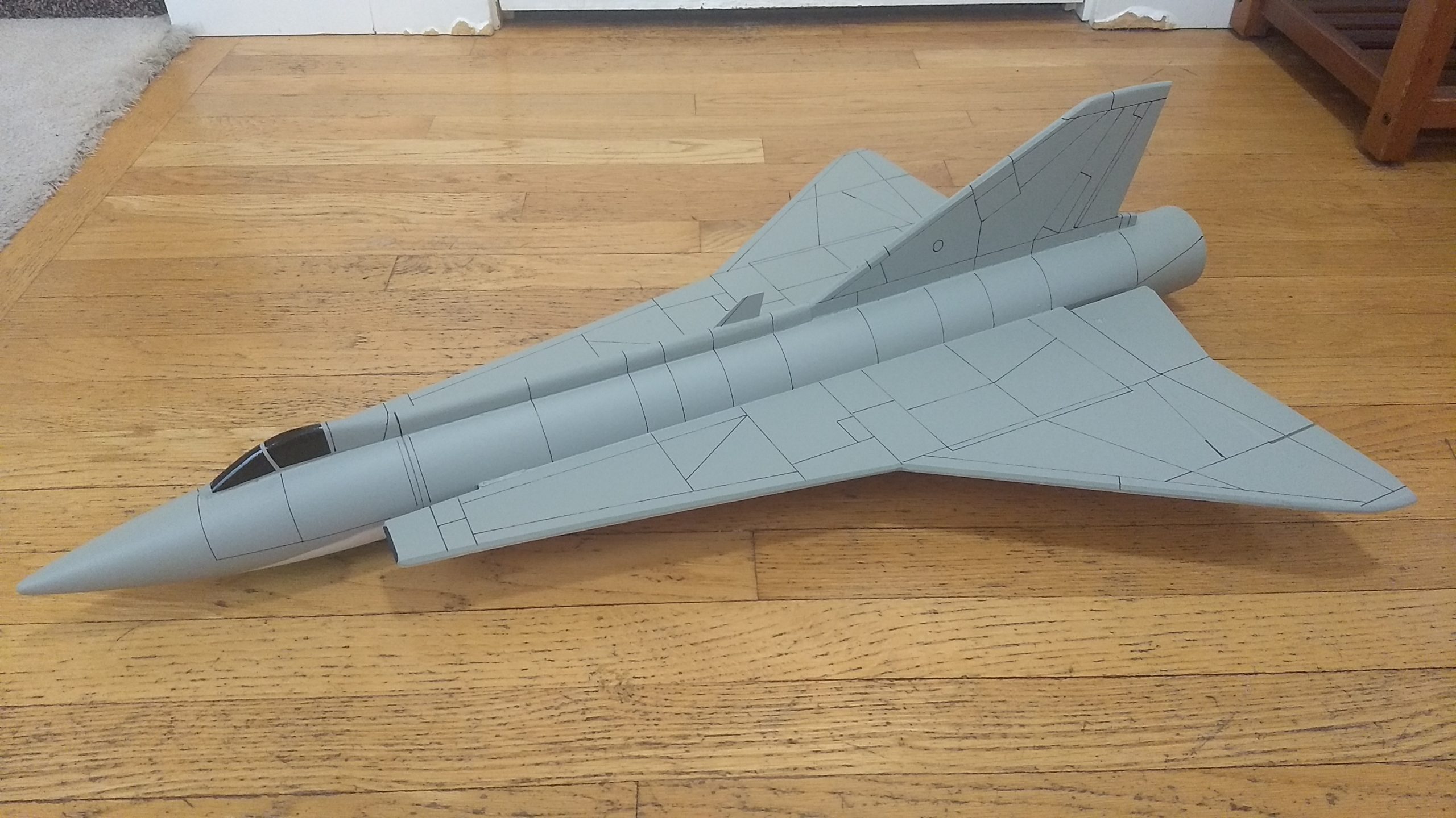
- Painted and panel lines applied
-
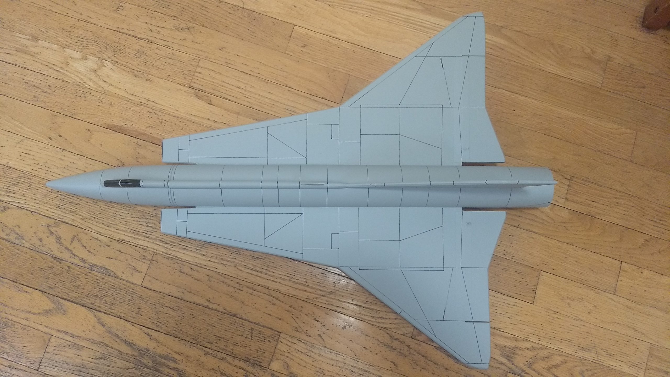
- Panel line top view
-
- completed model
-

- 3-view for panel line ideas
-
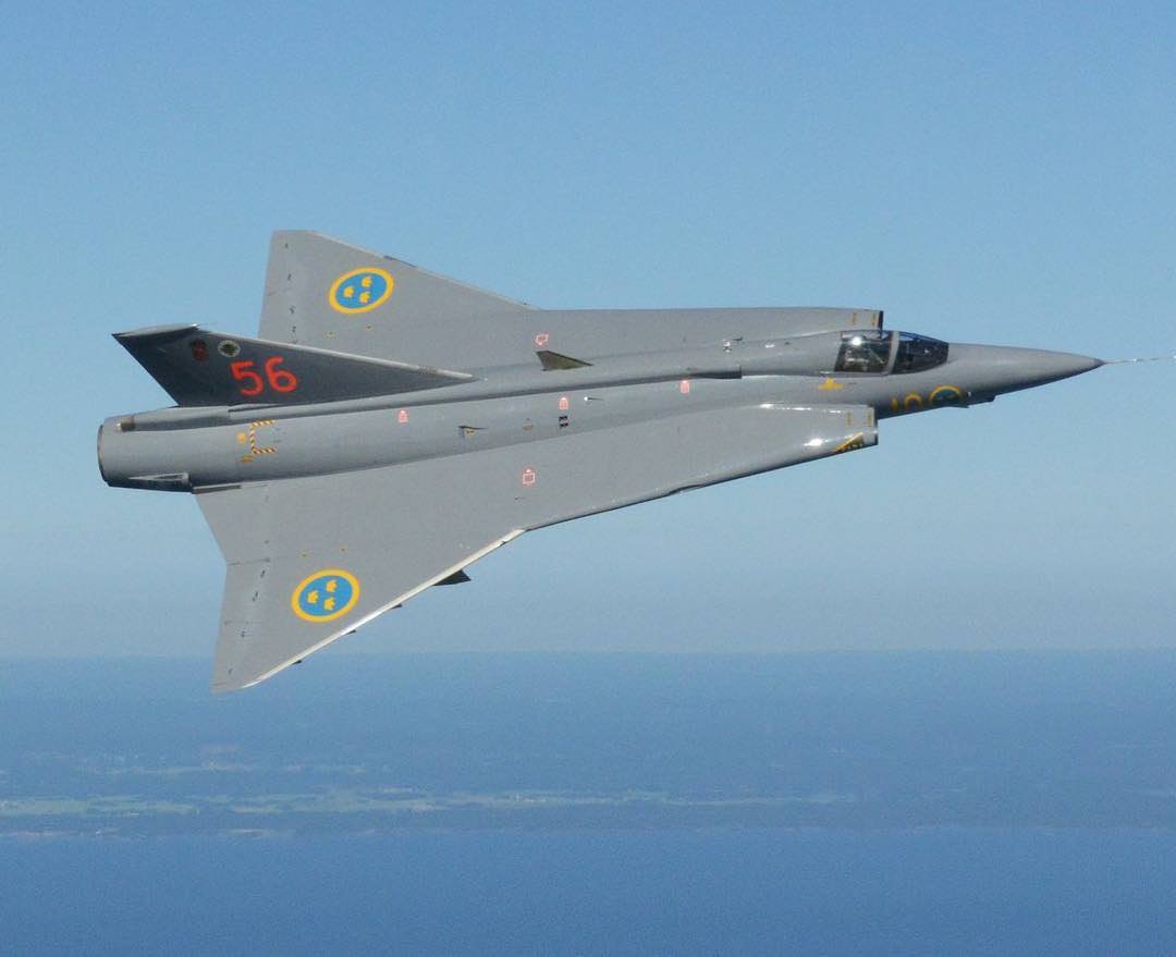
- Gray color scheme
-
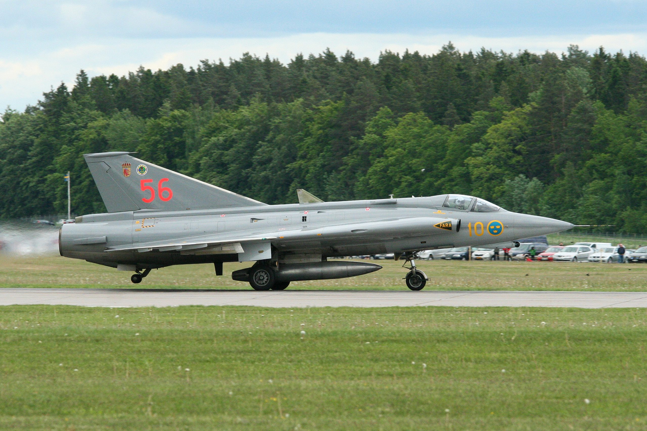
- Gray color scheme
-
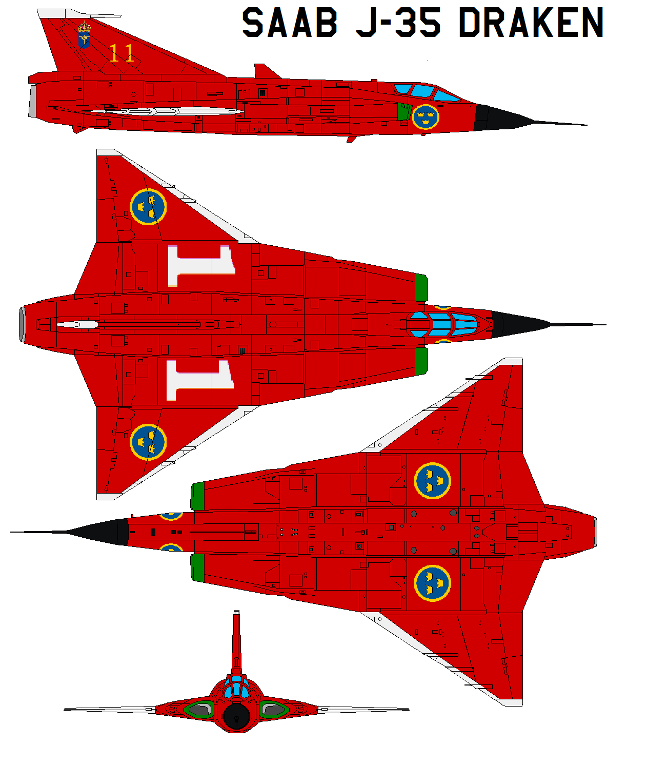
- Red Color scheme
-
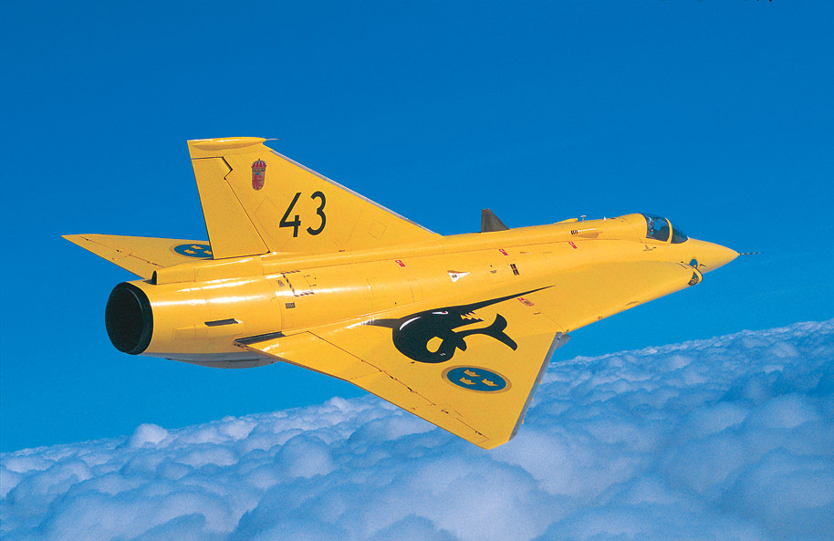
- Yellow Color scheme
-

- Example of stickershock decals.