The Delta Dart/Delta Dagger Instructions are identical as is setup, just the shape of the tail and Side intakes are different.
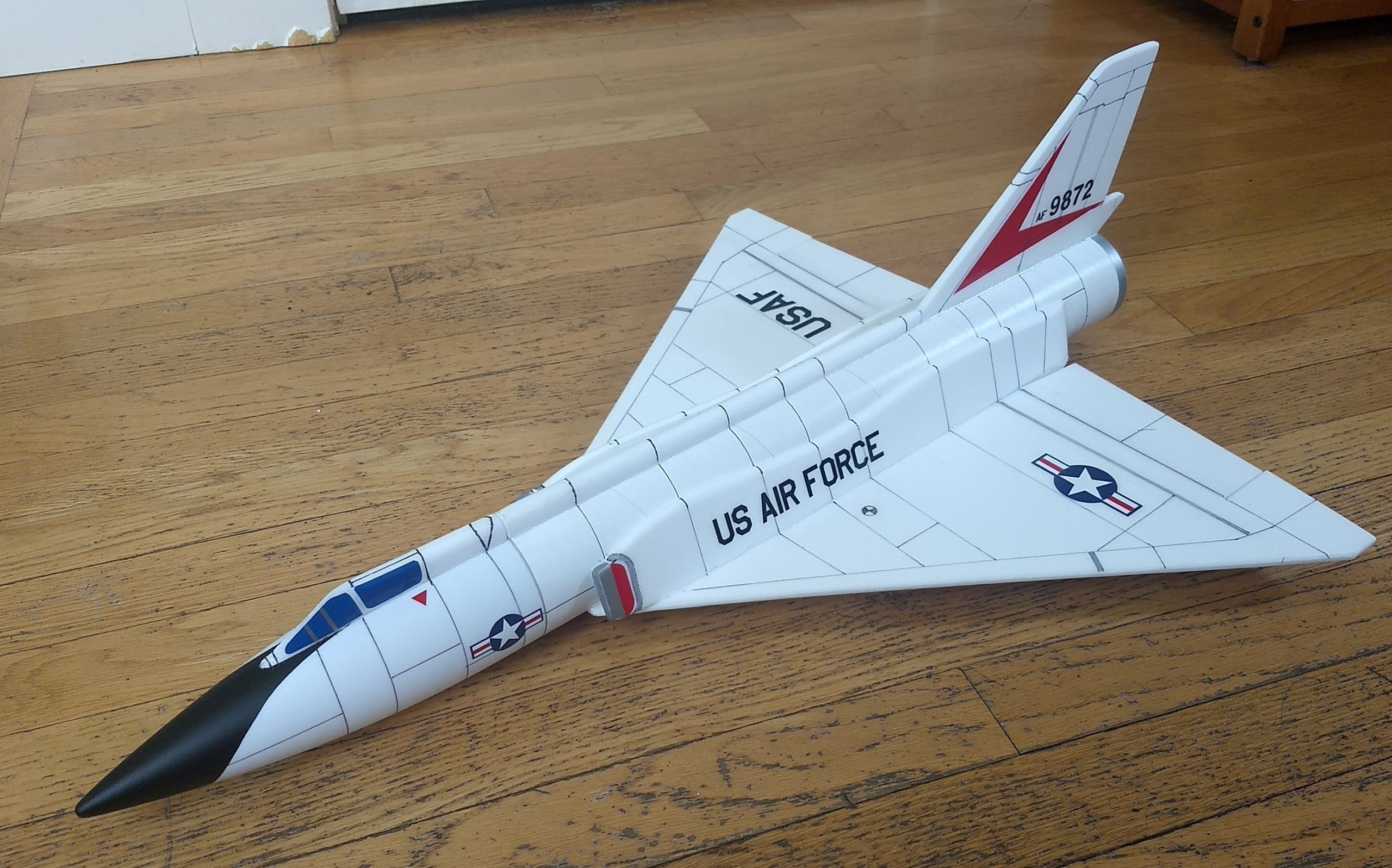
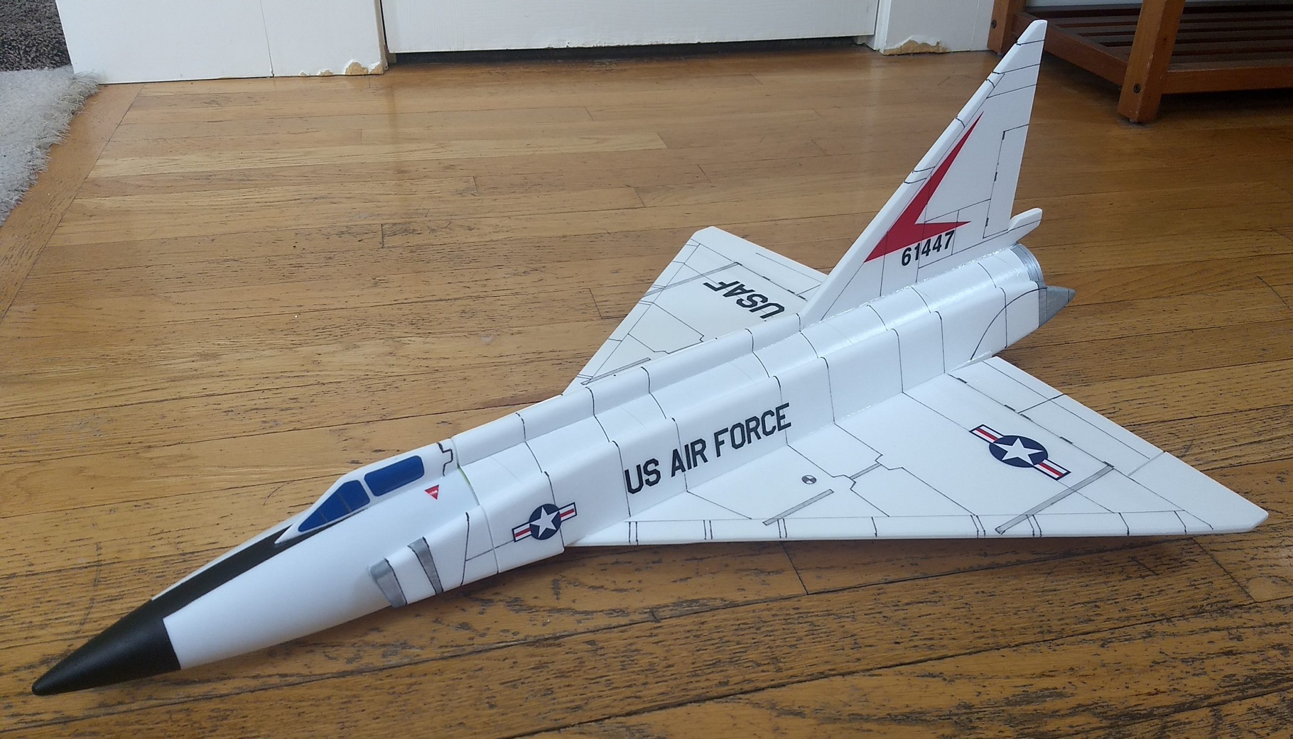
The Delta Dart RC Rocket glider kit is modeled after the Mach 2.4 Cold War Interceptor used by the USAF and Air National Guard Units into the 80’s. Length 27.5″, wingspan 20″, weight 8.35 oz (237 grams) rtf.
The Delta Dagger RC Rocket glider kit is modeled after our first supersonic interceptor and the first of the century series to enter service. Length 27.5″, wingspan 20″, weight 8.65 oz (246 grams)rtf.
Kits come with a plastic nose cone, 2.6″ white tubing for the body, 6mm depron wing and tail surface. Elevons are pre-hinged, rail button holes are pre-cut, spar slot is pre-cut and the body tube is pre-slotted for the tail and wing. Please refer to the General information for all kits tab above, then read these instructions completely before starting assembly.
Decals for the Delta Dart are available HERE:
Decals for the Delta Dagger are available HERE:
CG location for rocket flight ready to fly with motor and battery installed: 8 1/8” forward of the rear of the wing at the root.
Unpacking your kit:
The kits are packed to protect them in shipping, but the contents are fragile so unpack carefully. Carefully cut the tape holding the tubes in the box, then unwrap/lightly cut the plastic wrap to free the tubes, the spar may be packed in the tubes and the baggie with the little parts and nose cone will be in the tubes as well. Carefully cut the tape holding the cardboard wing protector in the box and carefully remove it, don’t pull hard or bend it. Then carefully cut the tape holding the cardboard top piece to the bottom. There may be some sticky tape holding the cardboard to the bottom cardboard piece, carefully peel it being sure not to bend anything. Once the top cardboard is free you can see the foam wing/tail parts, there are little fragile pieces in here, so unwrap carefully. It may be best to use an exacto to lightly cut the plastic wrap and carefully remove it without cutting into the foam. Make sure everything is free before you remove the pieces to avoid breaking anything. Kits contain one or two scrap pieces for repairs if you damage anything in construction or flight, just cut and patch in a spare piece of the foam if needed using foam safe CA+.
Welcome to the world of rocket boosted radio control gliders. This is not a model for a novice RC pilot, but anyone who is comfortable with RC flying of a medium speed model should be fine. Read through the instructions, look at the photos and be sure you understand the step before committing to cutting or glue.
Identify all pieces, the kit should contain:
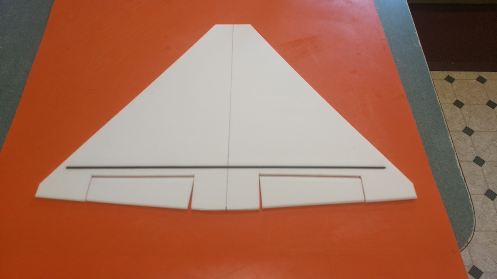
1 wing taped together
1 Nose Cone
1 vertical stabilizer
2 intake panels
2 foam conduit strips
2 canopy halves
1 wing spar
1 roll blenderm
2 control horns/Pushrods
1 Body Tube
Motor mount
2 13/16″ x 2.5″ wide strips to center the motor tube
Velcro(for battery and rx/bec attachment)
Lead weight
Notes before starting:
Foam safe CA+(Bob smith super gold + is good) is the only glue recommended for construction. You will also need foam safe accellerator to set the glue.
I now prefer to bevel the edges of the foam instead of sanding, it’s quicker, less messy and you don’t risk tearing the foam edge. I use a thin straight edge and cut a 1/16″ wide bevel on top and bottom of the surfaces. Before assembly you may bevel the leading and trailing edges of the wing, the leadin and trailing edges of the vertical stabilizer. For the intakes, cockpit and spine conduit, you may use 320 grit sandpaper and a sanding block to slightly round the edges of the foam, just go slow and do little bits at a time and use a light touch. Note for the conduit make a left and right version, look at the bottom edge it should be bevel cut so that the plate angles inward at the top, mark them right and left before you sand, then sand the upper edges round only on the outside edge and taper the rear surface to blend to the body tube, see pictures for clarity.
Assembly:
- Glue two 2.5″ long foam strips on the motor tube using foam safe CA+. These help center the motor tube in the body tube once you insert it into the body tube. Note the tabs will be on the sides of the tube, the fin tab will make contact on the top of the tube and the bottom will be touching or slightly above the wing at the front. Refer to the picture. If your kit came with a motor block glue this in the front of the motor tube at this time. The lines drawn on the motor tube are for reference but may not be perfectly aligned, use your eyeball to make sure they look as in the picture.
- Install the two rail buttons in the pre-cut holes at this time.
- Unfold the wing and glue the taped joint, then glue in the spar into the slot, once cured tape over the spar and center wing joint with the included blenderm tape.
- Test fit then glue the wing in the slot keeping the front and rear centered.
- Test fit then glue on the two intake plates, they should be even with the end of the wing and not interfere with the elevon, they should angle inward, if the bottom edge is not beveled, cut a slight bevel with a straight edge and exacto. Glue the bottom edge, then when set apply glue to the top edge to hold it, you don’t need a lot of glue it’s just for looks. (**If you are building a Delta Dagger the side plates and shape is different, The intake is notched to fit over the front and rear of the wing to locate it in place. When done gluing the intakes to the body tube glue them to the nose cone making sure not to glue the cone in place. When done, slice the intake on both sides with an exacto to allow the cone to be removed for replacing the flight battery.)
- Glue the vertical fin into place. Make sure the vertical fin is straight up and down using a triangle or something similar. Apply a light filet to both sides of the vertical stab on the inside and outside of the body tube.
- Test fit the motor mount into the body tube and under the fin tab. Make sure it fits, or sand the foam tabs lightly. Glue the motor tube in place, it will inset about 1/2″ from the end of the body tube. Put a fillet on each side of the motor mount tabs and fuselage. The motor tube may just touch the wing or have a gap, to make sure the motor tube makes full contact with the fin tab you can cut a piece of scrap foam to fit under the front of the motor tube to help make sure it makes contact with the fin tab.
- Glue the two canopy halves together, note they have a v notch cut in the bottom to make fitting easier.
- Glue the two conduit halves together, they also should have a v notch cut in each half to make fitting easier.
- Sand the conduit round on top
- Sand the canopy to a bevel on the leading edge and round on the rest of the top, see pictures for clarity.
- Glue the canopy to the nose cone, the rear of the canopy should be even with the rear of the nose cone when it is inserted into the body tube.
- Fit the conduit so that it butts against the vertical stab, you will need to sand the rear to a taper to match the thickness of the stab, and trim the rear so the front butts against the cockpit when the nose cone is in place, glue the conduit in place.
- Apply CA+ to one of the control horns and press it in place on the BOTTOM of the control surface in the pre-made holes. Note The control horn holes face forward and the pushrod should be closest to center of the wing. Repeat for the other side. Apply a fillet around the control horn on the the prongs on the top of the wing to lock them in place. See photos.
The basic construction is now complete.
Radio Installation
Note: Your radio needs to be configured for Delta mixing, this means that the servo arms will move the same direction during elevator stick movement and opposite for aileron stick movement. Connect your servos to the receiver one in the aileron connection and one on the elevator connection and apply power. Use a servo arm at least 9/16” long and with holes small enough that there won’t be slop with the pushrod wire when installed. I use the hole furthest out on the servo arm, to maximize movement. On some servos there are a long two-ended servo arm, you can trim off one end and use that arm to get sufficient length. Zero out any trim settings on the transmitter.
- Flip the model upside down. Connect each servo to a pushrod. If the pushrod is too tight, you can use twist an X-Acto knife in the servo arm hole to make it larger, but be careful and do not make it too large. Each servo should be on the bottom of the wing, with the servo electrical wire pointing forward and the servo arm pointing toward the wing tip. Tape each servo in place so that the control surfaces are centered and the pushrod is perpendicular to the control surface hinge joint, the servo will be in the middle of the wing. With the model right side up look at it from the rear. Moving the transmitter stick back(up elevator) should move both elevons up. Moving the transmitter stick to the right should move the right elevon up and the left elevon down. If you can’t get the servo reversing to give you the right polarity try swapping aileron/elevator inputs to the receiver or turning the servos over and swapping the servo arms to the other side of the output shaft. If that is correct, continue.
- I then measured where the servos would meet in the center of the model and cut out the body tube to fit the servos so that they were touching in the middle and the control surfaces were flat. I bend the pushrods by hand, so it is very hard to make them exactly the same. For this reason the cutout may need to be slightly oversized so that both servos can fit and have the control surfaces level. If you need to bend the Z bend slightly to get things to line up that’s perfectly fine.
- I then cut a slot into the middle of the wing in the servo cutout, passed the receiver into the cutout and forward to the front of the model. If your servo wires are very short you may need to add extensions. I used velcro included to attach the receiver right at the front of the top of the wing inside the model. The battery is held in the bottom of the nose cone inset about 1/2″. My leads were just long enough to do this, but I had to use a forceps to grab it and put it in place, short 6″ extensions add a bit of weight but will make this much easier to do:) In that case you could just cut a small notch in the wing, and pass the wires and exensions forward and then attach to the receiver.
- Glue the servos in place. With the radio still on, put a moderate amount of glue on the servo, being careful not to get any near the output shaft, and set it in place on the wing keeping the control surface centered. Do the same to the other side. Apply a fillet of glue around the servo/wing to help secure it and let it cure being careful not to get any glue near the output shaft of the servo.
- Make sure the control surfaces are centered, use trims if needed. Now measure the control surface movement. Full elevator movement should be 1/2 to 5/8″ in each direction, aileron movement should be 3/8″ in either direction. I used a rate of 65% for aileron and 100% for elevator using the outermost hole in the hs-65HB dual arm horn.
- If you have a flap/elevator mix you can program up elevator trim for boost and glide. If you can’t set the up elevator trim to a switch on your radio you’ll have to manually put in boost and glide trim using the trim tabs which is hard to do while flying the model. My model needed approximately 1/4-5/16″ of up trim for glide. My particular model needed just a small amount of down trim for boost, I used down 5 for boost and up 32 for glide on my dx-8 gen2 settings.
- If you decide to paint your model, I can only recommend testors/model master enamel spray at this time, others I’ve tried damage the foam surface. I recommend flat colors as they dry faster and the surface imperfections of foam aren’t as noticable. Paint typically adds 1/2 to 3/4 oz. On this model I just painted the nose cone with testors flat black after masking.
- You can use a black fine line sharpie to add panel lines or rivet detal if desired. I also used a small amount of silver sharpie for accents in a few places(on the side plates for example)
- If you choose to use the stickershock markings, after application use a hair dryer on hot to warm the markings and them push them down into the foam surface with your finger. They will really conform and stick down well.
- Install your battery.
- Insert your heaviest loaded rocket motor into the motor mount
- Support the model upside down at the balance point indicated for boost. Glue supplied lead weight in the nose or tail as needed to balance it. Do not use all of the lead, just as much as needed. Do not try to fly the model too nose or tail heavy. Remember, a nose heavy model flies poorly, a tail heavy model flies once.
Flying: See the General Instruction link at the top for flying instructions. Be ready on the first few flights to keep the model straight till you have the trims set perfectly for boost and glide.
-
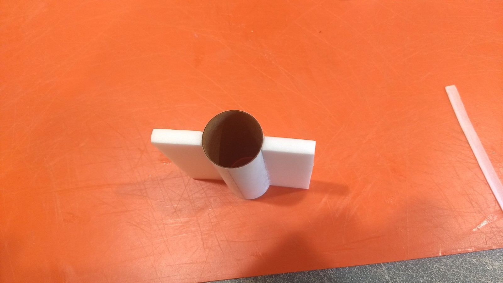
- Glue centering strips on motor mount
-
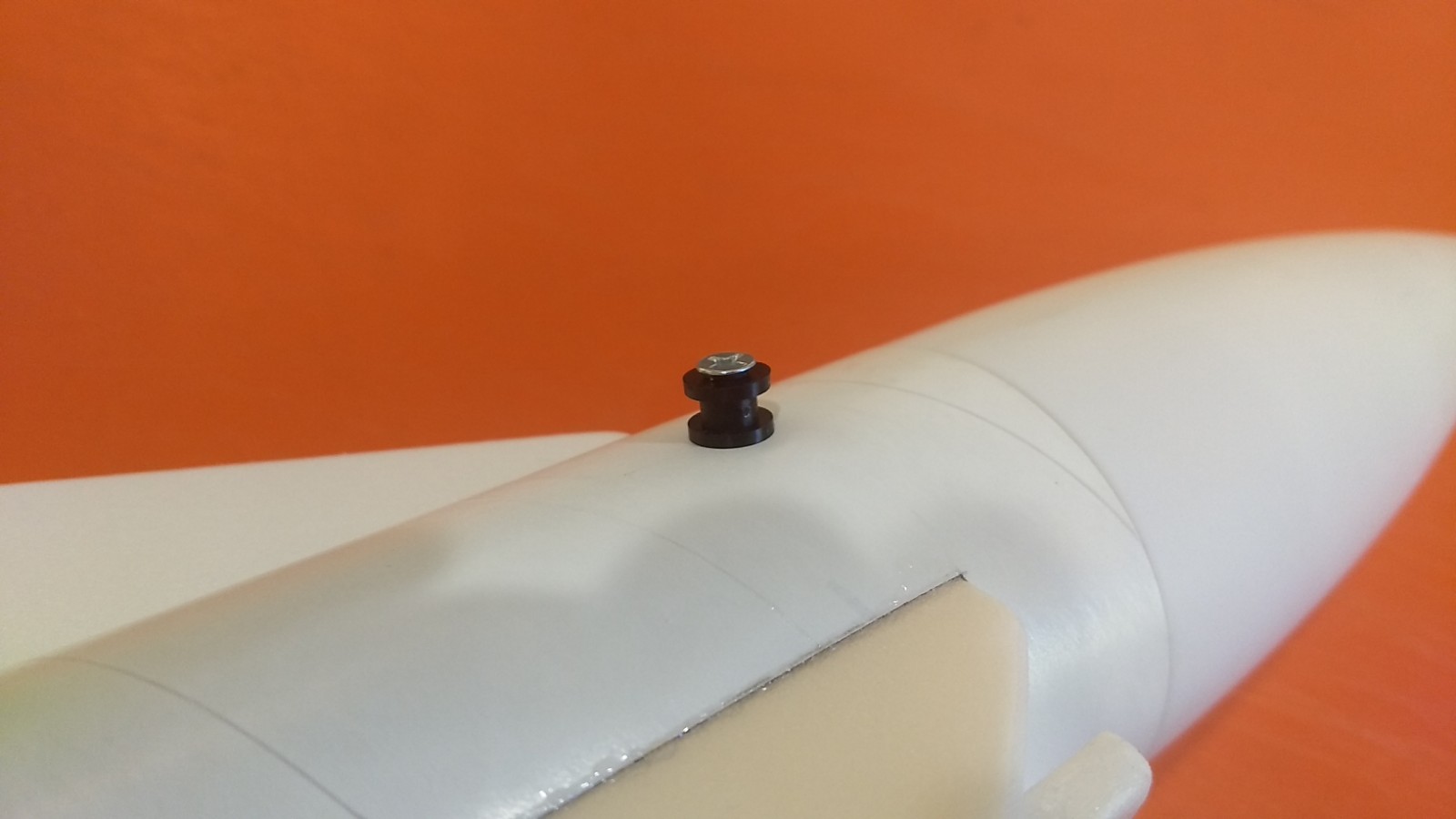
- Install Rail buttons
-
- Glue wing joint and install spar and tape over spar and joint.
-
- Test fit wing in slot and glue when centered.
-
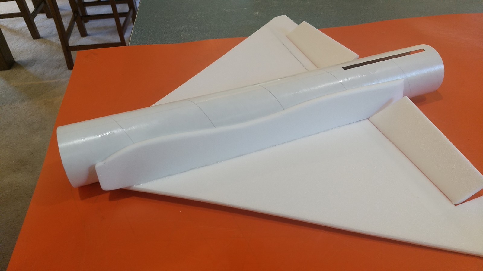
- Glue the two intake plates, note there is a right and left, the bottom should be bevel cut to angle the plate inward toward the model. The rear should be even with the rear of the wing and not interfere with the elevon.
-
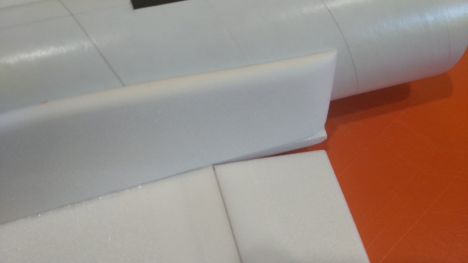
- Rear of the intake plate.
-
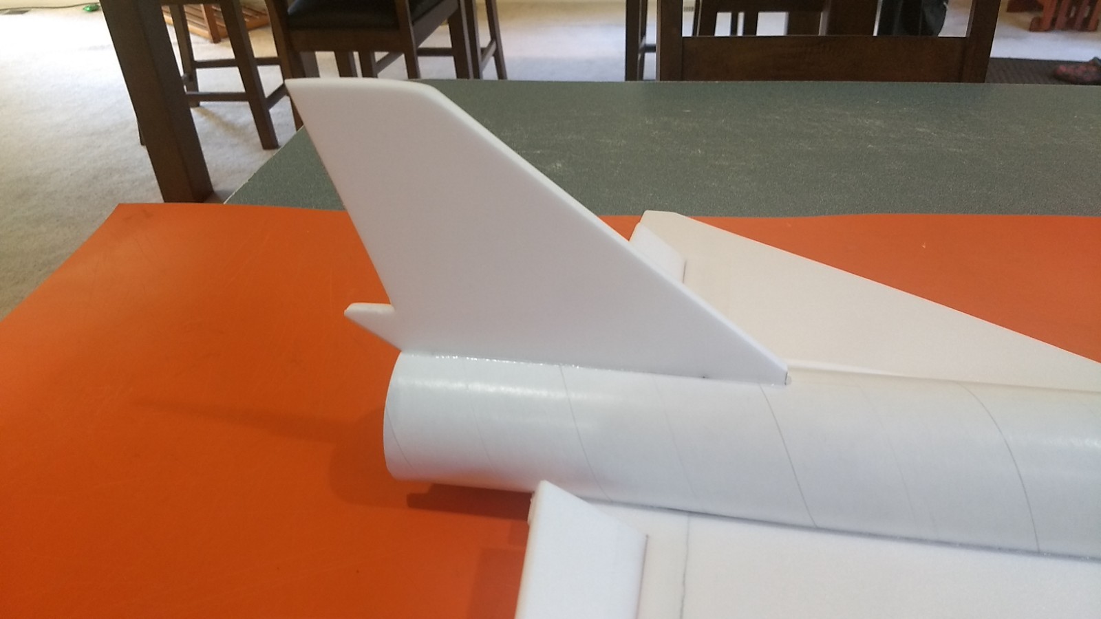
- Install the Vertical Stab.
-
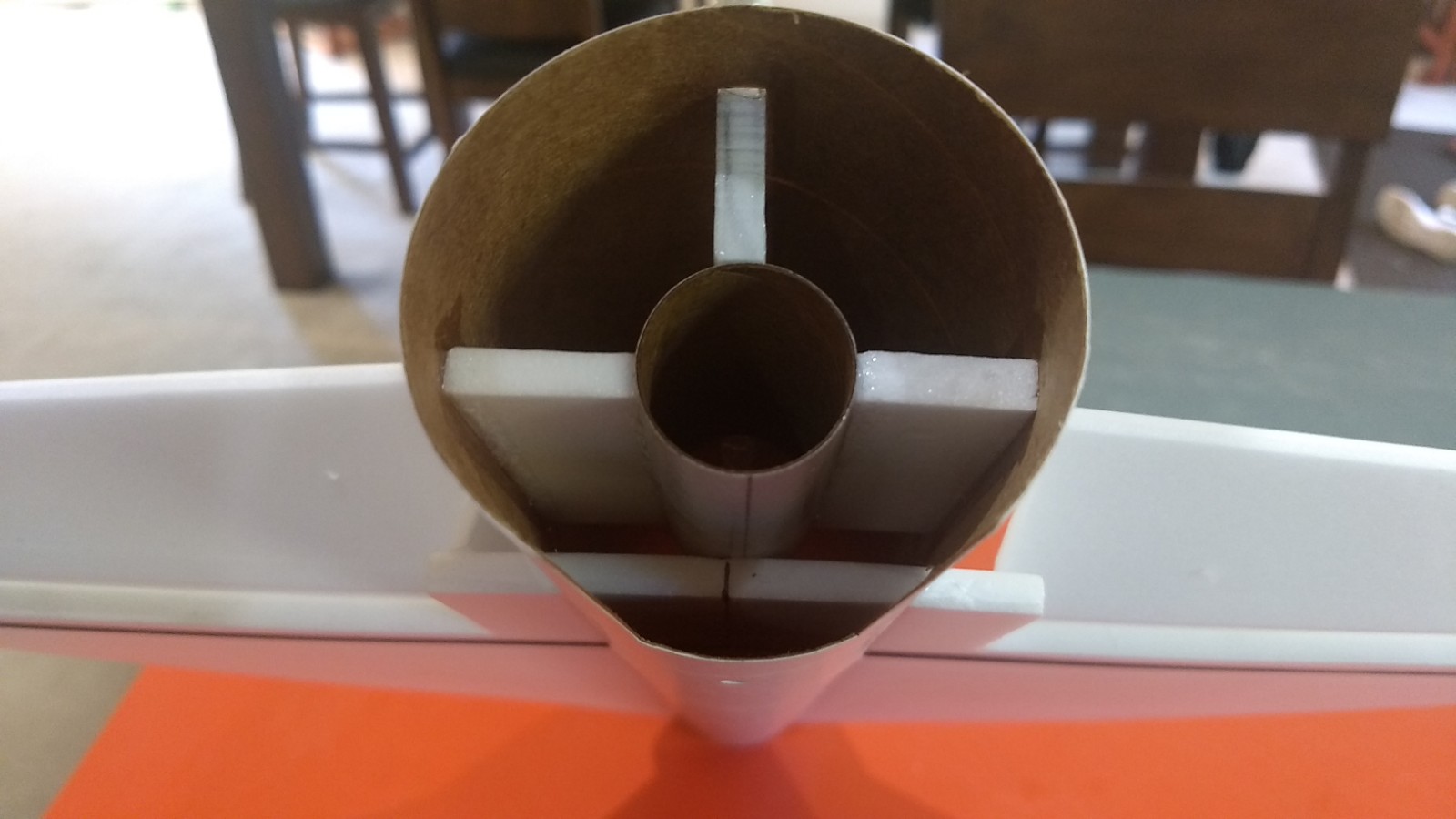
- Test fit then glue in the motor mount.
-

- If you have a gap between the motor tube and the wing……
-
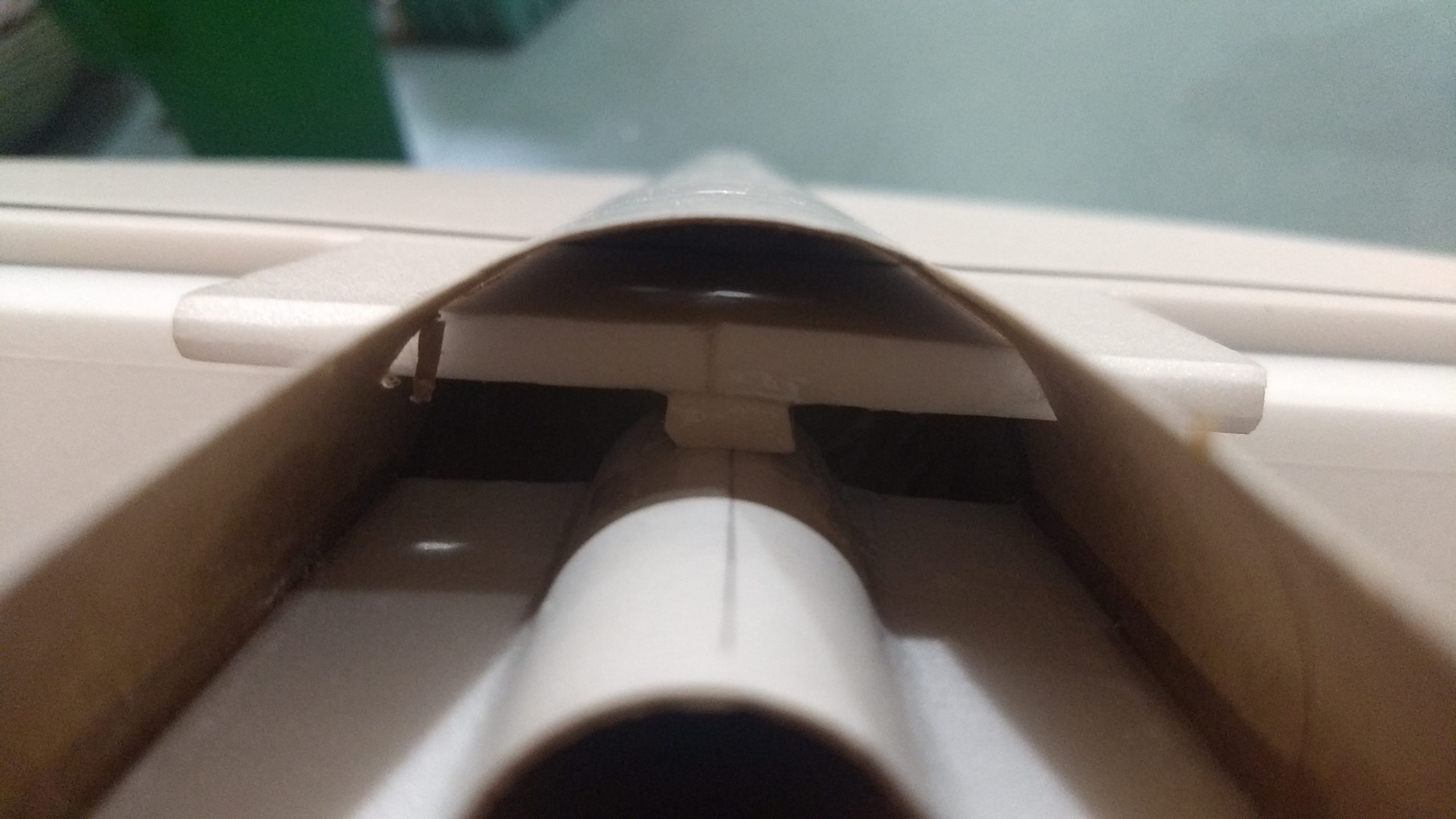
- You can glue a piece of scrap between the wing and motor tube to fill the gap and make sure the motor tube makes full contact with the fin tab.
-
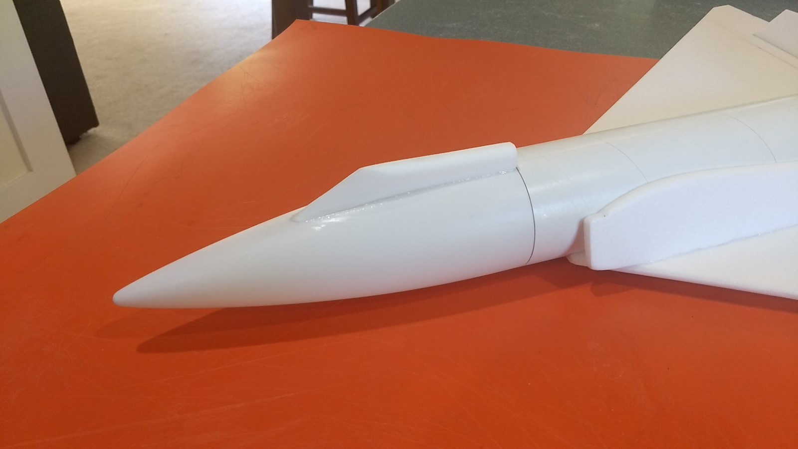
- Join the two cockpit halves and sand to shape, fit to the nose cone with sandpaper and glue in place.
-

- Join the two conduit halves, shape then fit and glue on the body tube top, this completes assembly.
-
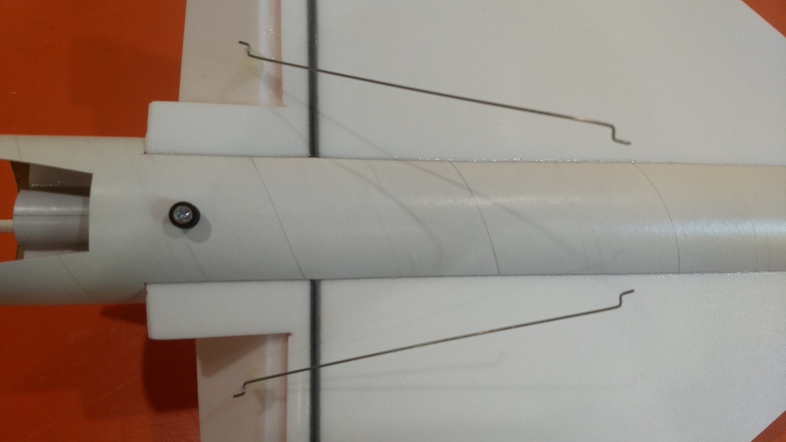
- Glue the two pushrods, note they are angled inward toward the center of the model.
-
- apply glue to the tops of the control horn prongs to lock them in place.
-
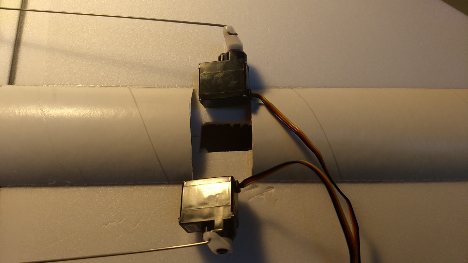
- Cut out for the servos and make a hole in the middle of the wing for the receiver.
-
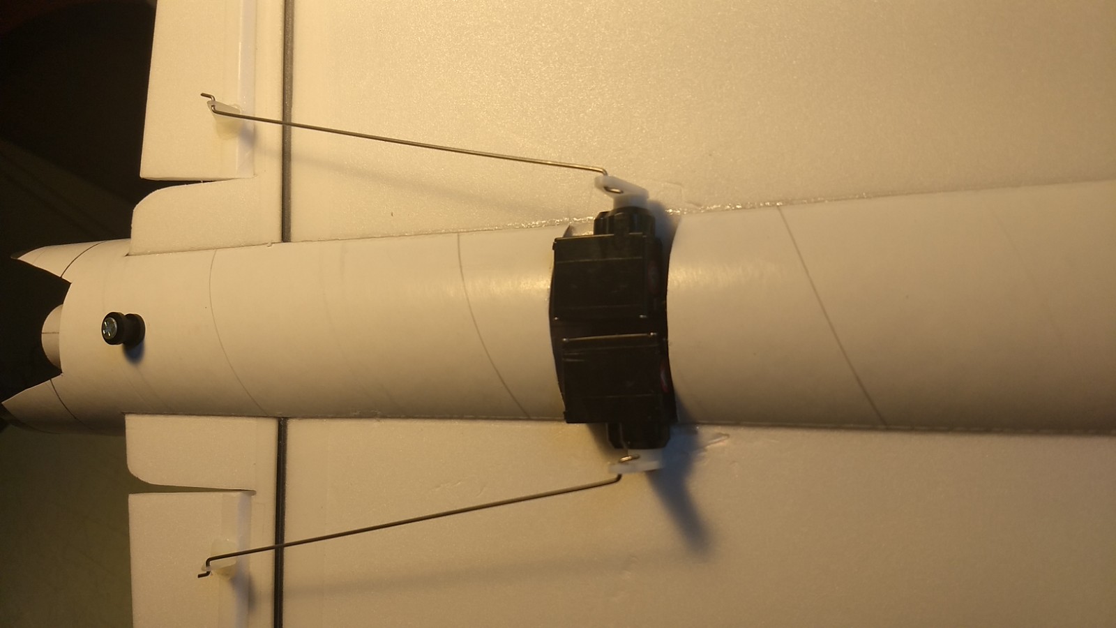
- Pass the receiver in and forward and then glue the servos in place keeping the elevons aligned.
-
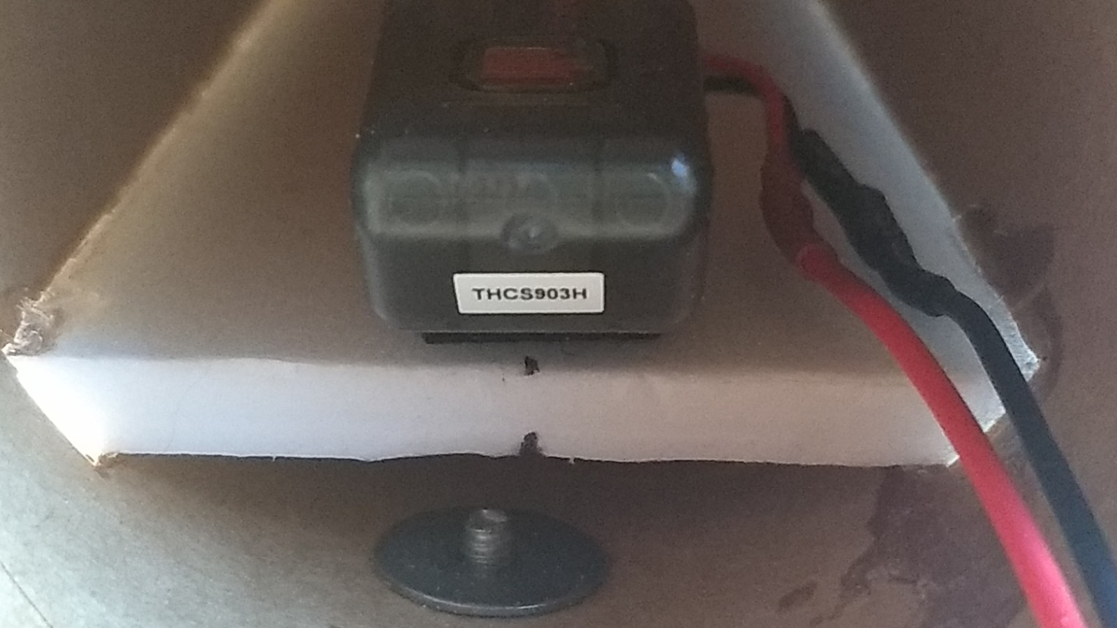
- Velcro the receiver to the top inside of the wing.
-
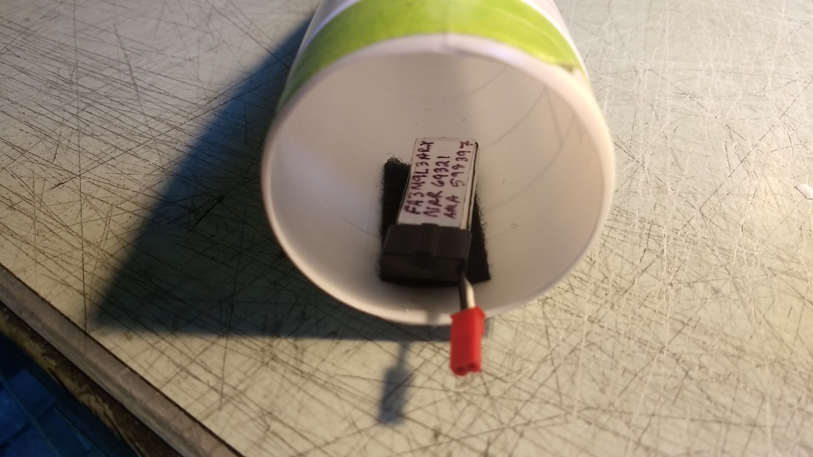
- Use remaining velcro to attach the flight battery.
-
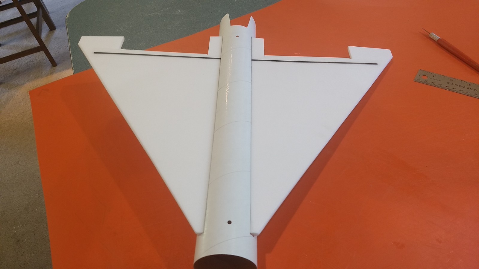
- Completed F-106 Delta Dart
-
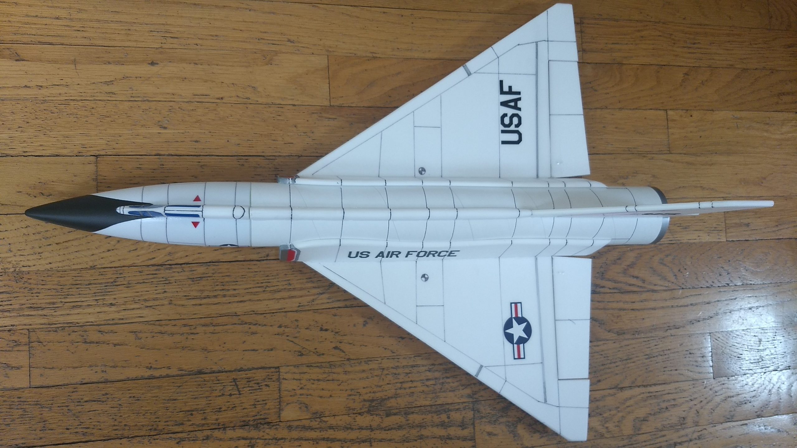
- Delta Dart top view
-
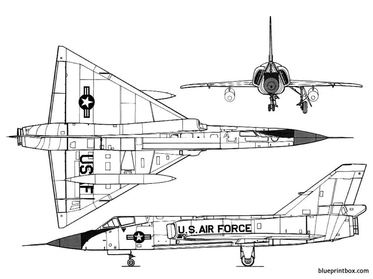
- 3-view
-
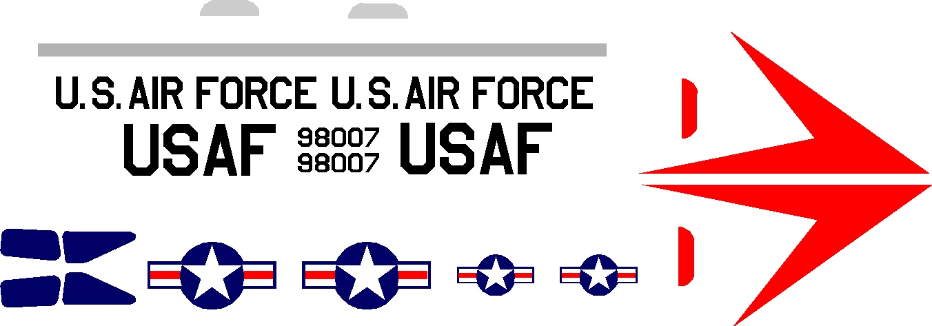
- Example of Stickershock Delta Dart Decals.
-
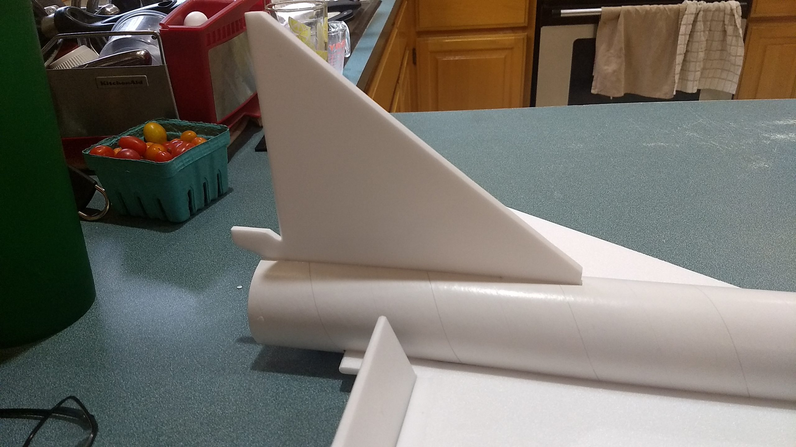
- Delta Dagger tail installed
-
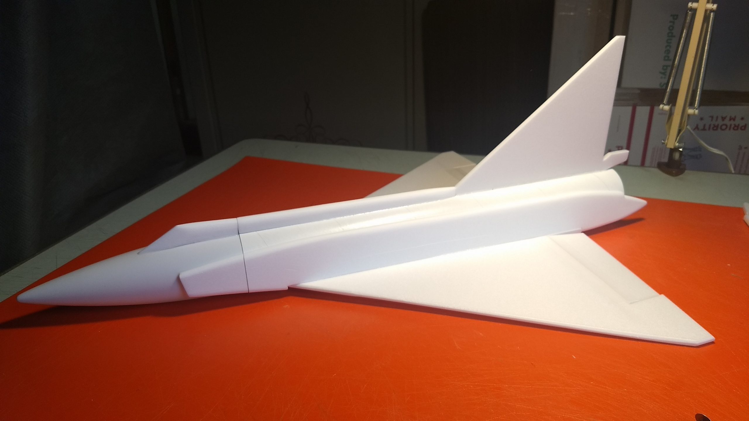
- Delta Dagger side intake plates installed, cockpit and conduit fit and glued and airframe completed ready for radio install.
-
- Completed F-102 Delta Dagger
-
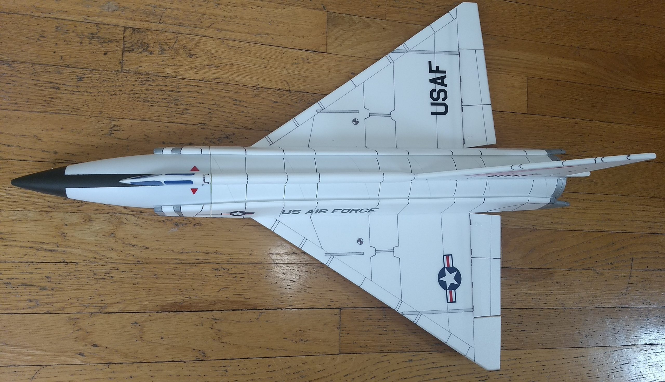
- Delta Dagger top view
-

- Delta Dagger 3-view
-
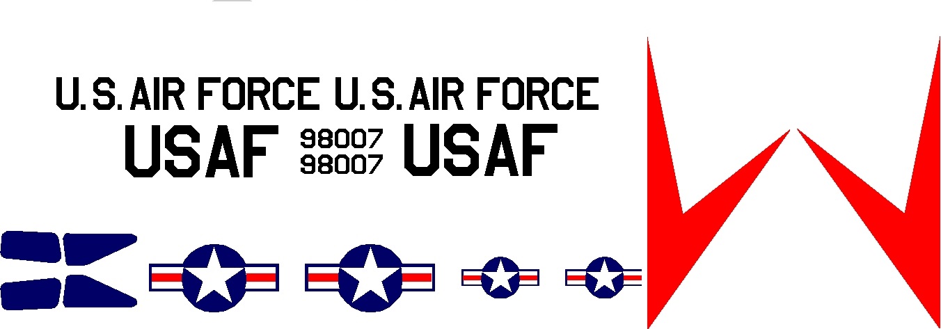
- Example of stickershock Delta Dagger Decals
-
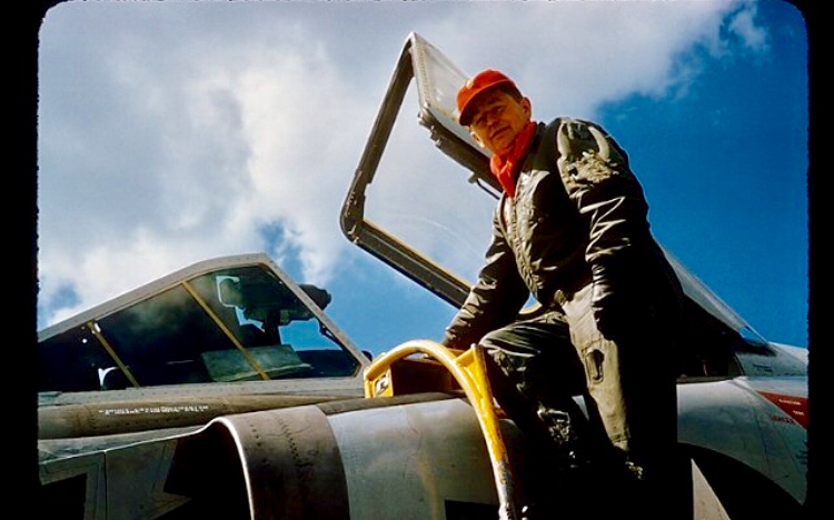
- Pictures sent to me by Je Thompson who’s uncle flew them in Texas
-
- Pictures sent to me by Je Thompson who’s uncle flew them in Texas
-
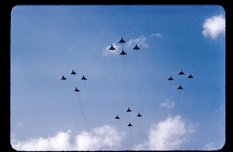
- Pictures sent to me by Je Thompson who’s uncle flew them in Texas
-
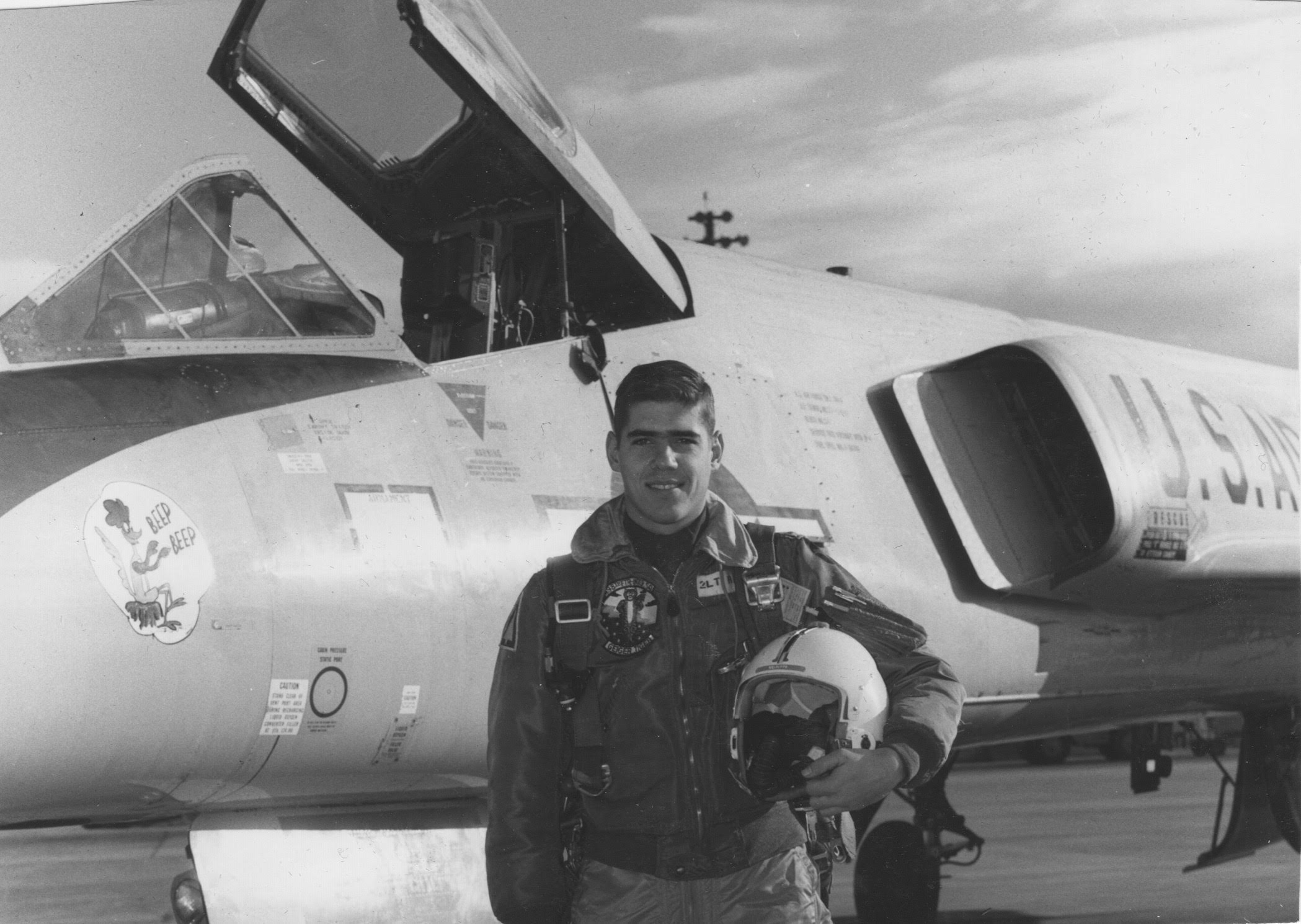
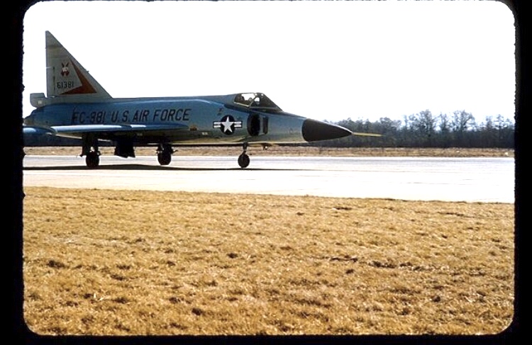
- Photo of one of my customers who’s dad flew the F-106