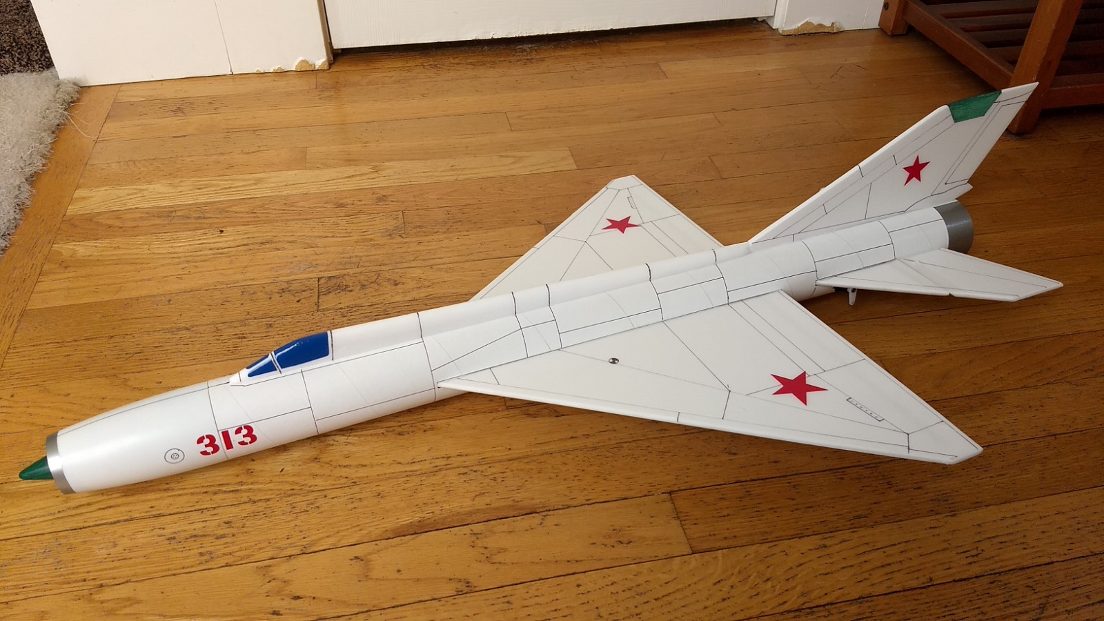
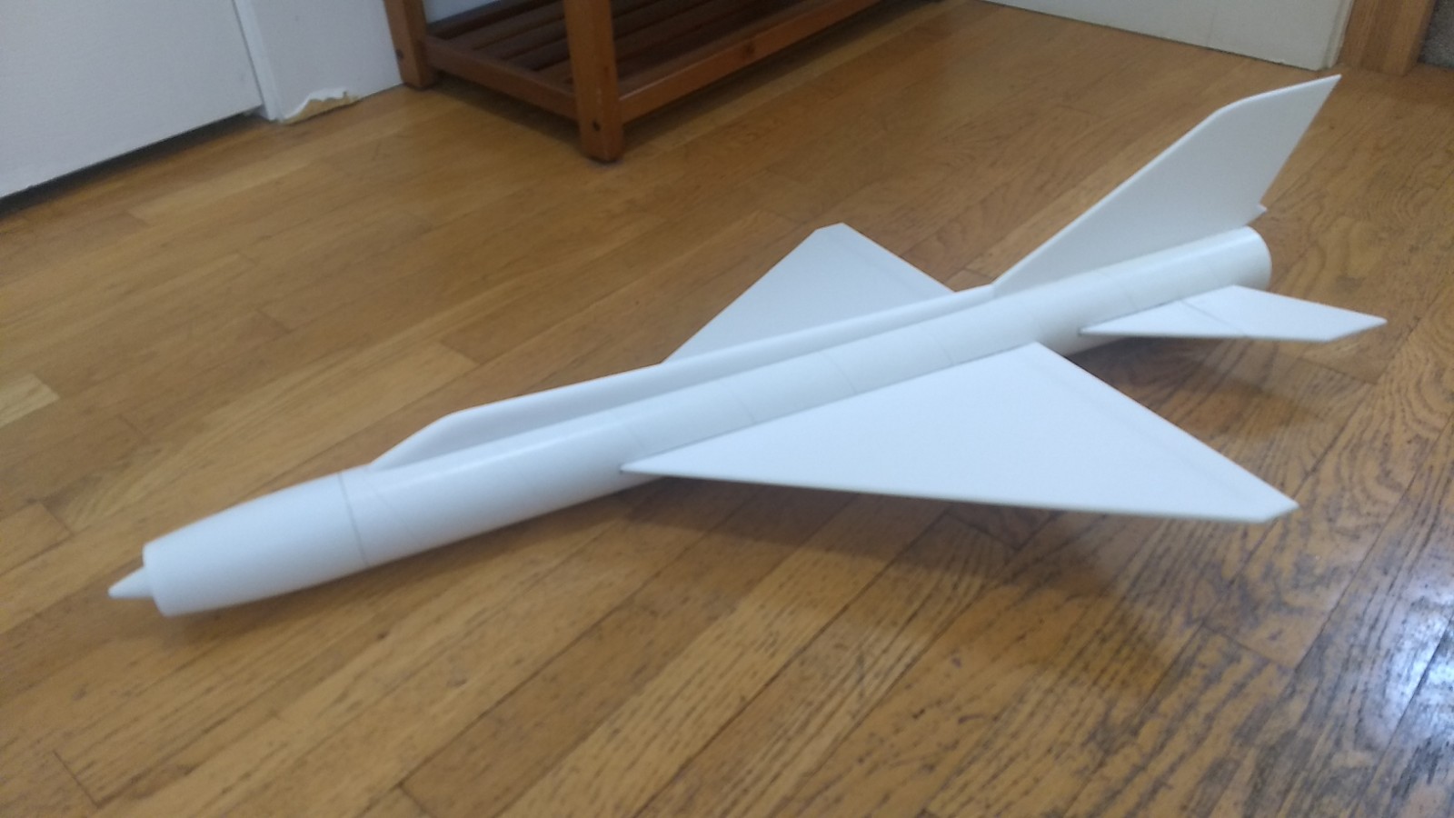
The Mig-21 RC Rocket glider kit is based on the Mach 2 aircraft which is one of the most prolific soviet jet fighter aircraft of all time. It features a mid mounted depron wing with spar installed, 2.6″ white tubing for the body pre-slotted for the wing and tail and depron tail surfaces with elevons pre-hinged. Rail buttons holes are are pre-punched and the white plastic nose cone is pre-cut. Specs: 37″ length, 22″ wingspan, 10.5 oz rtf, for 24mm E-6 single use or reloadable motors.
CG location for rocket flight with battery and loaded motor installed 7 5/8″ forward from the trailing edge of the wing:
Please refer to the General Information Link above then read the instructions completely before starting assembly. The assembly photos are for general reference but may not include every step in the instructions. If you want hardcopy to work from, all you have to do is click/drag/select and copy all of the text below, open word and paste with “keep original format” and it looks exactly like it does online then you can print it.
If you want to order the decals from sticker shock you can order them HERE
Unpacking your kit:
The kits are packed to protect them in shipping, but the contents are fragile so unpack carefully. Carefully cut the tape holding the tubes in the box, then unwrap/lightly cut the plastic wrap to free the tubes, the spar may be packed in the tubes and the baggie with the little parts and nose cone will be in the tubes as well. Carefully cut the tape holding the cardboard wing protector in the box and carefully remove it, don’t pull hard or bend it. Then carefully cut the tape holding the cardboard top piece to the bottom. There may be some sticky tape holding the cardboard to the bottom cardboard piece, carefully peel it being sure not to bend anything. Once the top cardboard is free you can see the foam wing/tail parts, there are little fragile pieces in here, so unwrap carefully. It may be best to use an exacto to lightly cut the plastic wrap and carefully remove it without cutting into the foam. Make sure everything is free before you remove the pieces to avoid breaking anything. Kits contain one or two scrap pieces for repairs if you damage anything in construction or flight, just cut and patch in a spare piece of the foam if needed using foam safe CA+.
Welcome to the world of rocket boosted radio control gliders. This is not a model for a novice RC pilot, but anyone who is comfortable with RC flying of a medium speed model should be fine. Read through the instructions, look at the photos and be sure you understand the step before commiting to cutting or glue.
Mig-21 Rocket glider instructions
Identify all pieces, the kit should contain:
1 wing taped together
1 Nose Cone
1 vertical stabilizer
2 control horns w/pushrods
4 2.75″ long motor mount supports
2 Body Tubes
1 coupler
Motor mount
Thrust ring
2 cockpit/spin conduit pieces
1 horizontal stabilizer with one elevon attached
1 loose elevon to be attached after stabilizer install.
Velcro(for battery and rx/bec attachment)
Lead weight
Spare depron
Notes before starting:
Reference to glue, CA, or CA+ means foam safe CA+, normal CA+ will melt the foam! Normally you need to use accelerator to get the CA to set on the foam since there is nothing for it to soak into and activate.
Instead of sanding, I’ve found I get a nice edge by simply using a thin metal straight edge and cutting a 1/16″ bevel on the edges on the top and bottom, it looks almost as good as sanding, is less messy and less prone to snag and tear a foam edge. If you want or need to sand, use 320 grit paper on a hard block and do small amounts at a time. You can bevel or sand:
- all edges of the vertical stab except the tab,
- the edges of the wing
- All edges of the horizontal stabilizer assembly.
- all edges of the loose elevon except the pre-beveled edge
- The cockpit and spine tunnel will need to be carefully rounded with sandpaper.
Epoxy is not needed in this model. Weight is critical and the model is designed for the thrust and flight loads.
Assembly:
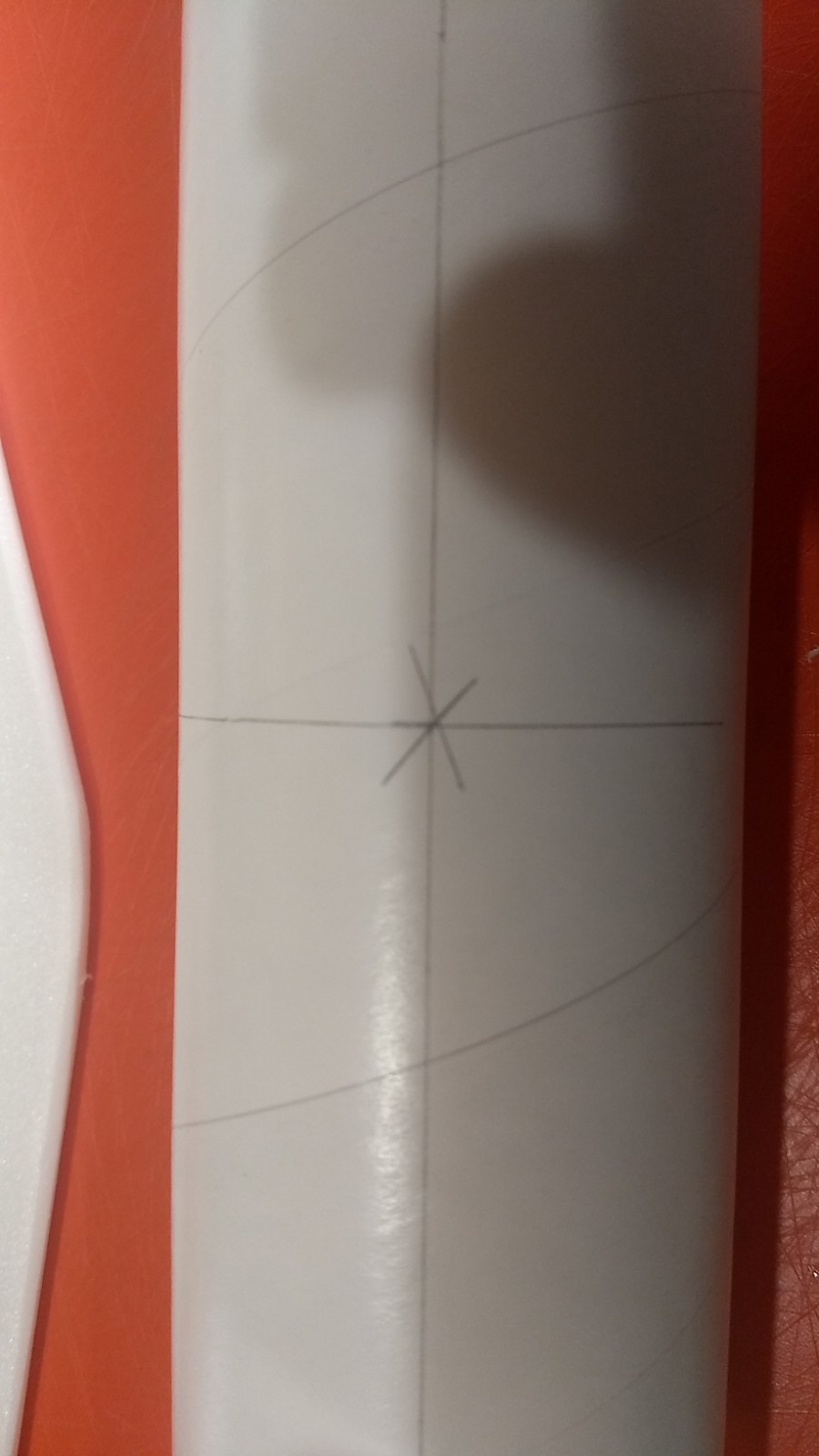
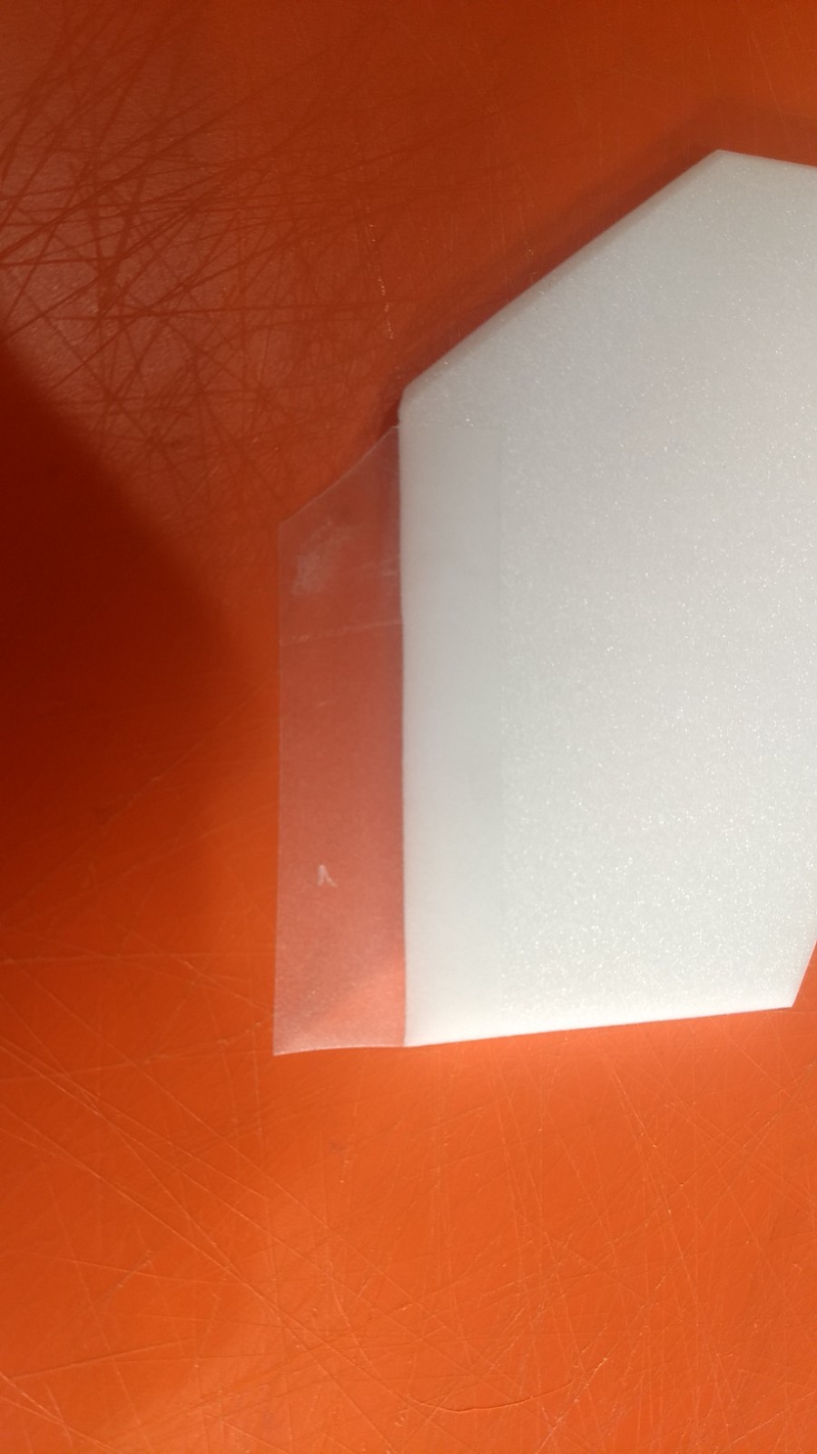
- Using the front of the nose cone and a spare piece of depron, push and rotate the front of the nose cone to make an impression of it in the foam. Use an exacto to cut out this disk.
- Insert the foam disk from the rear of the model, it will stop about 1/8″ from the front, this is what you want. Use something to support the foam disk so it stays flat and then apply a glue fillet on the front of the nose cone and disk and wait till it sets. I used the end of the lint roller as it had a good flat platform and fit into the rear of the cone.
- Once set apply a glue fillet inside the nose cone by dropping glue in from the rear. Once set glue the intake cone in the front of the nose cone keeping it centered. Apply a fillet and make sure it is set.
- If your kit came with a motor block ring, glue it to the front of the motor tube at this time.
- Glue the three foam centering strips onto the motor tube in three places, the alignment lines are there for reference but may not be perfect, make sure two are opposite each other and one is at 90 degrees to those two. The vertical stab tab will make the final centering piece when installing the motor mount.
- Install the two rail buttons in their respective holes if not already installed.
- Join the body tubes using the coupler, note the two tubes have arrow marks, make sure these are aligned as you glue them together.
- Unfold the wing and apply glue to the wing at the taped joint and set it on a flat surface to dry face down.
- The horizontal stabilizer has one elevon hinged, the other edge will be hinged after inserting into the body tube and before gluing in place.
- Insert the horizontal stabilizer into the slot in the body tube. Make sure the spar is facing down and the rail buttons are also facing down and the vertical stab slot is facing up
- You will now hinge the other control surface half. Apply a strip 2 5/8″ long of blenderm to the top of the control surface edge that has the 45 degree bevel. The bevel will be pointed down.
- Cut the tape at an angle to match the angled edge.
- Lay the model on the edge of a surface and have someone hold it for you so that the horizontal stabilizer is flat. Lay the elevon against the stabilizer and tape it to the stabilizer so that the edges are touching.
- Flip the elevon up and forward flat on top of the stabilizer then tape the beveled edge with another piece of blenderm tape. Make sure the elevon moves up and down freely.
- Make two holes with a toothpick in the bottom of the control surface you just hinged about 1/2″ outboard from the inside end the same as the holes on the pre-installed surface.
- Make sure the stabilizer is now centered in the body tube at the front and rear and the elevons have the same amount of clearance on both sides of the body tube. Glue the stabilizer in place.
- Test fit the wing into the slot in the body tube, then make sure the wing is centered front and back and glue in place when correct. You may need to trim a small amount of the coupler out of the pre-cut wing slot if you glued it in past the slot.
- Glue the vertical stab in place in the rear keeping it perpendicular to the wing and horizontal stabilizer. Apply a fillet inside the tube and on the outside.
- Test fit the motor mount into the rear of the model. You may need to sand the tabs on the mount so it will fit into the rear and under the vertical stabilizer tab. Make sure you insert so the motor block is forward. Keeping the vertical stabilizer still perpendicular to the wing, glue the motor mount in place against he body tube and vertical stabilzer tab.
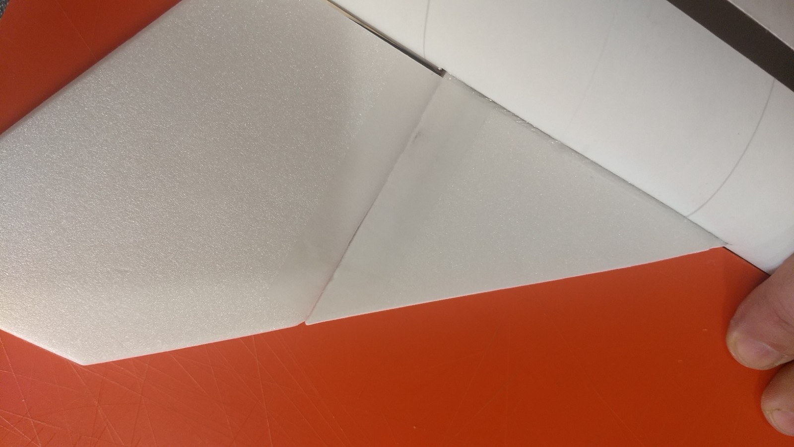
- Glue the two cockpit/conduit pieces together then sand the upper edges round, you may need to taper the rear slightly to match the width of the vertical stabilizer. Note there is a right and left hand cockpit/conduit and one edge is beveled, glue them together so that the bottom edge makes a V that way it will fit the top of the body tube without a gap. Glue the cockpit to the top of the body tube and against the vertical stabilizer.
- Glue each control horn in place on the bottom of the control surface using the pre made holes. The control horn holes should be pointing toward the front of the model. The pushrod should be closest to the center of the fuselage, there is a left and right control horn. Repeat on the other side.
- Put some CA on the top of the control surface where the horn prongs stick through, this locks it in place
The basic construction is now complete.
Radio Installation
Note: Your radio needs to be configured for Delta mixing, this means that the servo arms will move the same direction during elevator stick movement and opposite for aileron stick movement. Connect your servos to the receiver one in the aileron connection and one on the elevator connection and apply power. Use a servo arm at least 9/16” long and with holes small enough that there won’t be slop with the pushrod wire when installed. I use the hole furthest out on the servo arm, to maximize movement. On some servos there are a long two-ended servo arm, you can trim off one end if needed to get sufficient length. Zero out any trim settings on the transmitter.
- Connect a servo to each pushrod. If the pushrod is too tight, you can use twist an exacto knife in the servo arm hole to make it larger, but be careful and do not make it too large. Once connected, tape each servo in place near the bottom of the stabilizer temporarily so that the control surfaces are centered. Flip the model right side up and look at it from the rear. Moving the transmitter stick back(up elevator) should move both elevons up. Moving the transmitter stick to the right should move the right elevon up and the left elevon down. If you can’t get the servo reversing to give you the right polarity try swapping aileron/elevator inputs to the receiver or turning the servos over and swapping the servo arms to the other side of the output shaft. If that is correct, continue.
- Attach a servo extension that is 18-24″ long, long enough to reach to the front of the model and attach to the battery.
- Flip the model upside down and supported. Mark where each servo would go to have the control surface centered, then cut a slot into the body tube to fit the servo and insert the servo so that the pushrod makes a straight path to the elevon. You’ll need to route the servo wire through the hole and re-attach it to the receiver at the front.
- With the radio still on, put a small amount of glue on the bottom of the the servo, being careful not to get any near the output shaft then re-insert it into the pocket in the body tube and gluing it to the bottom of the horizontal stabilizer. Keep the surface level as you do this. Do the same to the other side. Make sure the glue is set before continuing. See pictures for help.
- Flip the model back right side up. Make sure the control surfaces are centered, use trims if needed. Now measure the control surface movement. Full elevator movement should be 1” in each direction, aileron movement should be 1″ in either direction. Since the model will be nose heavy, extra elevon movement helps to give sufficient authority during glide.
- If you have a flap/elevator mix you can program up elevator to a switch setting. The model needs approximately 1/2″” of up elevon during glide. If you can’t set the up elevator trim to a switch on your radio you’ll have to manually put in boost and glide trim which is hard to do while flying the model.
- Attach the receiver inside the nose cone with the provided velcro.
- Attach the flight battery into the nose cone with the rest of the provided velcro.
- Finish the model as desired, see general instructions for paint recommendations and warnings. I did not paint mine to keep it light. I used a sharpie pen and clear drawing triangles to make panel lines using the guide and it adds a lot to the model and doesn’t take that long. If you purchase the sticker shock decals refer to the pictures for placement. After application of the vinyl use a hot hair dryer to soften decals and press them in with your thumb to make them set and conform to the model.
- Balance the model after you have painted it.
- Insert your heaviest loaded rocket motor into the motor mount and install the flight battery as if you were going to fly it.
- Support the model right side up at the balance point indicated for boost. Glue pieces of the included lead weight in the nose or tail as needed to balance it. Do not try to fly the model with it balancing it behind this point or significantly nose heavy. The adage is, a nose heavy model flies poorly, a tail heavy model flies once.
Flying: See the General Information link at the top for flying instructions. Be ready on the first few flights to keep the model straight till you have the trims set perfectly for boost and glide.
-
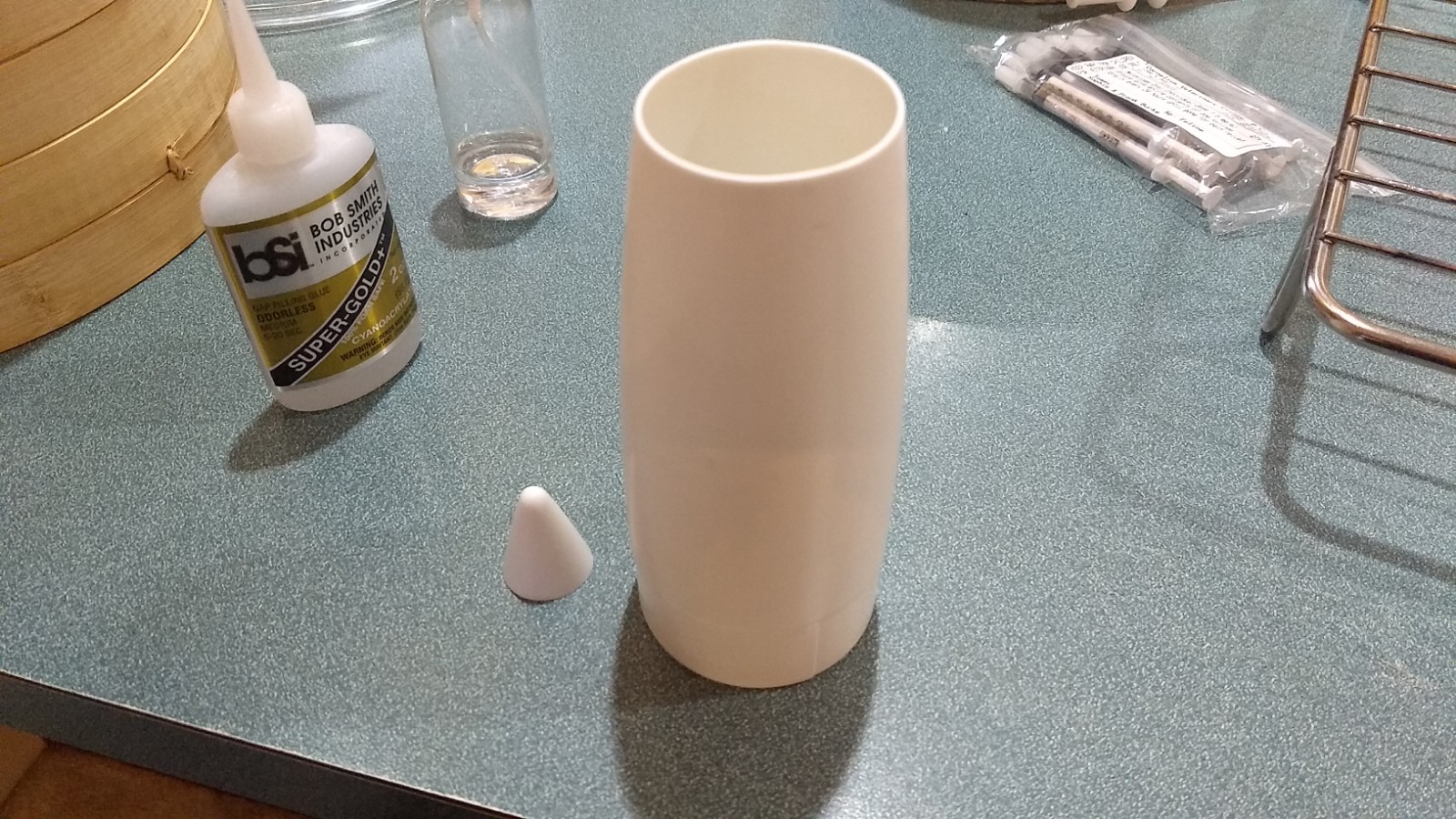
- Nose cone pieces
-
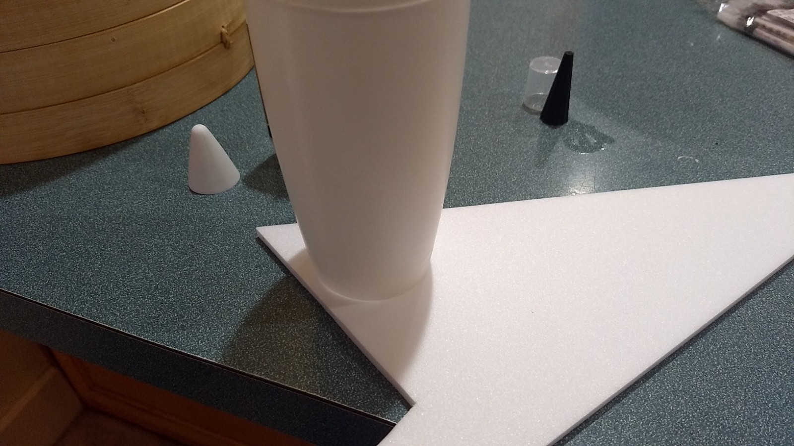
- Press cone into spare foam
-
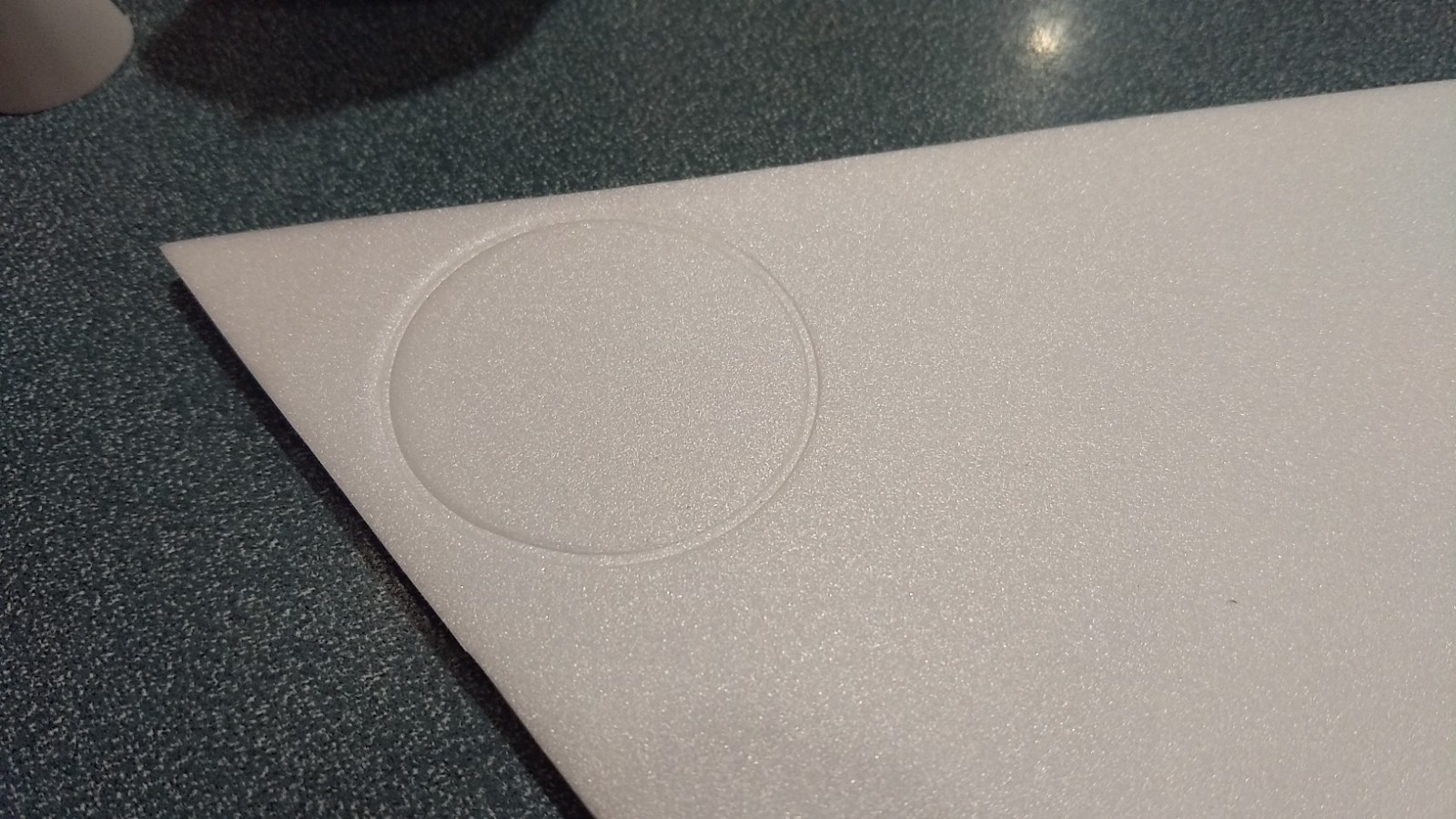
- Cut out disk
-
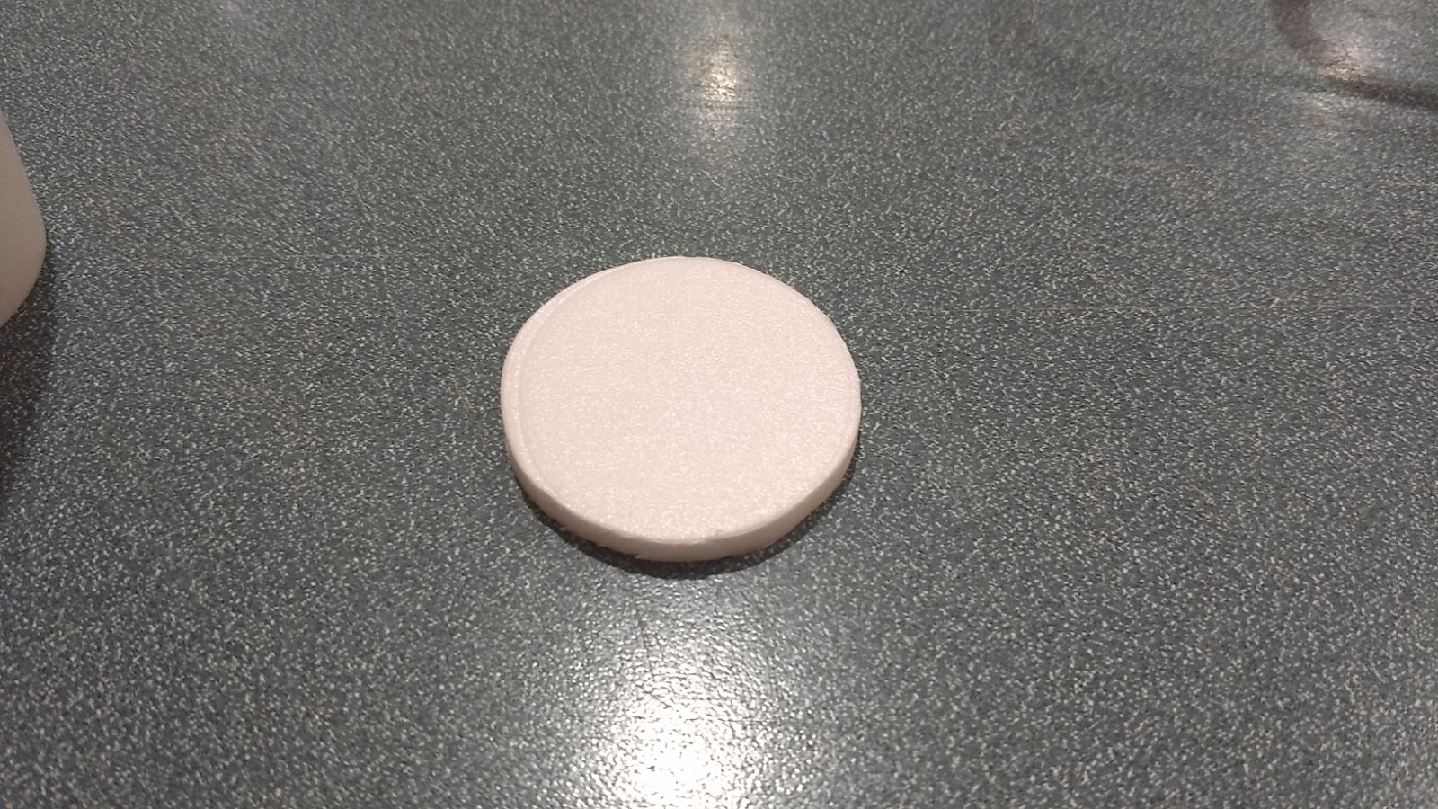
- Foam disk cut out
-
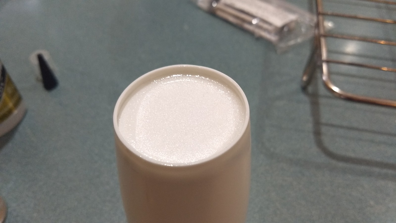
- Glue disk into cone from inside
-
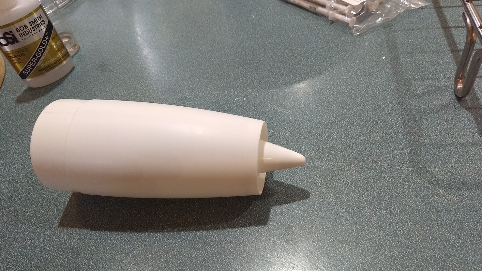
- Glue nose cone tip into center of foam disk.
-
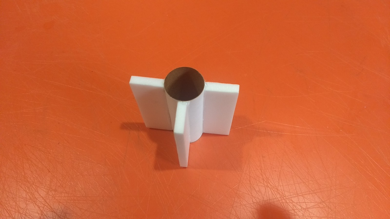
- Motor mount assembled.
-
- Join the two body tubes keeping the arrows aligned
-
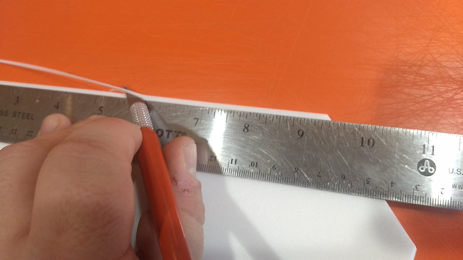
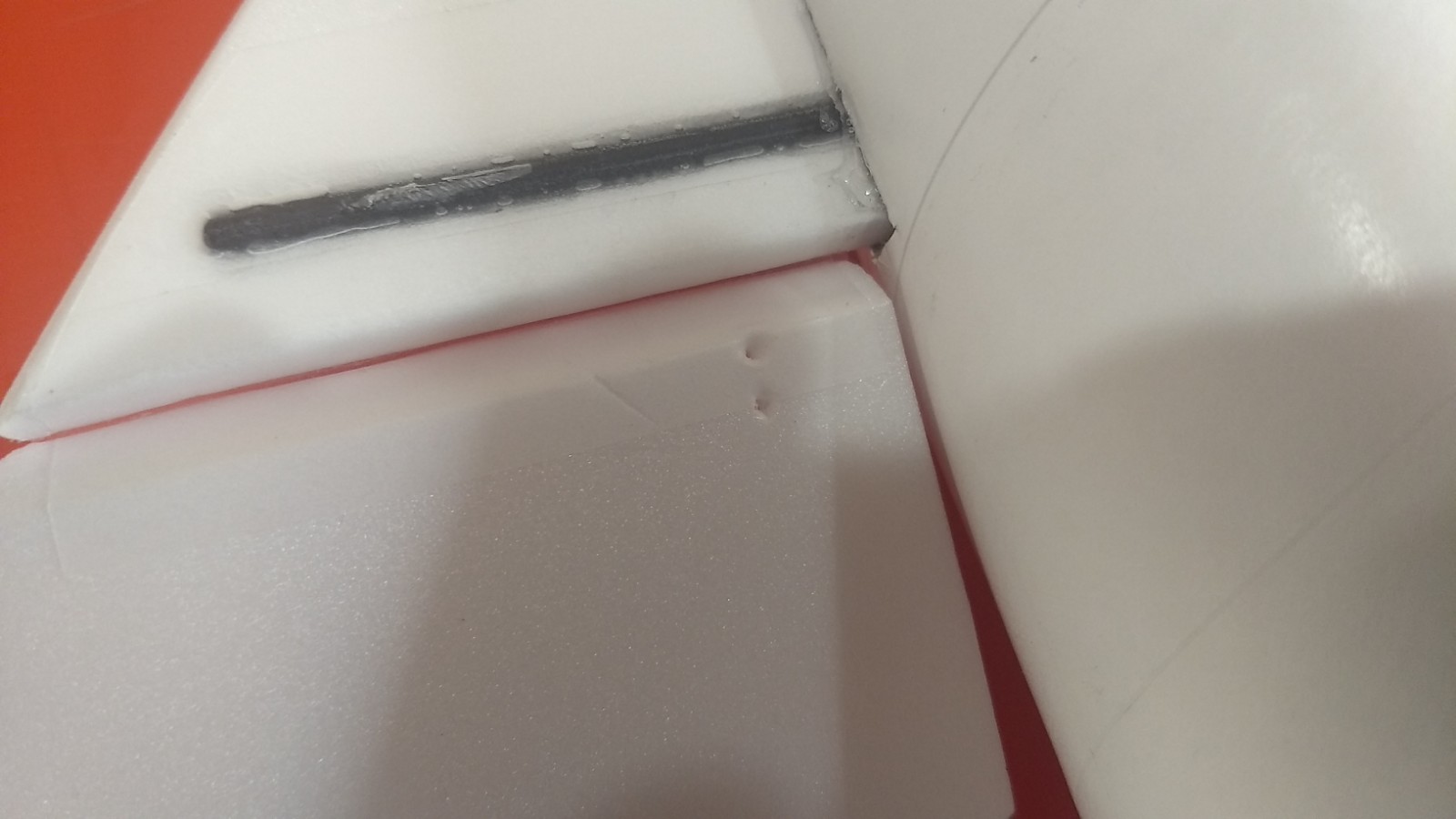
- Beveling the edges of the wing and tail surfaces.
-
- Apply tape to elevon on top
-
- Insert the stabilizer into the body tube then tape loose elevon to top rear of stabilizer.
-

- Fold elevon forward and tape the beveled edge to complete the hinge.
-
- Make two holes in the elevon for the control horn on bottom of surface.
-

- Horizontal stabilizer assembly installed.
-
- Glue the taped wing joint then insert the wing into the body tube slot, make sure it is centered and glue in place, make sure the spar is pointed down.
-
- Vertical stab glued in place.
-
- Test fit motor mount
-
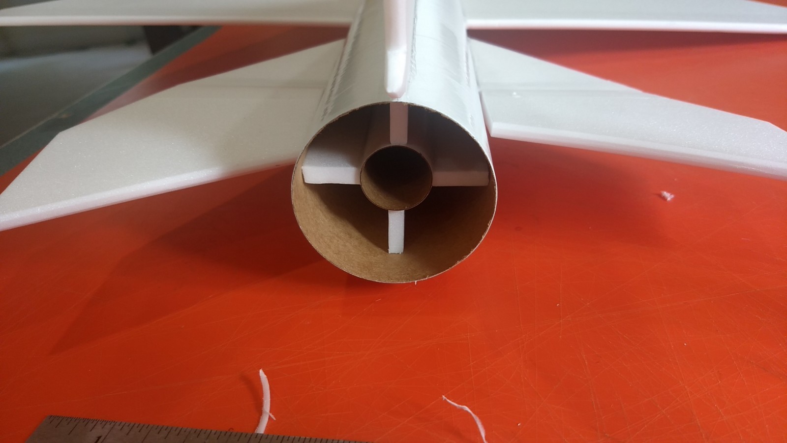
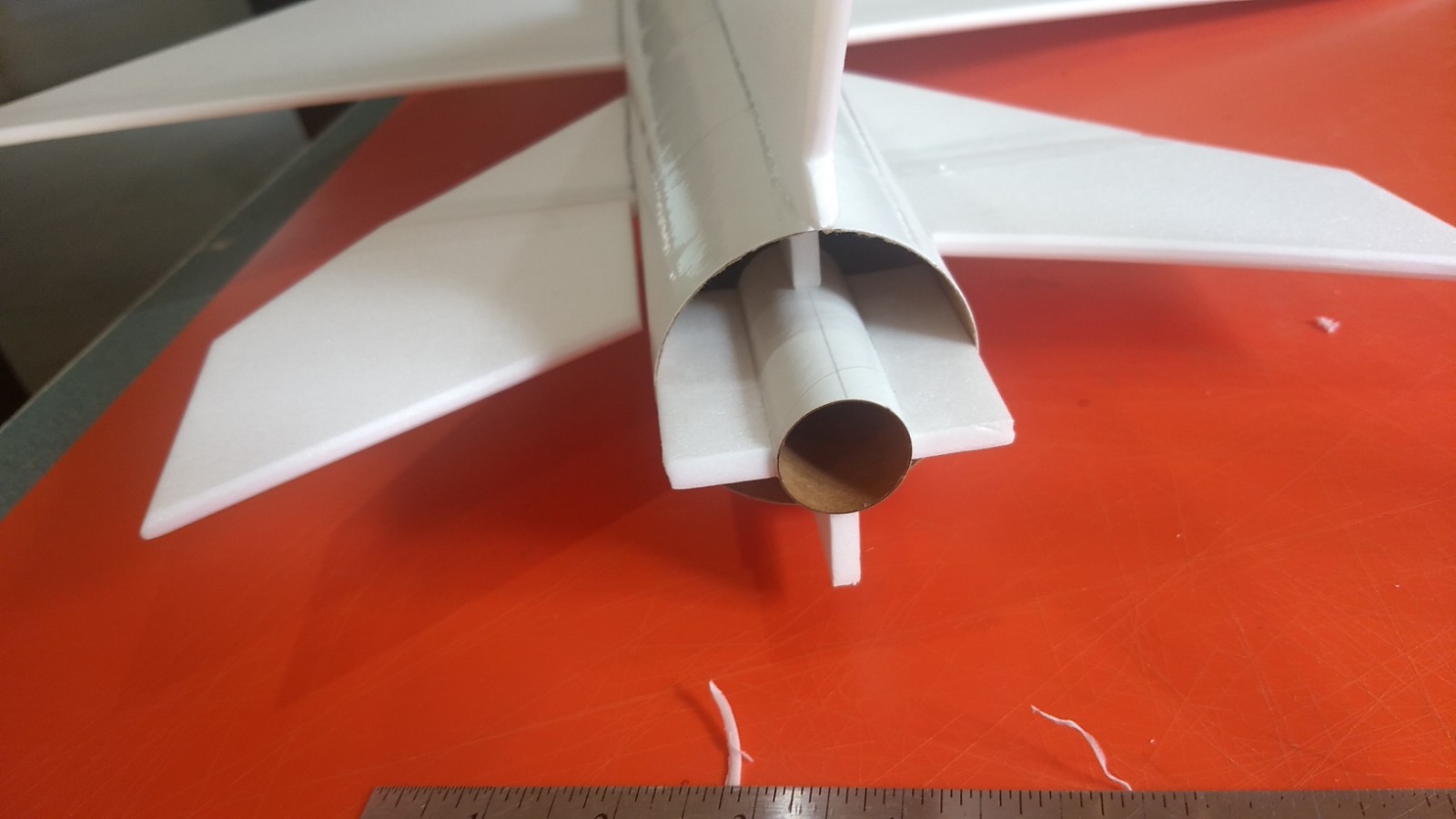
- Motor mount installed.
-
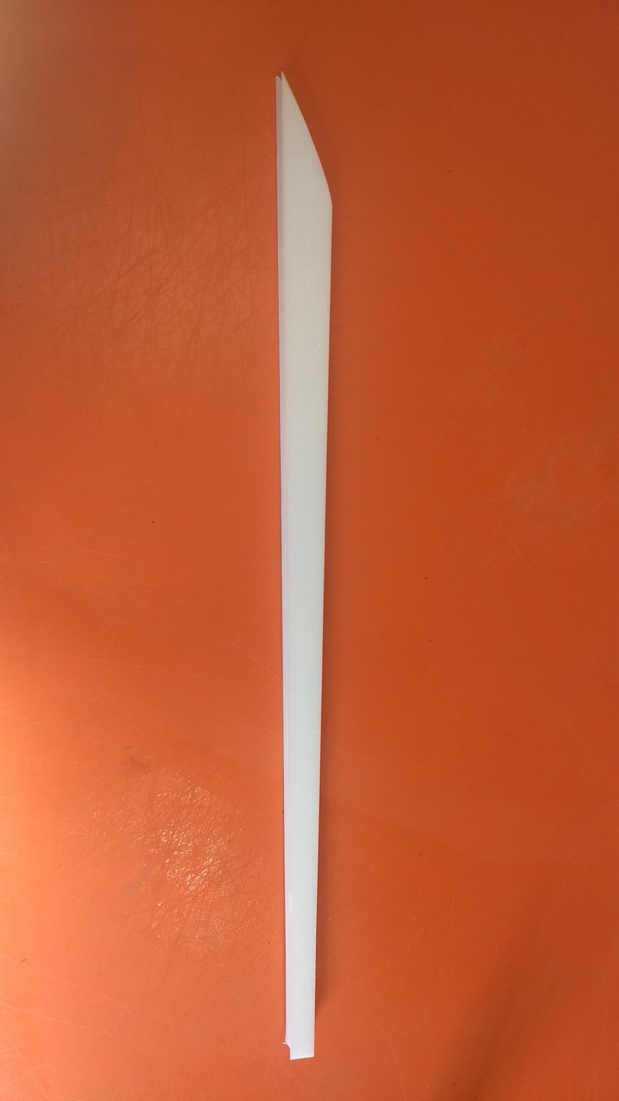
- Cockpit/conduit glued together
-
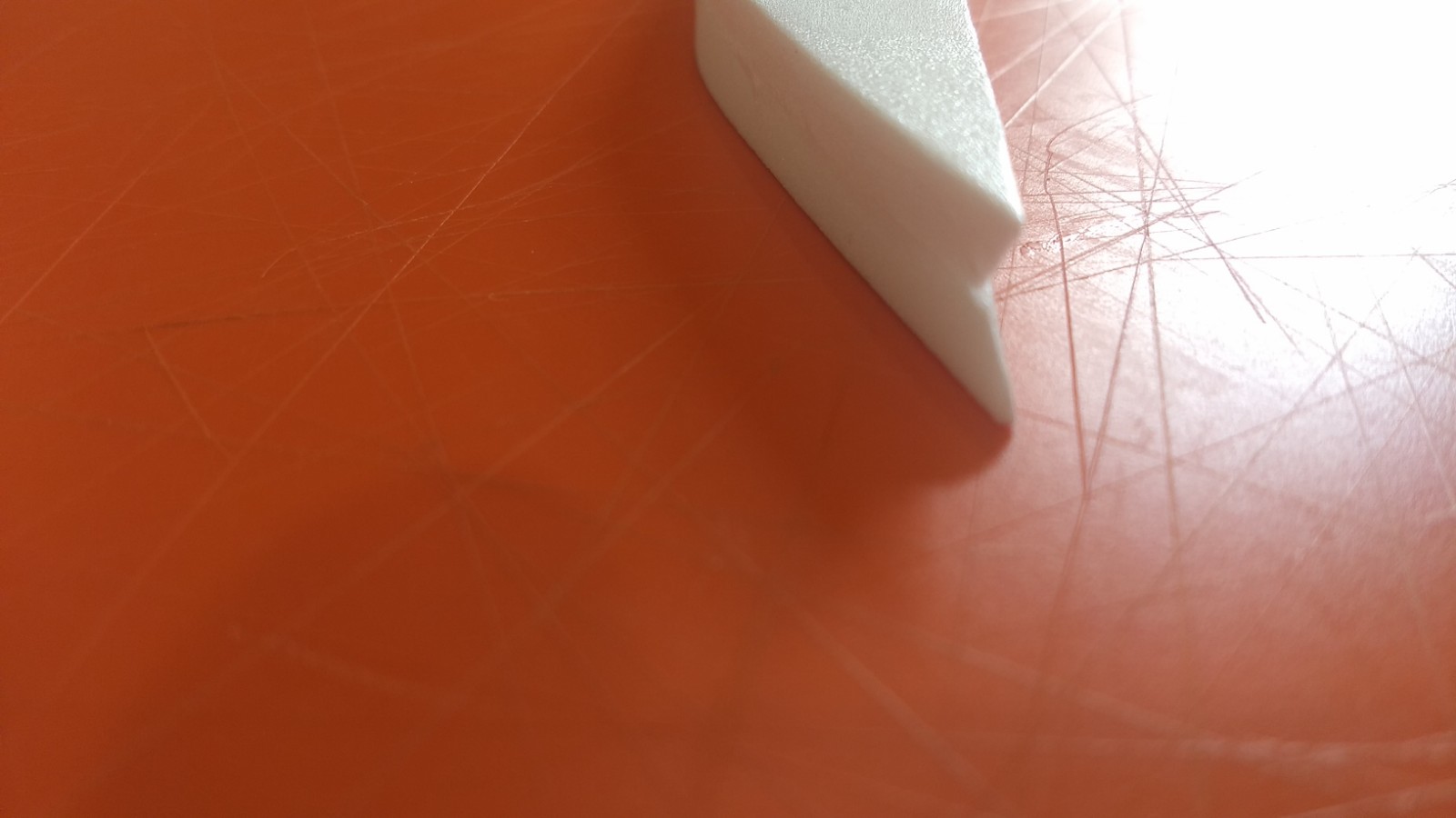
- Conduit showing V notch in bottom to fit the body tube contour.
-
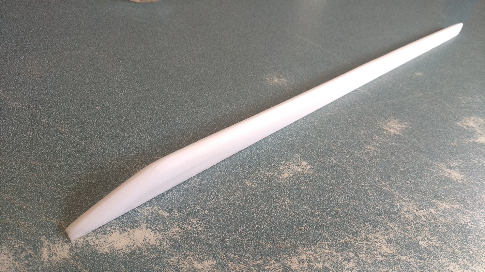
- Cockpit/conduit shaped.
-
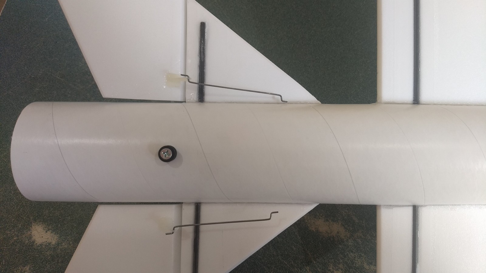
- Pushrods and control horns installed.
-
- add glue to the top of the control horn prongs.
-
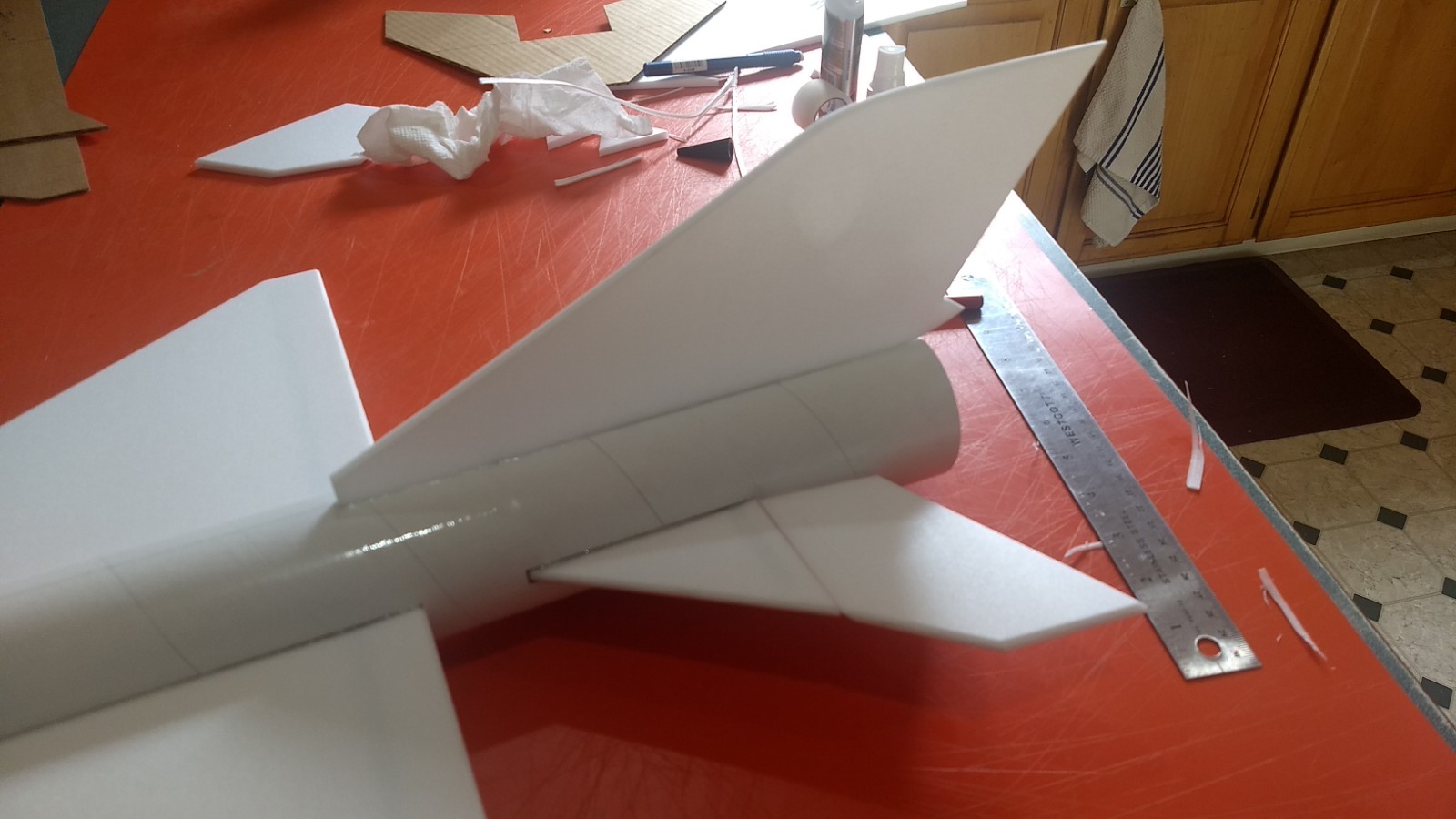
- Completed Airframe
-
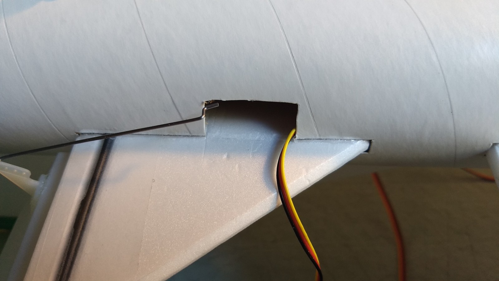
- Pocket cut for servo
-
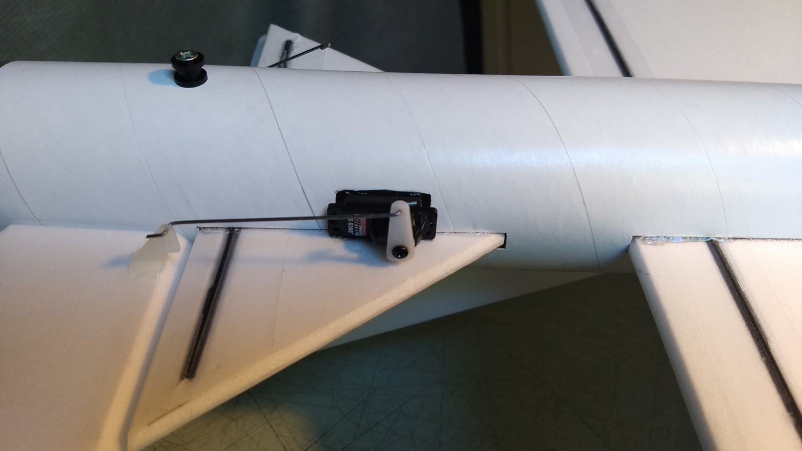
- servo wire routed to the front and servo installed and glued in place with control surface level.
-
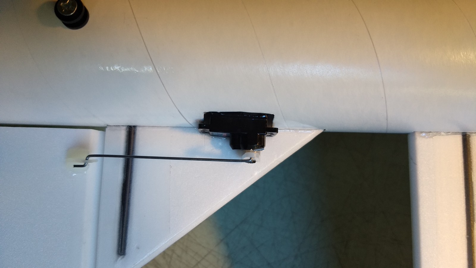
- Top view of servo
-
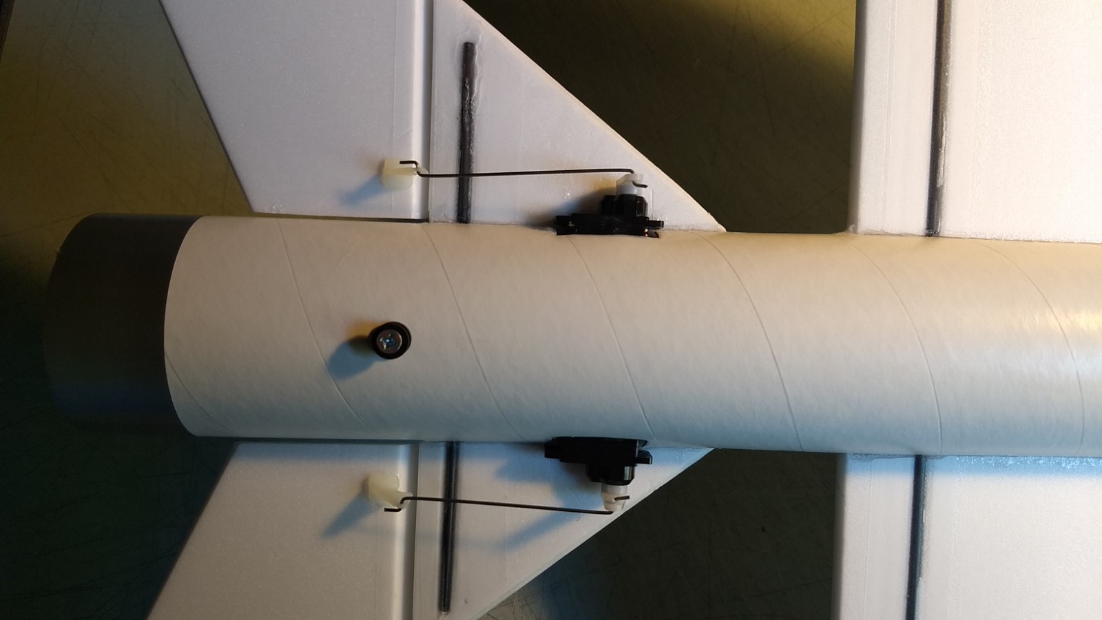
- View of both servos installed.
-
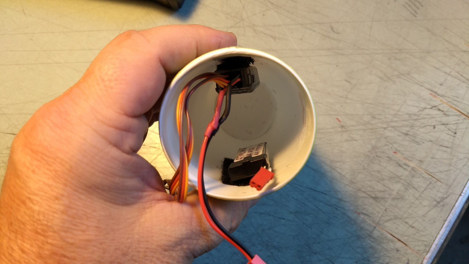
- Receiver and battery installed in nose cone.
-
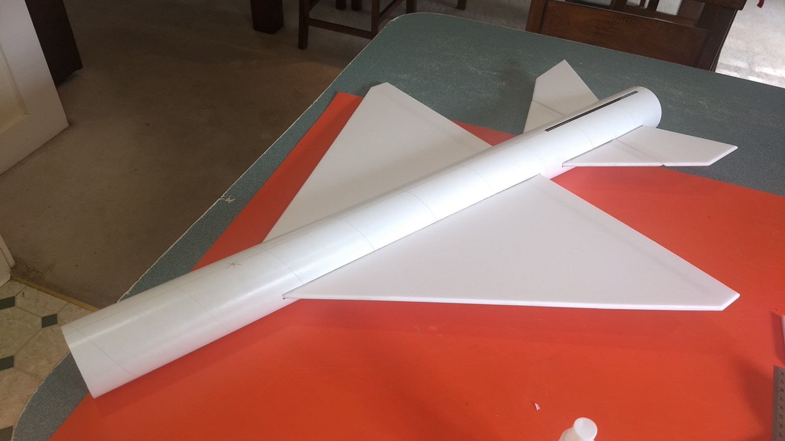
- Completed model
-
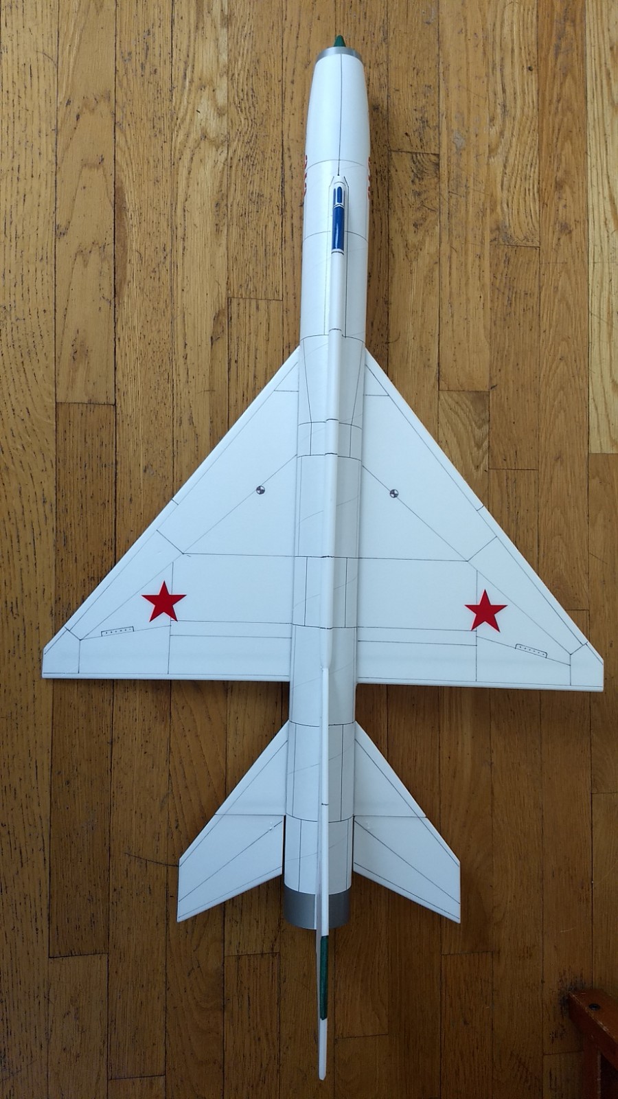
- Top view
-

- Rear view
-

- Panel line guide