The X-15 Delta Configuration RC Rocket glider kit is modeled after the proposed X-15 modification to allow sustained flight above Mach 6.7. It features a clipped delta wing, diamond shaped wingtips. It has a light wing loading giving it a very nice glide and easy/stable boost. It comes with a plastic nose cone, 2.6″ white tubing for the body and 9mm depron wing and tail surfaces. Construction is very simple and takes about an hour and a half. Elevons are pre-hinged, the rail buttons are pre-installed and the body tube is pre-slotted for the wing. The wing spar is pre-grooved for the spar. You will need two 10 gram type servos, two 16″-18″ servo extensions, a receiver, and a small 500mah single cell lipo battery. You will need a transmitter with delta or elevon mixing. Length 37″, wingspan 20″, weight rtf 11.75-12.25 oz.
CG location for rocket flight: 13.2″ forward of the rear end of the body tube.
High quality cut vinyl decals are available for this model for a white scheme(black letters) or white letters, Decals Available HERE
*Note the decals fit three different kits but are identical except for the cockpit decals. The set comes with cockpits for all three kits, and has both round and rectangular decals for this kit.
Identify all pieces, the kit should contain:
1 wing taped together
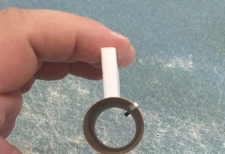
2 rail buttons/t-nuts
1 Vertical Stabilizer
1 Motor mount
1 Nose Cone
1 wing spar(carbon fiber)
1 coupler
2 Body Tubes
2 wingtips
1 ventral fin
3 canopy pieces
2 control horns/Pushrods
1 motor mount centering strips, 6mm by 2.75″
Velcro(for battery and rx/bec attachment)
3M blenderm tape
Lead weight
Spare depron
Notes before starting:
Reference to CA+ means foam safe CA+, normal CA+ will melt the foam! Normally you need to use accelerator to get the CA to set on the foam since there is nothing for it to soak into and activate.
Epoxy is not needed in this model. Weight is critical and the model is designed for the thrust and flight loads. Weight in the rear end is bad and will require additional weight in the front of the model.
Unpacking your kit:
The kits are packed to protect them in shipping, but the contents are fragile so unpack carefully. Carefully cut the tape holding the tubes in the box, then unwrap/lightly cut the plastic wrap to free the tubes, the spar may be packed in the tubes and the baggie with the little parts and nose cone will be in the tubes as well. Carefully cut the tape holding the cardboard wing protector in the box and carefully remove it, don’t pull hard or bend it. Then carefully cut the tape holding the cardboard top piece to the bottom. There may be some sticky tape holding the cardboard to the bottom cardboard piece, carefully peel it being sure not to bend anything. Once the top cardboard is free you can see the foam wing/tail parts, there are little fragile pieces in here, so unwrap carefully. It may be best to use an exacto to lightly cut the plastic wrap and carefully remove it without cutting into the foam. Make sure everything is free before you remove the pieces to avoid breaking anything. Kits contain one or two scrap pieces for repairs if you damage anything in construction or flight, just cut and patch in a spare piece of the foam if needed using foam safe CA+.
Assembly:
- There is a wrap on the main body tube to help hold it’s shape, once the slot is cut it wants to flatten, leave that in place till you are ready to insert the wing, then remove it.
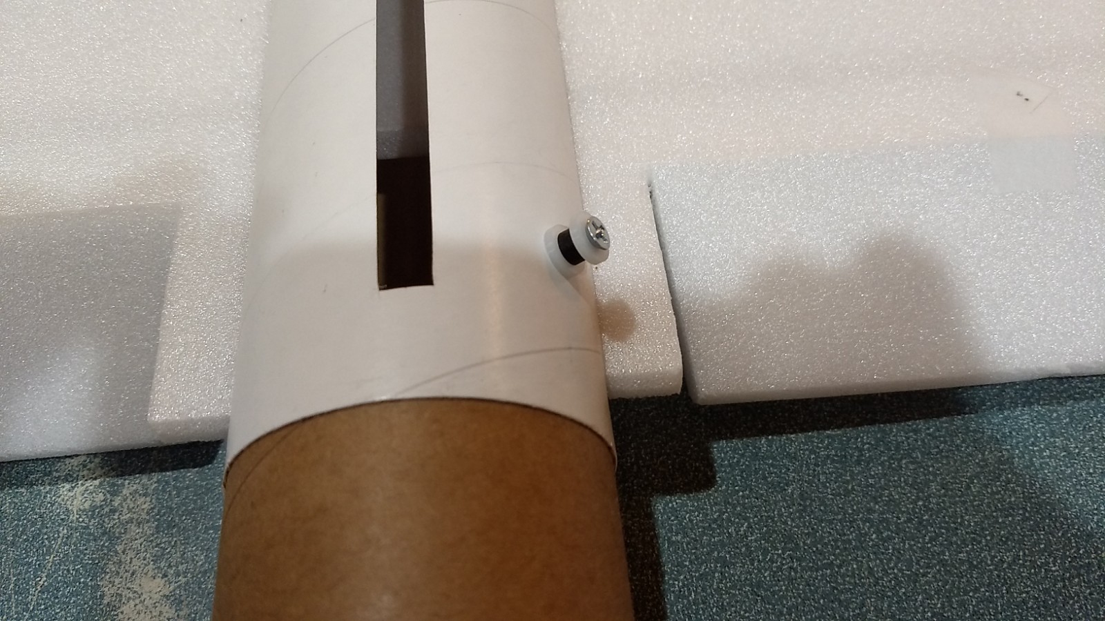
- Install the two rail buttons and t nuts in the pre-cut holes. The t nut goes on the inside, then put a washer, then collar, then washer then screw.
- Glue the centering strip on the motor mount on any one of the lines
- Unfold the wing and glue the joint using CA+ and accelerator, make sure it is flat.
- Glue the wing spar in the pre-slotted area on the bottom of the wing with CA+ and then tape over the spar and wing joint with the included blenderm tape.
- Insert the coupler into the rear of the body tube just 1/2″ or up to the slot for the wing, this is so the rear of the tube is round which is helpful for centering the wing.
- Test fit the wing in the slot in the rear body tube, if it is snug, sand or trim as you don’t want it to drag/damage the wing as you are inserting it. Note, the rail buttons are on the top side of the fuselage and visible wing spar is facing down, the vertical stab slot will be up. Make sure the wing is centered left and right at the front and rear, then tack glue the top and bottom at the front and rear of the wing, making sure not to glue the coupler in place!! Remove the coupler when the glue has set.
- Now glue the wing in place on both sides top and bottom, do a little at a time, once the slot is cut in the tube, the tube tends to flatten, you may need to squeeze the tube slightly as you go to keep it round.
- Test fit then glue the vertical stab into the slot in the rear body tube. Make sure it is perpendicular to the wing.
- Insert the motor mount from the rear and into the slot in the wing. The taped portion of the motor hook will be forward and the tab will vertical at the bottom. The wing and vertical stab tab will help center the tube. It should be recessed about 1/2″ into the body tube when fully inserted. You may need to sand the motor mount tab till it will slide in freely.
- Run glue on the motor mount tabs to glue them to the body tube the the other places the foam contacts the motor mount. You don’t need a lot of glue here as the motor pushes against the rear of the wing which is glued in its’ slot so it can’t really go anywhere.
- Glue the coupler the front of the body tube tube until it stops against the rail button t nut.
- Glue the forward short body tube onto the coupler, there is a small alignment mark on the bottom to make sure the pieces are aligned, these tubes are cut by hand so aligning the mark makes sure the joint has no gaps.
- Test fit then glue the two wing tips to the wing using the tabs/slots. The shorter portion points down to have clearance on landing. Note there is a left and right, make sure they are perpendicular to the wing, and the pre-cut angle cuts on the edges are on the outside.
- Glue the ventral fin on the bottom. Once attached, you may want to apply some CA+ to the edges to help harden it against landing damage.
- Glue the control horns in place on the bottom of the control surfaces, the holes face forward and the pushrod should be closest to the body tube.
- Canopy: The canopy takes a bit of time so just go slow and careful. Once you think you are done take a look at it and make any changes you think you need to to make it look the way you want before gluing it in place. I used a combination of exacto knife, 320, and 400 grit paper.
- Glue three of the canopy pieces together(three are spares if you mess up)
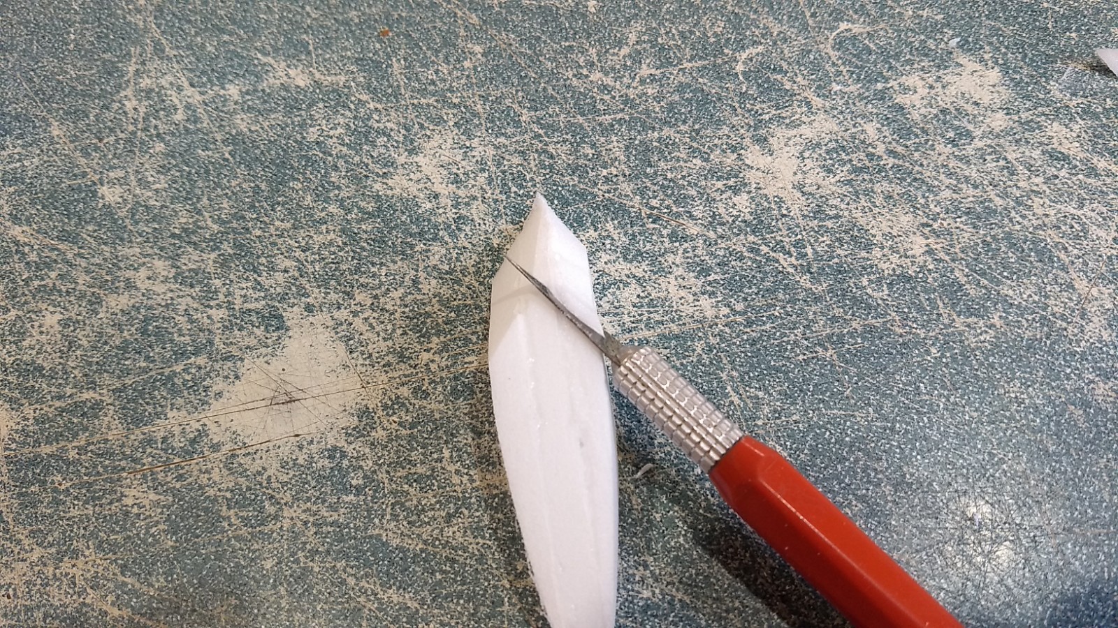
- Taper the rear of the canopy stack as shown in the photo, looking down from the top.
- Cut the front two corners of the canopy at an angle so they meet in the middle. You will sand these more as needed as you progress.
- Round the rear top corners to a nice shape leaving the top part a little flat.
- Using sandpaper over the nose cone sand the bottom so it makes a nice contour to match the cone so there are no gaps when you glue it in place.
- Glue it in place so the rear is 3/4″ from the rear of the cone where the shoulder starts.
- Once glued, use a very light coating of CA+ foam safe to coat the canopy and harden it. Use VERY light coats a little at a time and let air dry, otherwise it can eat into the edges of the cone. If you have any gouges, you can use a white lightweight filler.
The basic construction is now complete.
Radio Installation
Note: Your radio needs to be configured for Delta mixing, this means that the servo arms will move the same direction during elevator stick movement and opposite for aileron stick movement. Connect your servos to the receiver one in the aileron connection and one on the elevator connection and apply power. Use a servo arm at least 9/16” long and with holes small enough that there won’t be slop with the pushrod wire when installed. I use the hole furthest out on the servo arm, to maximize movement. On some servos there are a long two-ended servo arm, you can trim off one end if needed to get sufficient length. Zero out any trim settings on the transmitter. The model once the motor has burned out is nose heavy and flying wings lose pitch authority when nose heavy so you want as much up elevator travel for trim/flare as possible.
- Connect a servo to each pushrod. If the pushrod is too tight, you can use twist an exacto knife in the servo arm hole to make it larger, but be careful and do not make it too large. Once connected, tape each servo in place so that the control surfaces are centered. Flip the model right side up and look at it from the rear. Moving the transmitter stick back(up elevator) should move both elevons up. Moving the transmitter stick to the right should move the right elevon up and the left elevon down. If you can’t get the servo reversing to give you the right polarity try swapping aileron/elevator inputs to the receiver or turning the servos over and swapping the servo arms to the other side of the output shaft. If that is correct, continue.
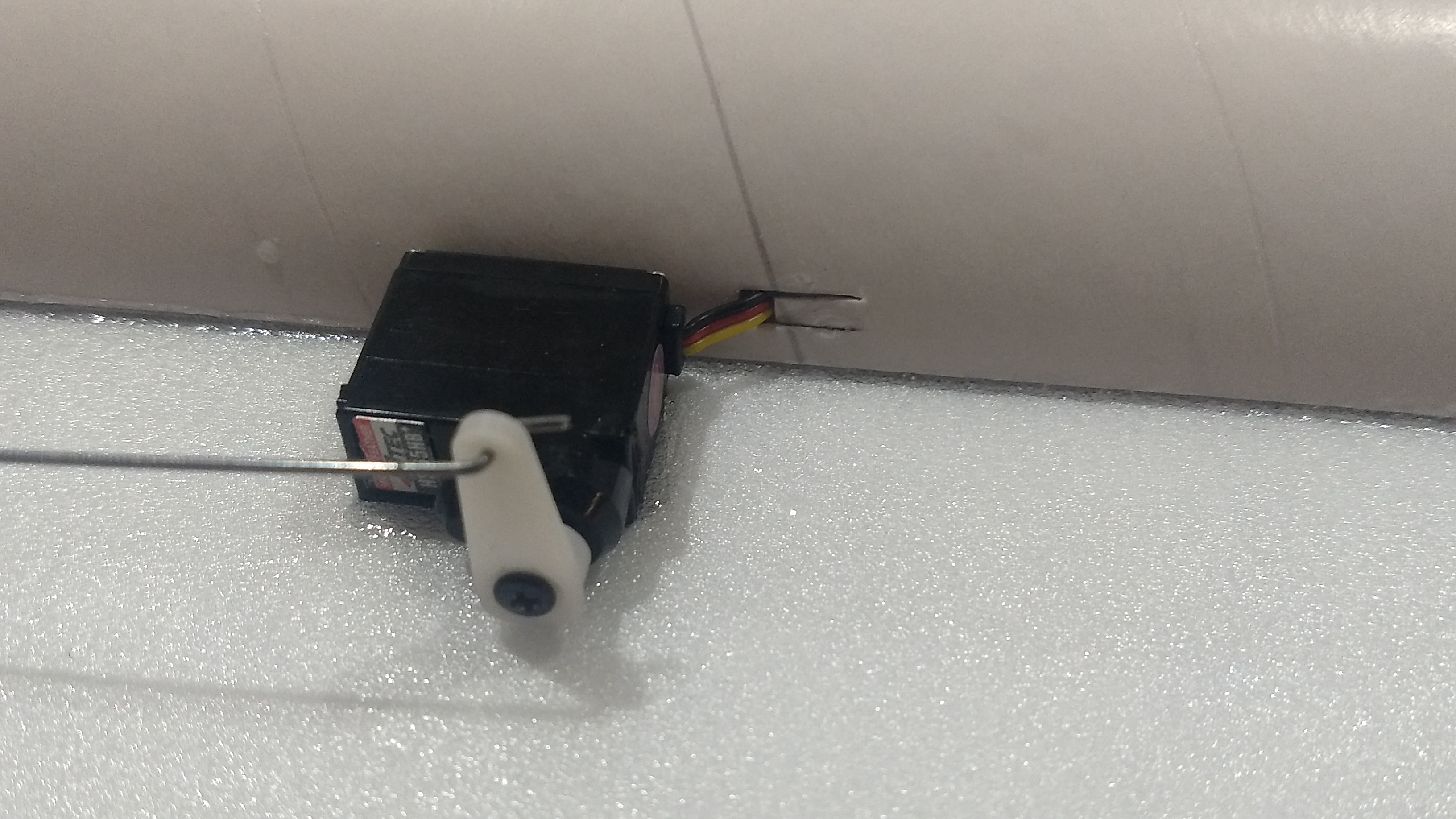
- Flip the model upside down and supported. The servos may be attached to the model using double back servo mounting tape(not included) or by directly gluing the servo to the wing with CA+ or a small amount of epoxy. Double back servo tape can loosen over time and with exposure to heat, I prefer to glue the servo in place. With the radio still on, put a small amount of glue on the servo, being careful not to get any near the output shaft. And set it in place on the model keeping the control surface centered. Do the same to the other side. Make sure the glue is set before continuing. The servo and pushrod should be at 90 degrees to the hinge line so that it moves easily and fully.
- Flip the model back right side up. Make sure the control surfaces are centered, use trims if needed. Now measure the control surface movement. Full elevator movement should be 1” in each direction, aileron movement should be 1/2″ in either direction. Since the model will be nose heavy, extra elevon movement helps to give sufficient authority during glide.
- If you have a flap/elevator mix you can program up elevator to a switch setting. The model needs approximately 3/16″ to1/4” of up elevon during glide. If you can’t set the up elevator trim to a switch on your radio you’ll have to manually put in boost and glide trim which is hard to do while flying the model.
- Attach a 16-18″ servo extension to each servo.You just need to be able to route the wire to the front of the tube to attach it to the receiver.
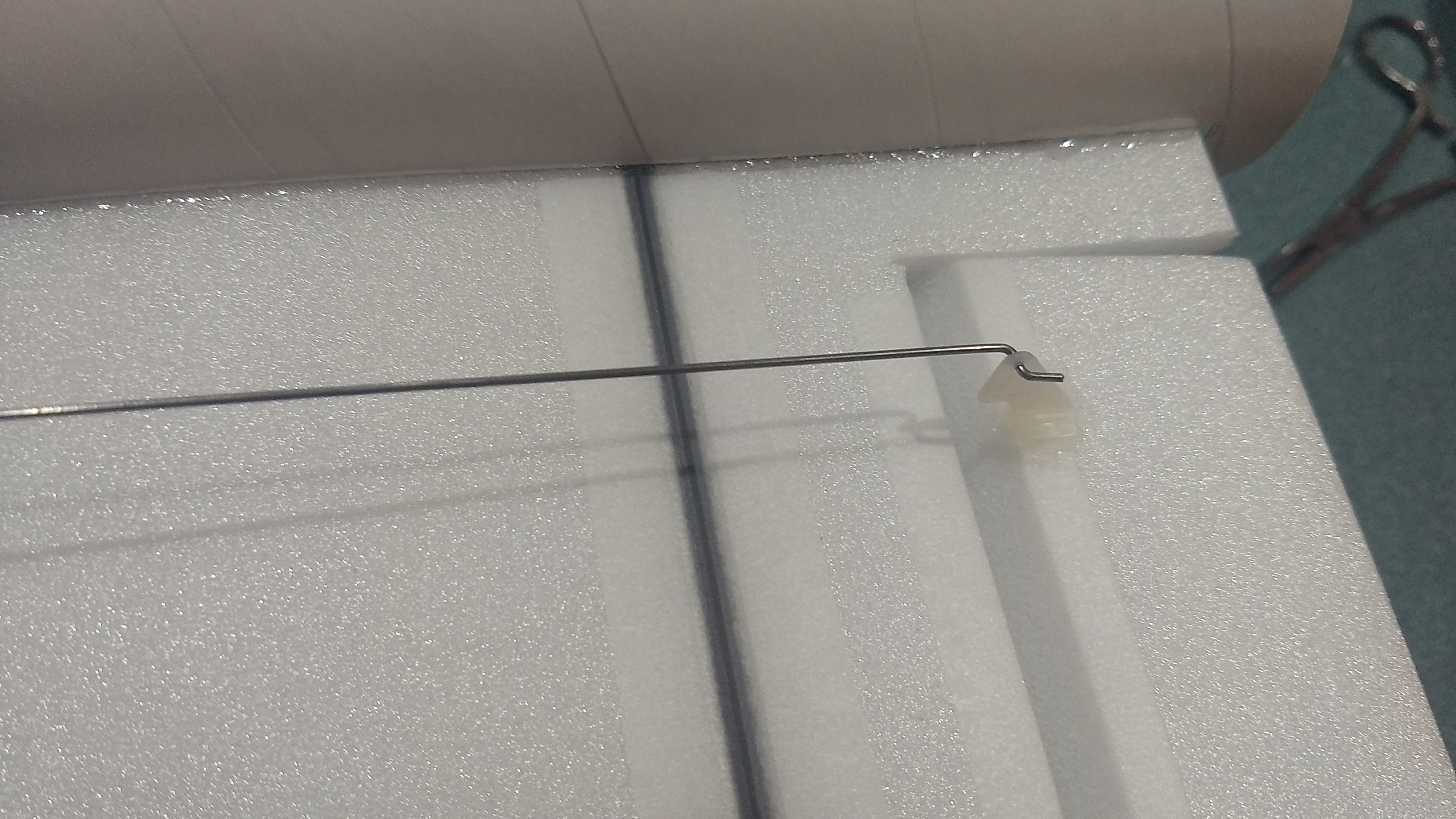
- Make a 1/8″ wide by 1/2″ long slot in the bottom of the wing/fuselage on each side and pass the wires through to the inside and toward the front. On my model I just made a U shaped cut, folded the cardboard forward, inserted the wire then folded the cardboard back over the slot/wire. I then taped over that with blenderm tape to avoid having a large open slot. See photo for more clarity. You can also just cut the slot out completely and cover it over with tape after inserting the wire.
- Attach the servo wires to the receiver and make sure they are going the right direction. Tape over the slots in the body tube.
- Use the included Velcro to attach the receiver inside the front of the body tube recessed enough to clear the nose cone shoulder. It may be desirable to wait to place the velcro to see how the balance is, I was able to avoid nose weight by simply moving the RX into the nose cone slightly because my servo extensions were long enough.
- Use the included velcro to attach the battery inside the shoulder of the nose cone, it may be desirable to wait to place the velcro to see how the balance is, I was able to avoid nose weight by simply moving the battery slightly by an inch or two.
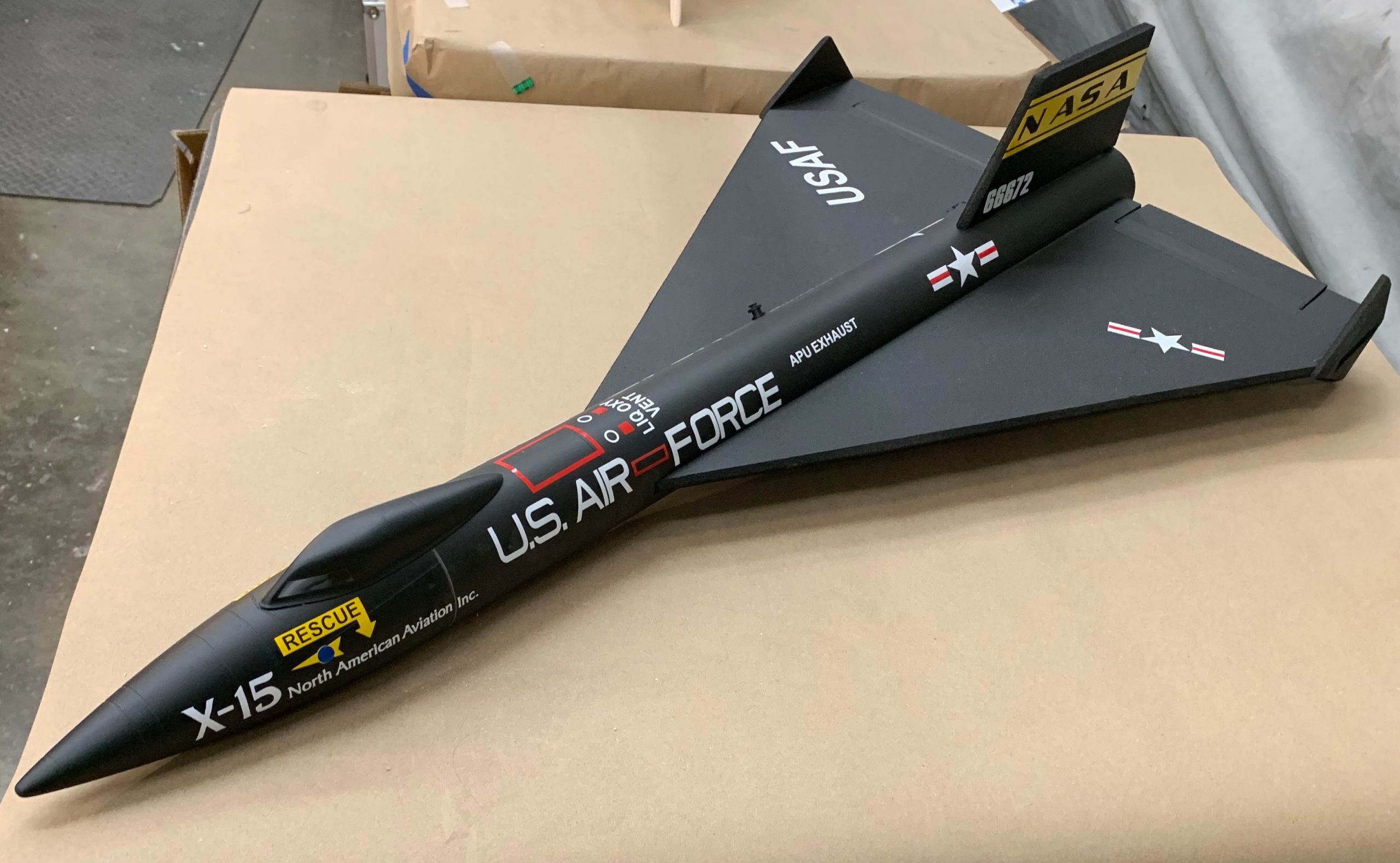
- This model can be done in White or Black scheme, decals are available for both on the link above. Most of the drawings show the model in Black, but for hypersonic flight it would have surely needed white ablative applied, your choice.
- For painting, I only use Testors enamel small rattle can and cannot recommend any others as it may cause melting/surface deformation. Do not spray too close or too thick as the solvents can damage the foam, spray in light coats. Paint will add 1/2-3/4 ounce to the flight weight. Make sure to mask off the servos. Make sure no paint will get on the servo output arm. Flat black is best for this model. If you have an airbrush, water based acrylics may work, but I have not used these, test on a piece of scrap foam in any case before applying to the model.
- With the vinyl from stickershock23 it helps once applied to use a hair dryer on hot to soften the material and then push it down onto the model with a towel. It helps it confirm and stick much better, especially on painted surfaces.
- On my white model prototype I added a few more red line accents with red fine line tape, feel free to embellish if desired.
- Insert your heaviest loaded rocket motor into the motor mount
- Support the model at the balance point indicated for boost. I use two pencils with the eraser pointed up and held in place with a small hand vice. Place the model upside down on the pencil erasers on the balance point indicated in the kit spec sheet. Use the included lead weight to balance it. Do not try to fly the model with it balancing it behind this point. The adage is, a nose heavy model flies poorly, a tail heavy model flies once. Make sure you do this after you painted your model as this will add tail weight.
Flying: See the General Instruction/Information link at the top for flying instructions. Be ready on the first few flights to keep the model straight till you have the trims set perfectly for boost and glide.
-
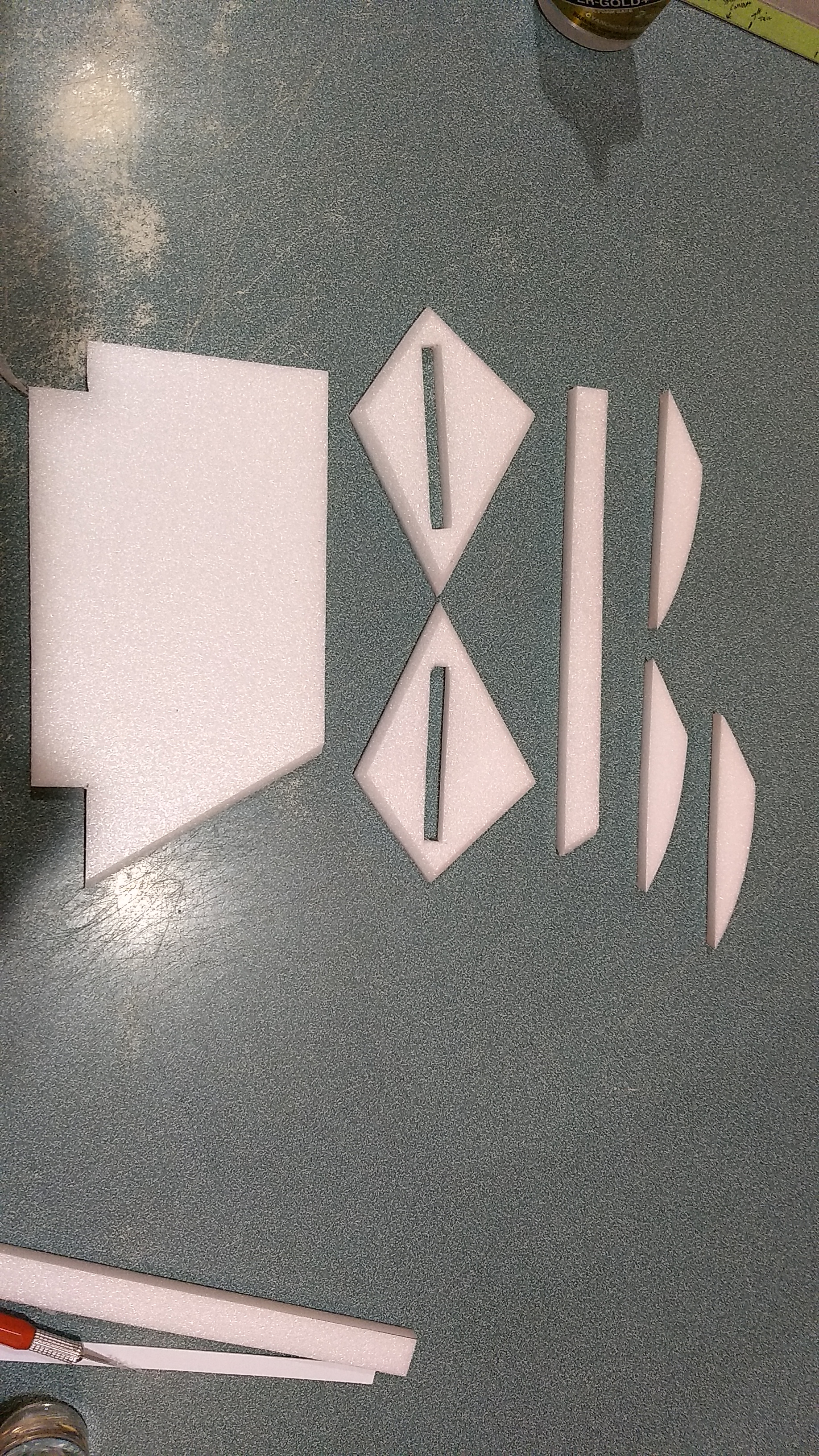
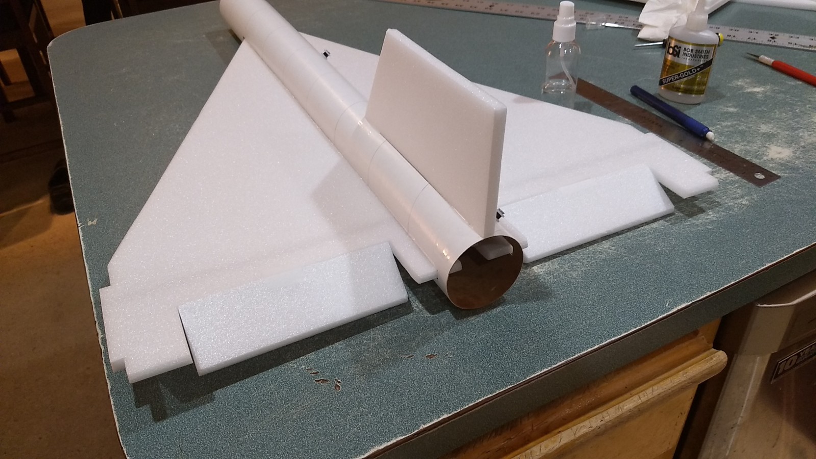
- Stabilizer and canopy pieces
-
- Motor tab installed
-
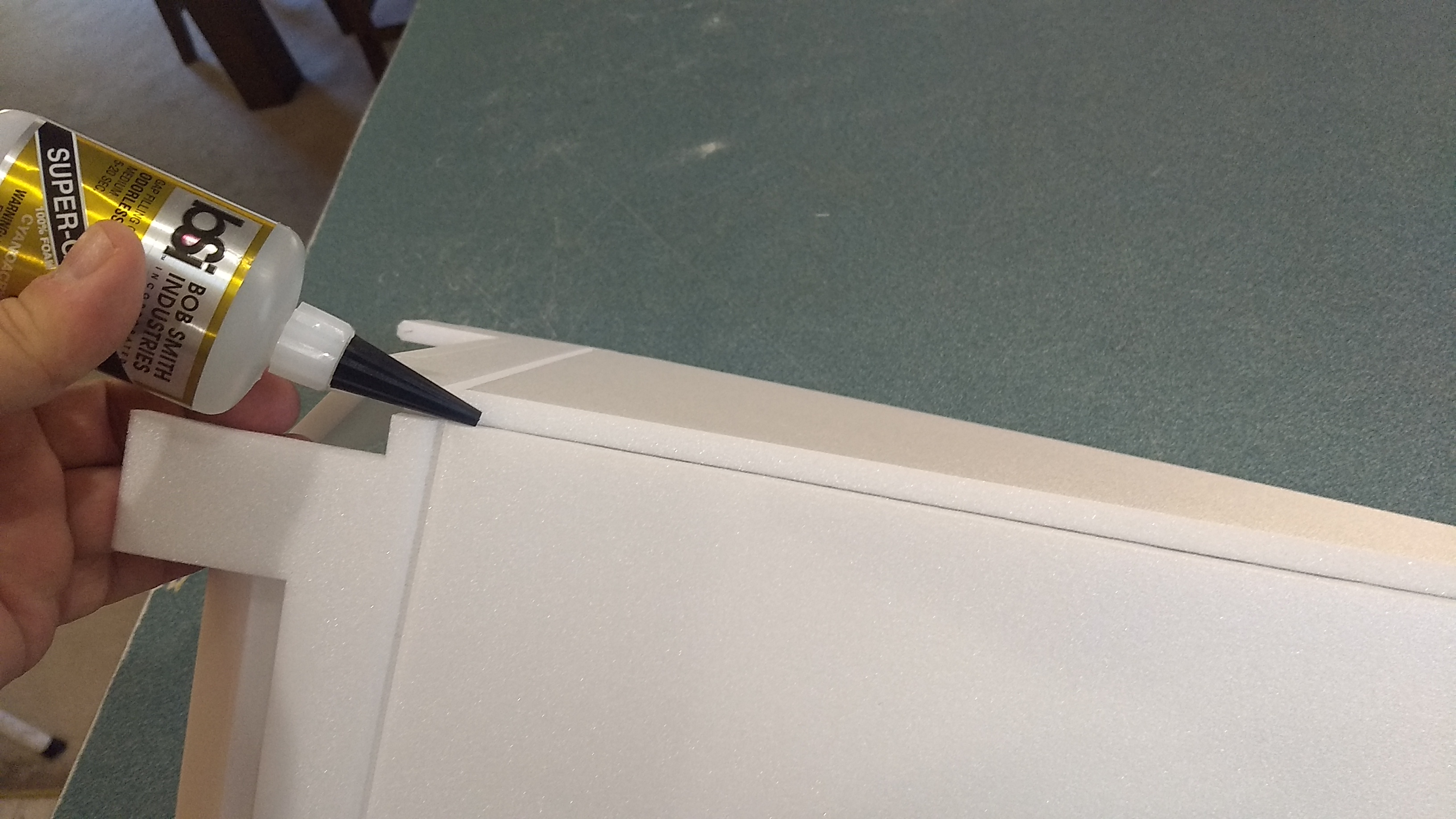
- Glue the wing center joint
-
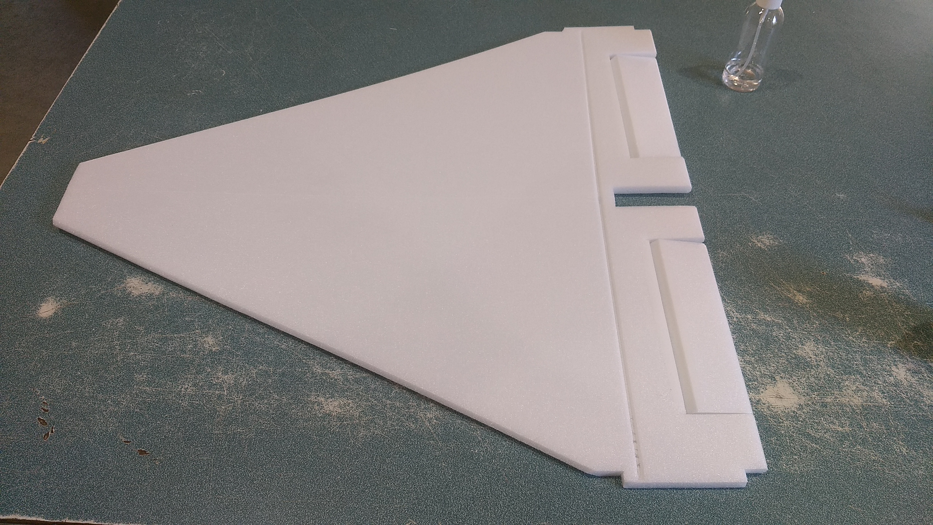
- Lay the wing flat till the glue dries
-
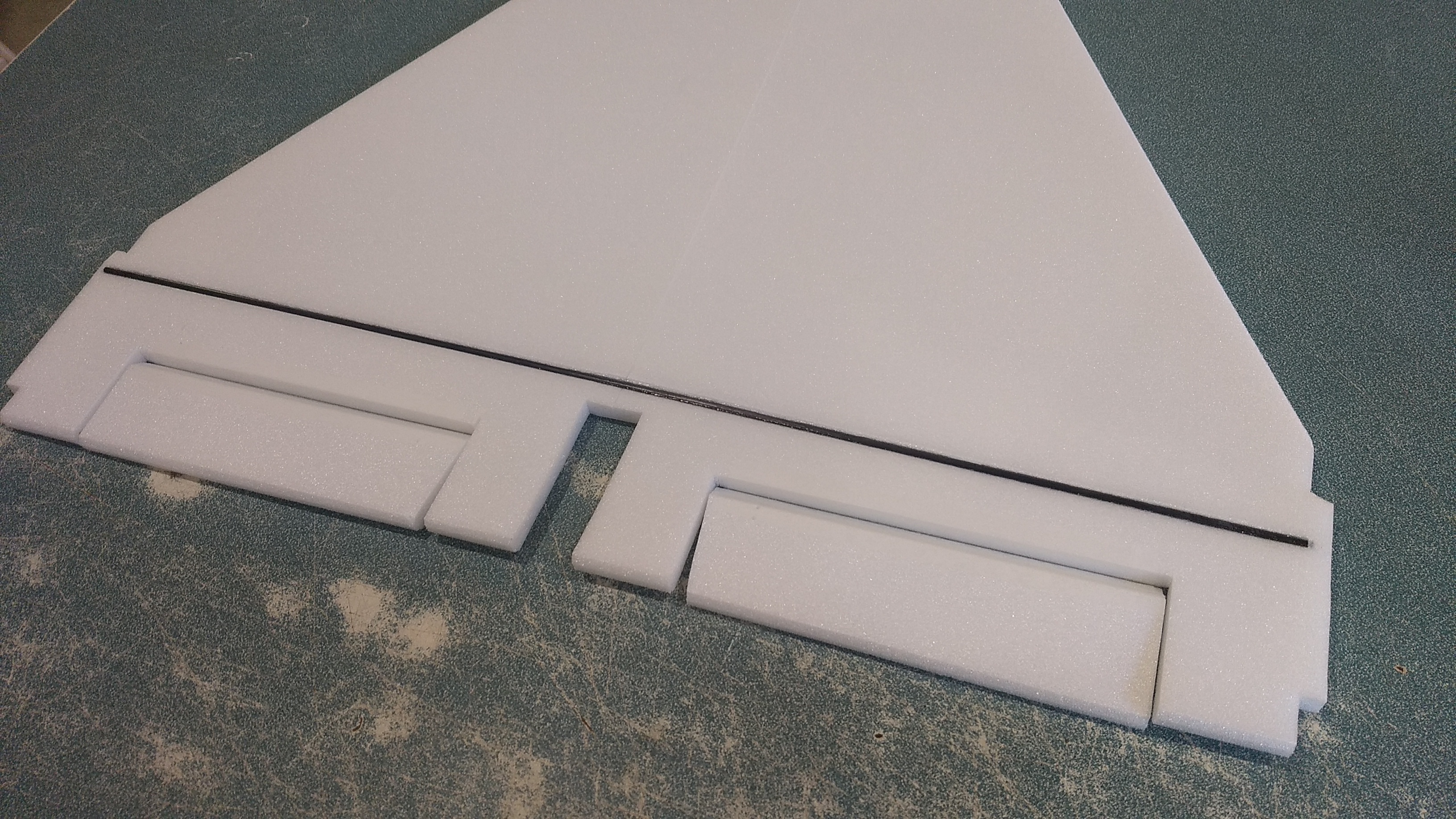
- Glue the spar
-
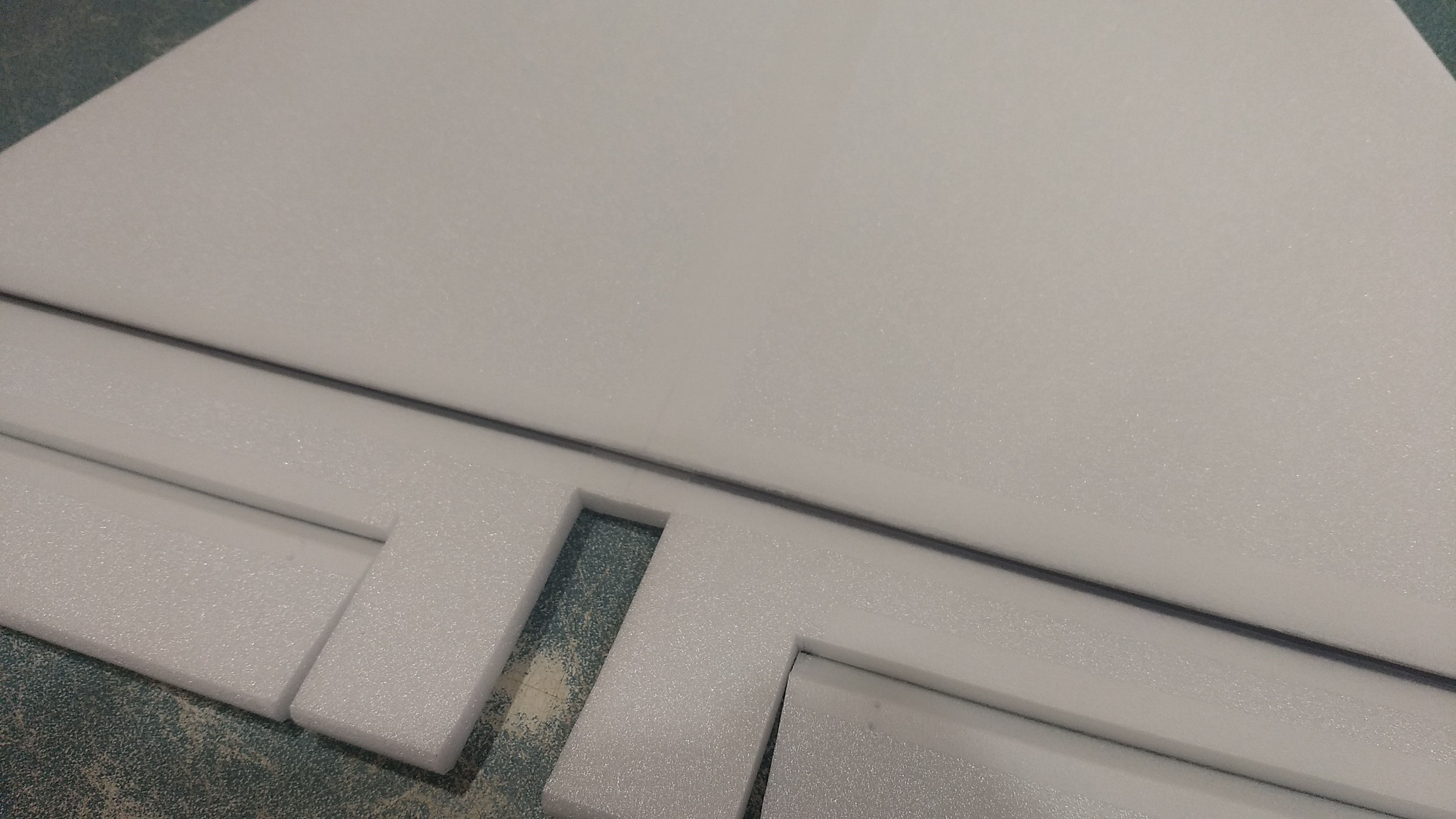
- Tape over the spar and center joint
-
- Insert coupler into the rear of the body tube to hold the shape then insert the wing and center it and tack glue, repeat at the front..
-

- Glue the wing in place and glue the coupler in the front
-
- Glue the vertical stab in place
-
- Test fit then insert the motor tube into the wing slot and below the vertical stab tab.
-
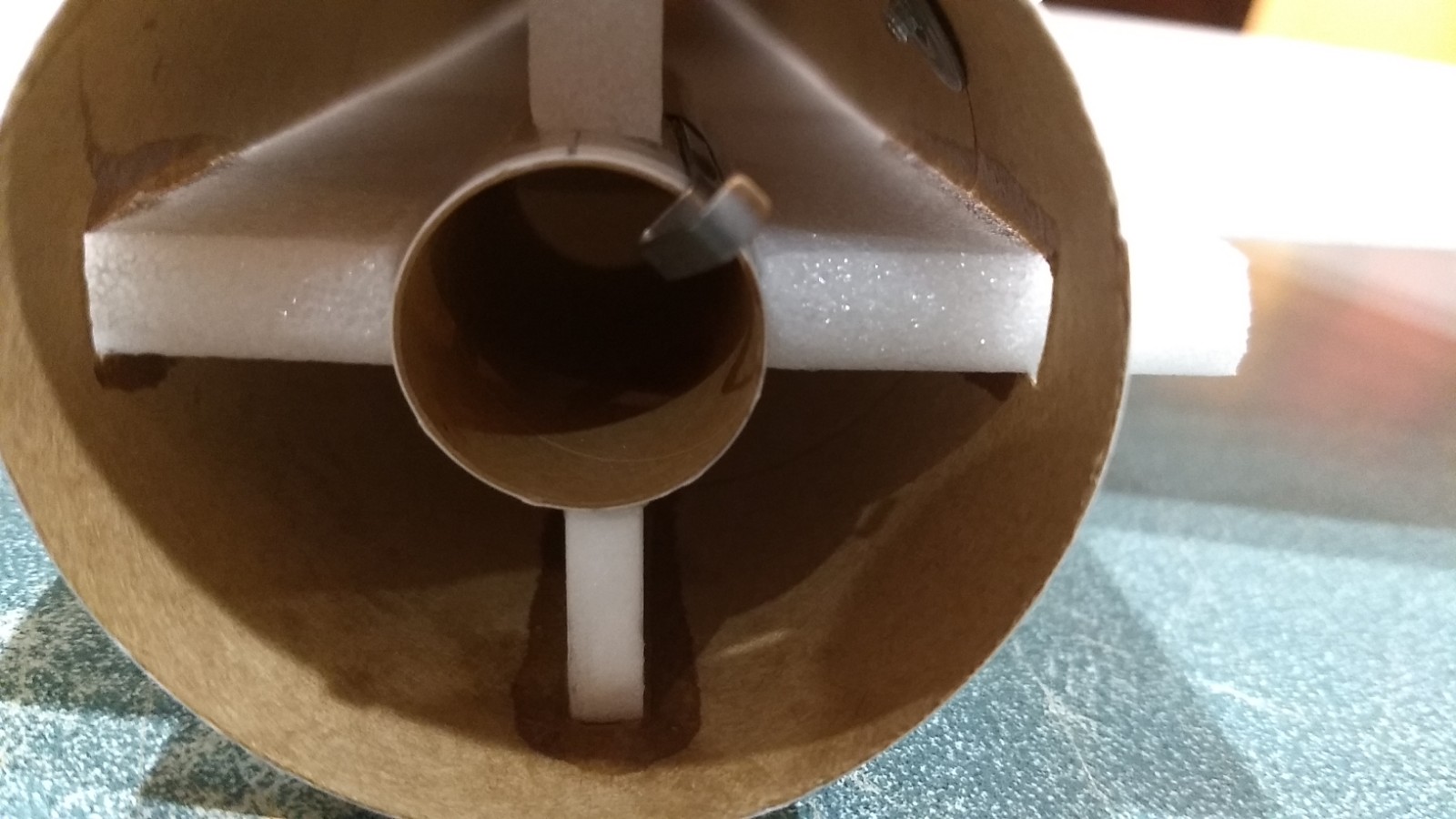
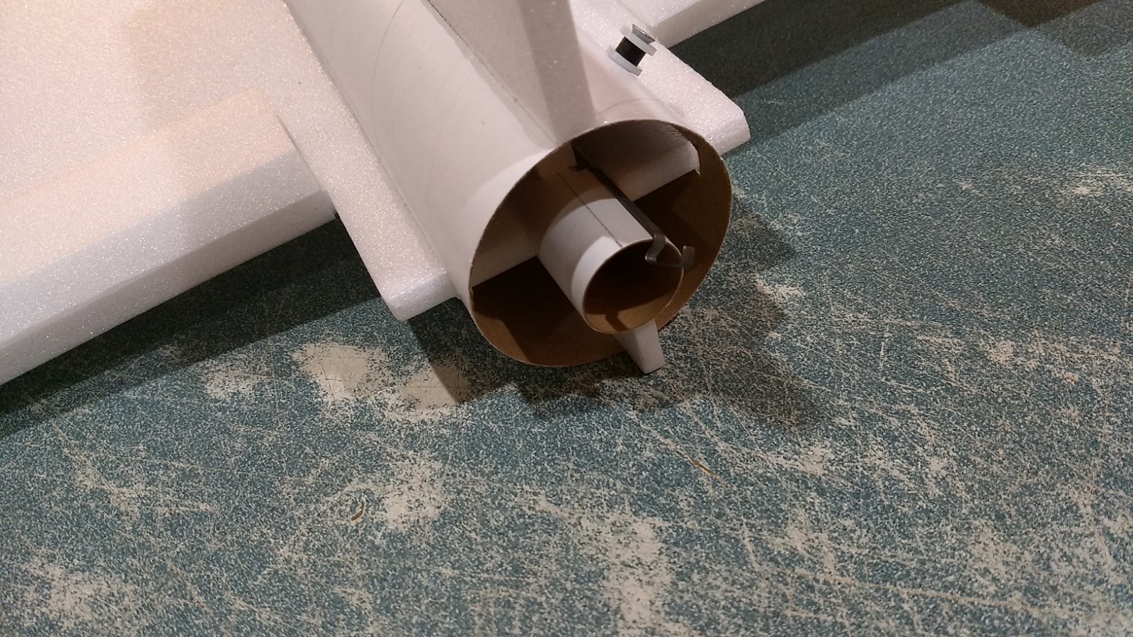
- Motor tube installed and glued in place, note it is recessed slightly
-
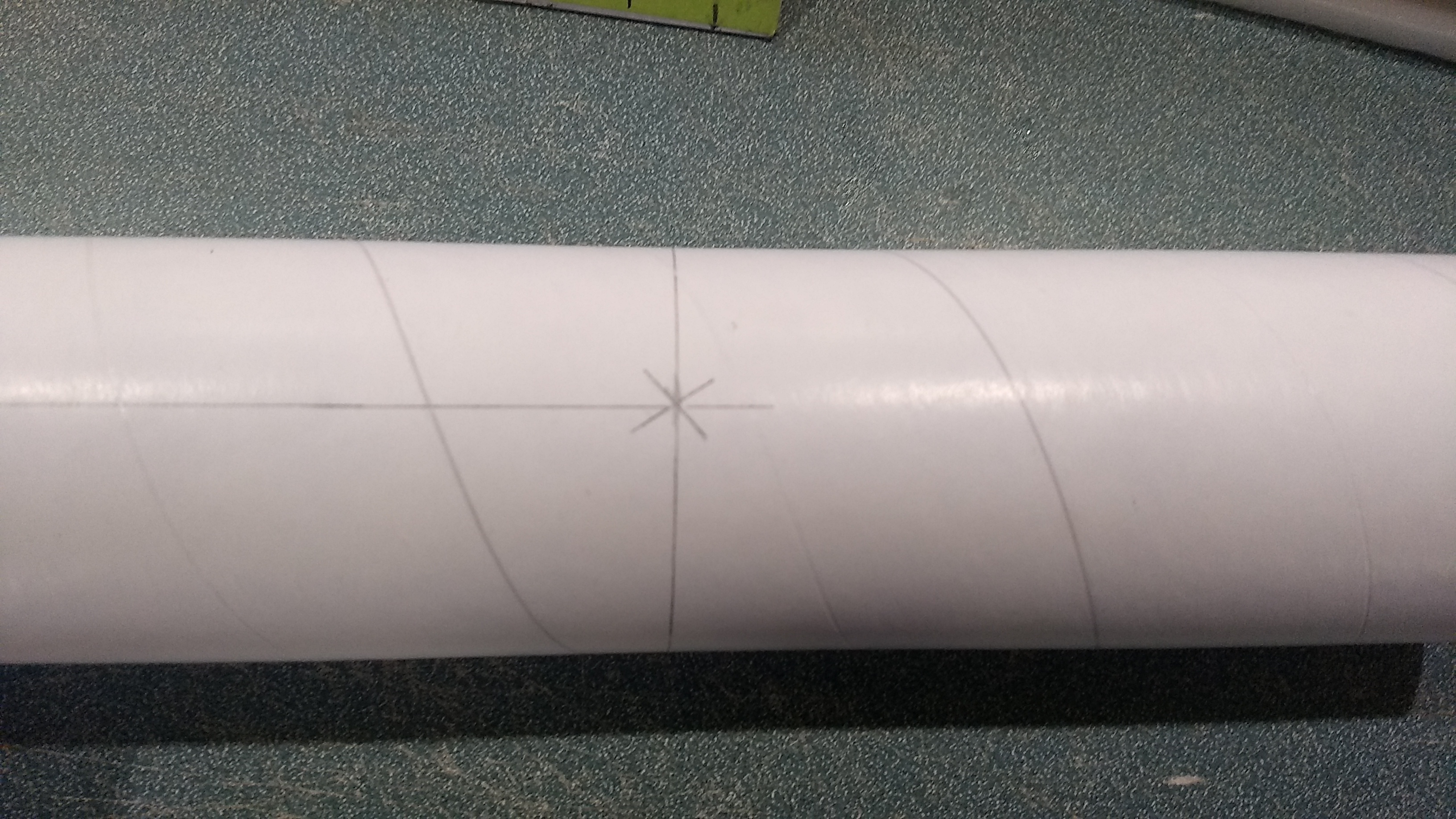
- glue the coupler into the rear tube then add the forward tube aligning the arrow marks on the bottom of the tubes.
-
- Wingstips installed
-

- Glue the bottom ventral fin in place.
-
- Glue the control horns into the pre-made holes on the bottom of each control surface, note the pushrod is closest to the body tube.
-

- Glue 3 canopy pieces together
-
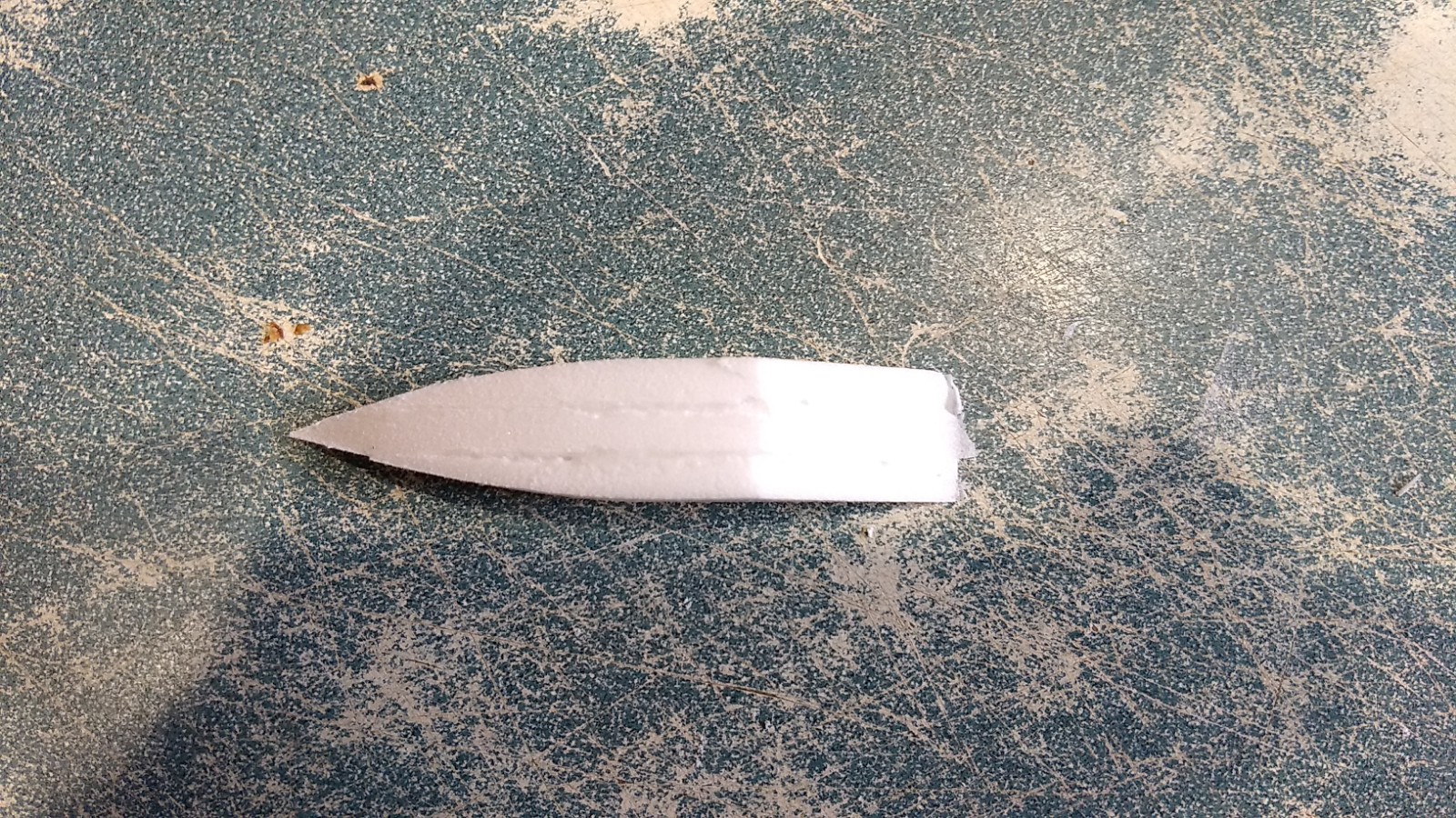
- Tapee the rear of the foam stack looking down from the top
-
- Bevel the front sides of the front of the canopy at an angle, then round the rear corners.
-
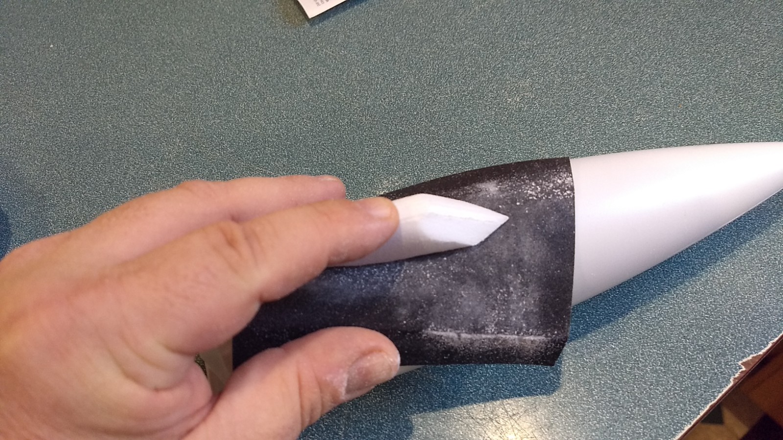
- Sand the bottom of the canopy to shape to match the nose cone.
-
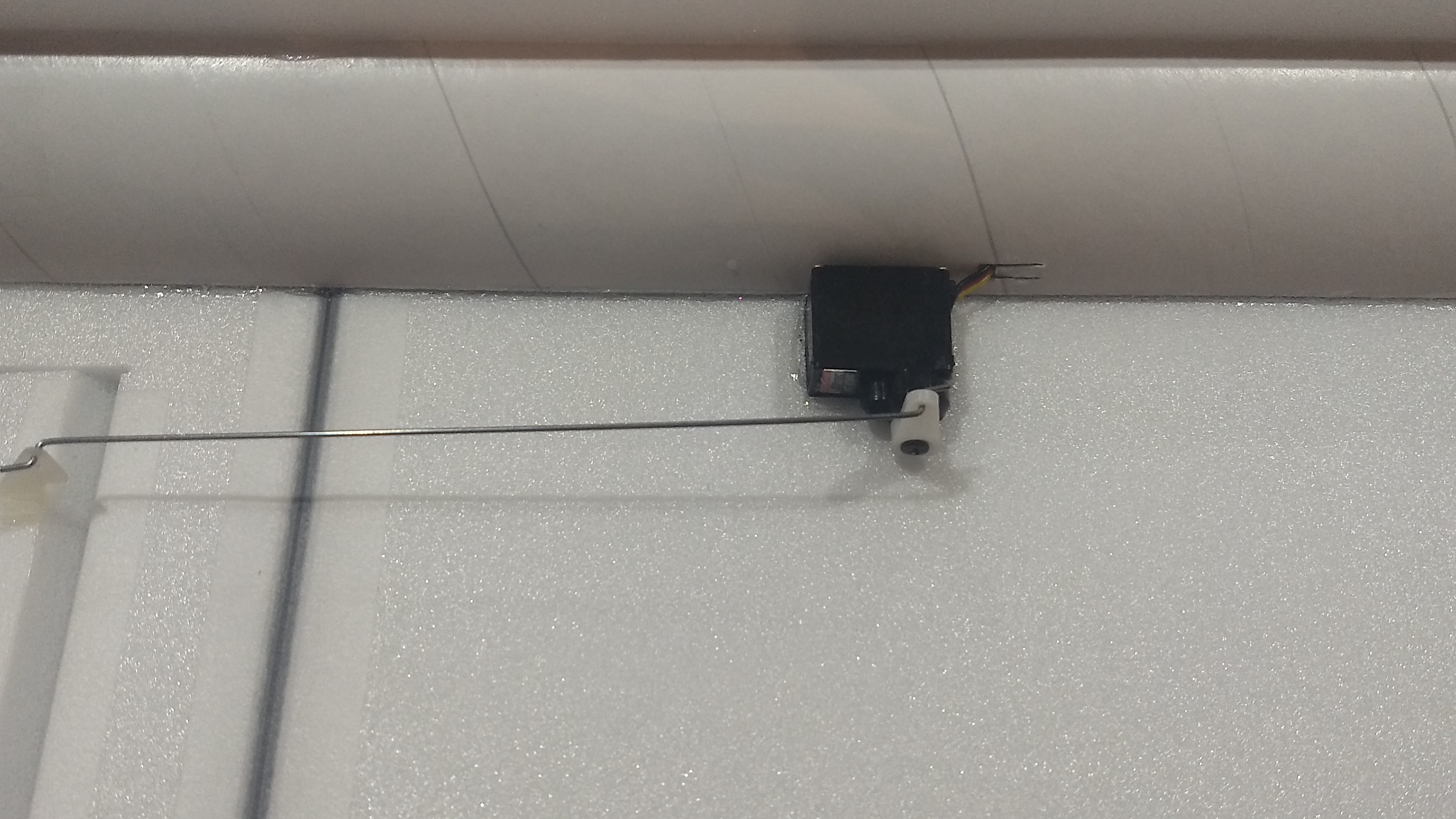
- Install the servos
-
- cut slots in the body tube and route the servo wires forward, then cover over the slots.
-
- Attach the receiver into the forward part of the body tube back far enough to clear the nose cone shoulder using velcro, the battery can be in the body or nose cone as needed for CG to avoid adding weight.
-

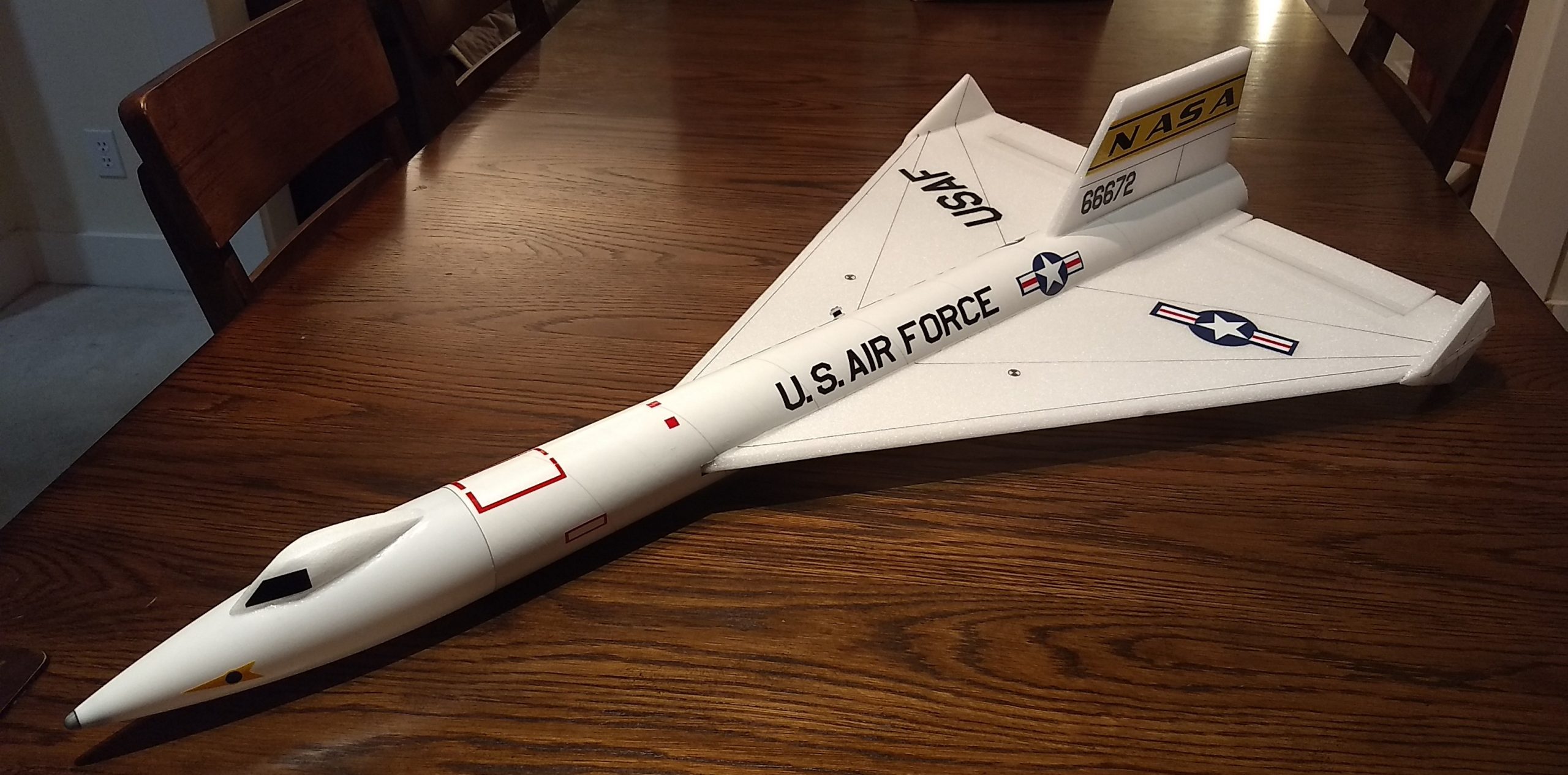
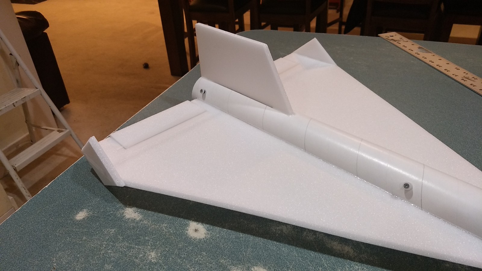
- Completed airframe

-
- Alternate black color scheme
-
- Example of stickershock decals
-
- White color scheme