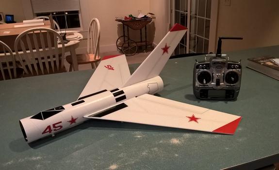
Wolverine Rocket Glider Kit
This model is styled after the old Estes Wolverine rocket, but with enlarged surfaces for gliding. This kit includes a white 3″ body tube pre-slotted, main wing/vertical stab spars and elevons installed. The wings are mid-mounted and use elevons for control. The canopy is printed on thick photo paper.
(This model requires two 12″ servo extensions. Please refer to the notes on items needed for completion and flying,then read the instructions completely before starting assembly. The assembly photos are for general reference but may not include every step in the manual. CG location for rocket flight should be 13 1/8″ from the front of the body tube.
Stickershock23.com carries decals or you can customize it!
Welcome to the world of rocket boosted radio control gliders. This is not a model for a novice RC pilot, but anyone who is comfortable with RC flying of a medium speed model should be fine. Read through the instructions, look at the photos and be sure you understand the step before commiting to cutting or glue.
Wolverine Rocket glider instructions
Identify all pieces, the kit should contain:
1 wing taped together
2 control horns with pushrods attached
1 Vertical Stabilizer
2 skids
1 Body Tube
Motor mount
Velcro(for battery and rx/bec attachment)
2 Rail buttons(2 washers, 2 collars, 2 screws, 2 rail button mounts) or 1 Launch lug
3M blenderm tape
1 wing spar.
Lead weight
Cardstock canopy
Notes before starting:
Reference to CA+ means foam safe CA+, normal CA+ will melt the foam! Normally you need to use accelerator to get the CA to set on the foam since there is nothing for it to soak into and activate.
You may use 220-320 grit sandpaper and a sanding block to slightly round the edges of the foam if you prefer that look. It will not markedly impact the flight performance either way. Be very careful and use a light touch, it is very easy to catch the foam on the edge of the paper and tear the foam. Do any sanding before assembly.
Epoxy is not needed in this model. Weight is critical and the model is designed for the thrust and flight loads. Weight in the rear end is bad and will require additional weight in the front of the model.
Assembly:
- Unfold the wing and glue the tape joint using CA+ and accelerator, make sure it is flat. Tape over the joint with blenderm tape.
- Test fit, then glue the spar in place in the slot on the bottom of the wing. Tape over the spar with blenderm tape once the glue has set.
- Test fit the wing in the slot in the body tube. Trim the slot as needed for a good fit. The slot is cut long to allow the wing to slide in and rotate into place. Center the wing in the body tube and make sure it is fully forward against the end of the slot. When satisfied, glue the wing to the body tube using foam safe CA+. The gap at the rear is normal.
- Use a tool/screwdriver to make a hole at each “RB” rail button mark and install the t nuts and rail buttons. The buttons are offset to the side so that they don’t get caught on anything when landing.
- Test fit the vertical fin in the slot, You may need to push the fin down slightly to get it to seat on the inside of the bottom of the tube, or trim the upper part of the fin to alow it to sit slightly lower and make full contact.
- Apply glue to the bottom of the fin and glue it to the inside of the fuselage, make sure the fin is perpendicular to the wing. Use the line on the inside of the body tube to aid alignment.
- Apply a fillet of CA+ to the inside and outside of the tube/fin joint.
- Glue the motor tube into the slot in the fin tab. Note the arrow on the motor tube, that should point towared the front of the model. Make sure it is centered left and right and front to back in the slot and that the motor clip will be free to move. Take your time to make sure it is straight, then run a fillet of CA+ at the motor mount/fin joints.
- If using a launch lug, glue it to the top of the wing where it hits the body tube so that the launch rod won’t interfere with the servo wires on the bottom of the wing.
- Cut out the canopy. Fold the canopy at each black line, fold so that the black lines will be in the underside of the canopy. Glue the tab at the front to form the shape. Once complete glue the canopy to the top of the model in the location you prefer, I glued mine about 1″ from the front.
- Install the control horns/pushrods into the elevons with CA+ in the pre-made holes. The pushrods should be on the inside of the control horn closest to the body tube. Apply CA+ on the top of the surface where the prongs poke through to lock them in place. Make sure these are installed securely.
- If desired and landing on a hard surface, you can install the skids on the bottom of the fuselage on the two lines marked, simply poke two holes for each skid, and install using CA+ to hold them in place.
The basic construction is now complete.
Radio Installation
Note: Your radio needs to be configured for Delta mixing, this means that the servo arms will move the same direction during elevator stick movement and opposite for aileron stick movement. Connect your servos to the receiver one in the aileron connection and one on the elevator connection and apply power. Use a servo arm at least 9/16” long and with holes small enough that there won’t be slop with the pushrod wire when installed. I use the hole furthest out on the servo arm, to maximize movement. On some servos there are a long two-ended servo arm, you can trim off one end if needed to get sufficient length. Zero out any trim settings on the transmitter. The model once the motor has burned out is nose heavy and flying wings lose pitch authority when nose heavy so you want as much up elevator travel for trim/flare as possible.
- Connect a servo to each pushrod, the servo wire should be closest to the center and the output shaft is outboard toward the wing tip. If the wire is too tight, you can use twist an exacto knife in the servo arm hole to make it larger, but be careful and do not make it too large. Once connected, tape each servo in place so that the control surfaces are centered. Flip the model right side up and look at it from the rear. Moving the transmitter stick back(up elevator) should move both elevons up. Moving the transmitter stick to the right should move the right elevon up and the left elevon down. If you can’t get the servo reversing to give you the right polarity try swapping aileron/elevator inputs to the receiver or turning the servos over and swapping the servo arms to the other side of the output shaft. If that is correct, continue.
- Flip the model upside down and supported. The servos may be attached to the model using double back servo mounting tape(not included) or by directly gluing the servo to the wing with CA+ or a small amount of epoxy. Double back servo tape can loosen over time and with exposure to heat, I prefer to glue the servo in place. With the radio still on, put a small amount of glue on the servo, being careful not to get any near the output shaft. And set it in place on the model keeping the control surface centered. Do the same to the other side. Make sure the glue is set before continuing. The servo and pushrod should be at 90 degrees to the hinge line so that it moves easily and fully. The servo should not be glued to the blenderm tape as it won’t adhere well. You can move the servo slightly left or right to avoid the tape.
- Flip the model back right side up. Make sure the control surfaces are centered, use trims if needed. Now measure the control surface movement. Full elevator movement should be 3/4” in each direction, aileron movement should be 1/2″ in either direction. Since the model will be nose heavy, elevator elevon movement helps to give sufficient authority during glide.
- If you have a flap/elevator mix you can program up elevator to a switch setting. The model needs approximately 1/8″ of downtrim for boost and 1/4” of up elevon during glide. If you can’t set the up elevator trim to a switch on your radio you’ll have to manually put in glide trim which is hard to do while flying the model.
- Attach a 12″ servo extension to each servo.
- Make a slot in the bottom side of the fuselage on each side and pass the servo wires through to the inside and toward the front.
- Attach the servo wires to the receiver and make sure they are going the right direction. Tape down the servo wires to the wing to secure them.
- Use the included Velcro to attach the receiver and battery to the model at the front inside bottom of the body tube. This allows you to be able to remove and replace the receiver if needed for repairs or for removing the servo wires. I left a small amount of room to put any nose weight in the bottom center of the fuse at the front when balancing.
- Insert your heaviest loaded rocket motor into the motor mount
- Support the model at the balance point indicated for boost. I use two pencils with the eraser pointed up and held in place with a small hand vice. Place the model upside down on the pencil erasers on the balance point indicated in the kit spec sheet. Use the included lead weight at the front of the model to balance it.
- Do not try to fly the model with it balancing it behind this point. The adage is, a nose heavy model flies poorly, a tail heavy model flies once.
- I used vinyl for the trim colors on my model. With the vinyl from stickershock23 it helps once applied to use a hair dryer on hot to soften the material and then push it down onto the model with a towel. It helps it conform and stick much better.
- Use a black sharpie to add panel lines if desired.
- Re-install the receiver and battery
Flying: See the Instruction/Information link at the top for flying instructions Note this model uses a slight down trim for boost unlike the other models which use neutral controls for boost. Be ready on the first few flights to keep the model straight till you have the trims set perfectly.