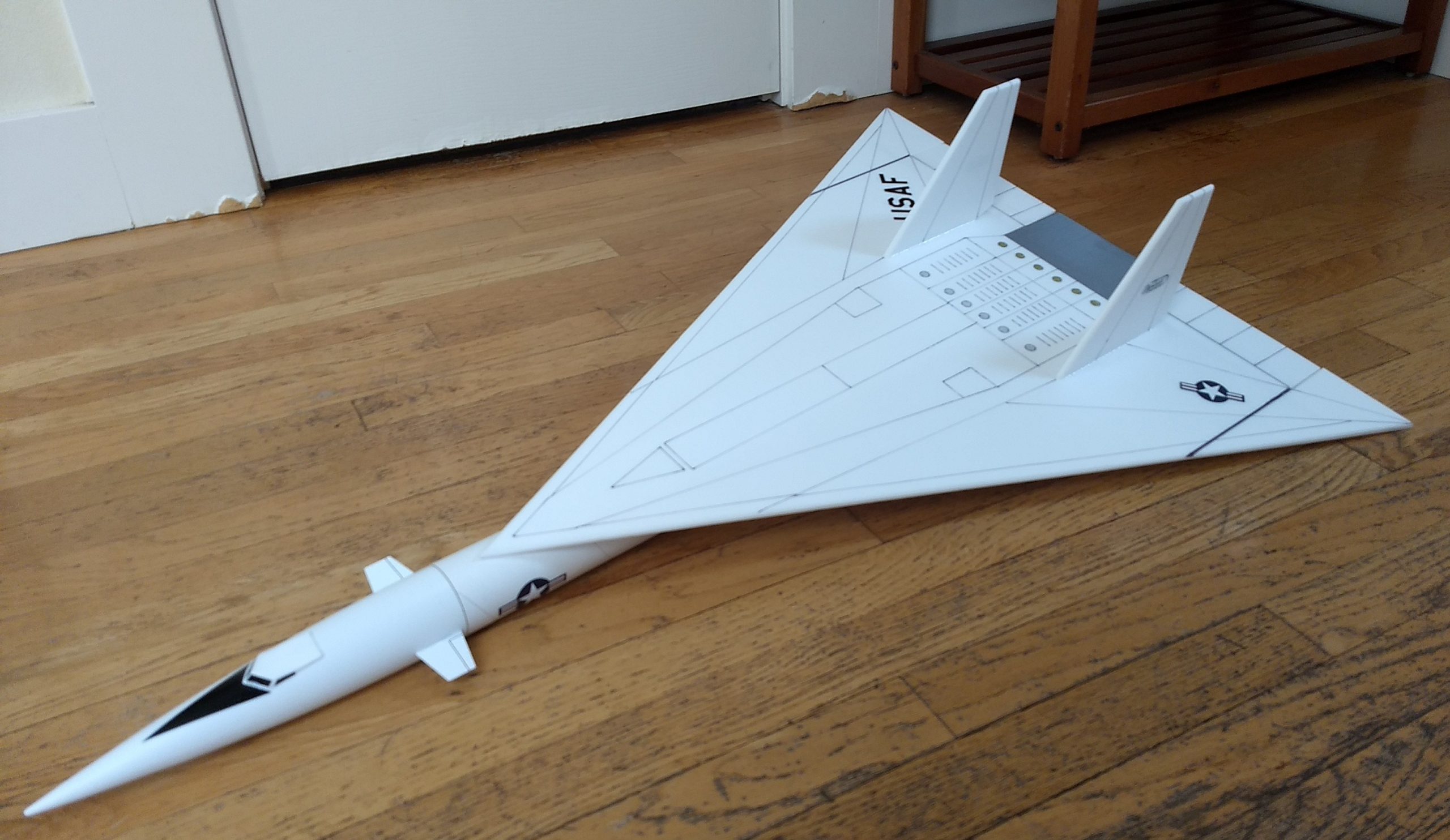
The Valhalla RC Rocket glider kit. Styled after the Mach 3+ XB-70 Valkyrie Bomber. It has a high mounted delta wing, double vertical stabilizers and nose mounted forward canards. It has a light wing loading giving it a very nice glide and easy/stable boost. It comes with a plastic nose cone, 2″ white tubing for the body and depron wing and tail surfaces. Construction is very simple and takes about an hour. You will need two 10 gram type servos, two 18″ servo extensions, a receiver, and a small 500mah single cell lipo battery. You will need a transmitter with delta or elevon mixing. Length 36.5″ length, 23.5″ wingspan, 10.8 oz rtf. High quality cut vinyl decals will are available HERE:
Please refer to the General instructions link above, then read these instructions completely before starting assembly. The assembly photos are for general reference but may not include every step in the manual.
CG location for rocket flight: Right at the joint between the two body tubes, ~13.5″ forward from the rear of the body tube.
Welcome to the world of rocket boosted radio control gliders. This is not a model for a novice RC pilot, but anyone who is comfortable with RC flying of a medium speed model should be fine. Read through the instructions, look at the photos and be sure you understand the step before commiting to cutting or glue.
Valhalla Rocket glider instructions
Identify all pieces, the kit should contain:
1 wing taped together
2 wing spars(carbon fiber)
2 pushrods/control horns
2 vertical stabilizers
2 long Foam wing reinforcing strips
2 short foam motor mount reinforcing strips
2 Body Tubes
Motor mount
Velcro(for battery and rx/bec attachment)
2 Rail buttons with t nuts/screws(may be installed in tube for you)
3M blenderm tape
Lead weight
Spare depron
Notes before starting:
Reference to CA+ means foam safe CA+, normal CA+ will melt the foam! Normally you need to use accelerator to get the CA to set on the foam since there is nothing for it to soak into and activate.
I’ve found beveling the edge with an exacto knife is easier than trying to sand, simply use a thin straight edge and cut a 1/16″ wide bevel on the leading and trailing edges on both sides of the wing and stabilizers before gluing them to the model.
Epoxy is not needed in this model. Weight is critical and the model is designed for the thrust and flight loads. Weight in the rear end is bad and will require additional weight in the front of the model.
Assembly:
- Unfold the wing and glue the front and rear tape joints using CA+ and accelerator, make sure it is flat
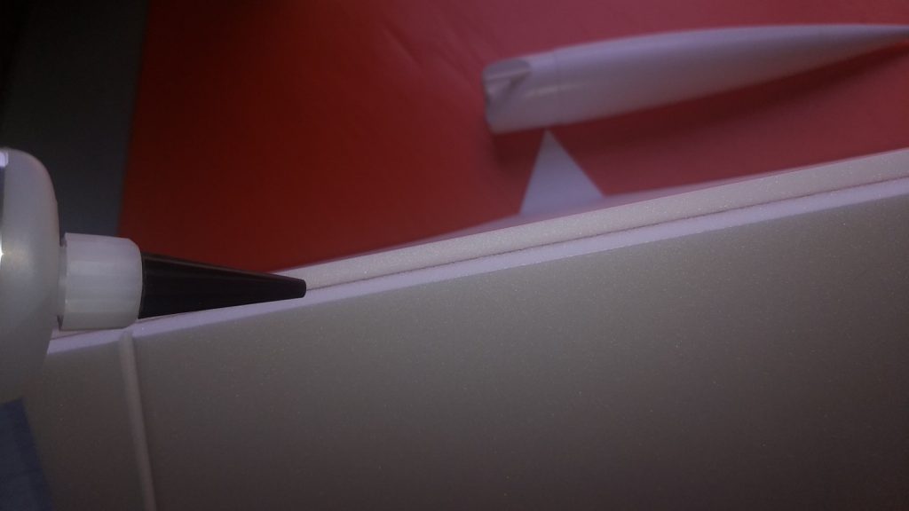
- Glue the two wing spars in the pre-slotted areas on the bottom of the wing with CA+ and then tape over the two spars with the included blenderm tape.
- Install the front and rear rail buttons in the pre-cut holes in the rear body tube if not already done for you.
- Glue the thrust ring into the motor tube.
- Glue the other body tube to the coupler, making sure to keep the wing alignment line on the two tubes aligned.
- One tube will have a line inside the tube on one end, that is the rear of the model and the inside line is for the motor tube alignment.
- Glue the motor tube inside the rear of the body tube on the alignment line marked on the inside, be sure the motor tube is aligned straight with the body tube. You can look down the front of the body tube and see if the motor tube is straight. There are no centering rings needed or desired because you may need to reach wiring or weight at the rear of the model.
- Glue two short foam reinforcing strips on either side of the motor tube and add a fillet of CA+ to help support the motor tube.
- Lay the wing upside down on a flat surface. Using CA+ foam safe glue glue the body tube to the wing. Use the pencil marks on the body tube as a guide at the front and back. Make sure the tube is centered and the rear of the wing is even with the rear of the body tube with the motor tube installed. The rail buttons will be toward the rear of the model and the rail buttons will be pointed up.
- Apply CA+ foam safe glue to one of the reinforcing strips and glue one on each side of the wing/body tube joint. The reinforcing strip should align with the rear of the model but won’t go all the way to the front of the wing. This piece is there to give more gluing surface to the wing/body tube. If you push in too hard on these strips it can cause the body tube to rotate slightly, so pay attention. Once they are in place put a fillet of CA+ on both the wing and body tube joints.
- Glue the vertical stabs to the wing using the tabs. Make sure they are 90 degrees to the wing, are straight and reinforce with a slight fillet.
- Glue the two pushrods/horns into the bottom of each surface in the pre-made holes, note the pushrods will be closest to the body tube, there is a left and right assembly, then put glue on the top of the prongs on the top of each surface to lock them in place.
- Glue the two canards into the slots in the nose cone. Make sure they are level with each other when looking from the front. I used foam safe CA and then put a fillet on each side.
- Shape and then sand the bottom of the cockpit so it matches the nose cone, then glue the cockpit to the nose cone about 3-4″ back from the tip of the cone.
- The kit comes with the straight wing tips used for takeoff and landing, if you wish you can cut the wingtips off just outboard of the spar and sand a 45 degree angle on the wingtip root and glue it back on to the wing tip for that bent down look of the Valkyrie, don’t bend down more than 45 degrees or they will drag on the ground when landing. The main kit picture shows the wingtips bent down in this manner.
The basic construction is now complete.
Radio Installation
Note: Your radio needs to be configured for Delta mixing, this means that the servo arms will move the same direction during elevator stick movement and opposite for aileron stick movement. Connect your servos to the receiver one in the aileron connection and one on the elevator connection and apply power. Use a servo arm at least 9/16” long and with holes small enough that there won’t be slop with the pushrod wire when installed. I use the hole furthest out on the servo arm, to maximize movement. On some servos there are a long two-ended servo arm, you can trim off one end if needed to get sufficient length. Zero out any trim settings on the transmitter. The model once the motor has burned out is nose heavy and flying wings lose pitch authority when nose heavy so you want as much up elevator travel for trim/flare as possible.
- Connect a servo to each pushrod, the servo wire should be closest to the center and the output shaft is outboard toward the wing tip. If the wire is too tight, you can use twist an exacto knife in the servo arm hole to make it larger, but be careful and do not make it too large. Once connected, tape each servo in place so that the control surfaces are centered. Flip the model right side up and look at it from the rear. Moving the transmitter stick back(up elevator) should move both elevons up. Moving the transmitter stick to the right should move the right elevon up and the left elevon down. If you can’t get the servo reversing to give you the right polarity try swapping aileron/elevator inputs to the receiver or turning the servos over and swapping the servo arms to the other side of the output shaft. If that is correct, continue.
- Flip the model upside down and supported. The servos may be attached to the model using double back servo mounting tape(not included) or by directly gluing the servo to the wing with CA+ or a small amount of epoxy. Double back servo tape can loosen over time and with exposure to heat, I prefer to glue the servo in place. With the radio still on, put a small amount of glue on the servo, being careful not to get any near the output shaft. And set it in place on the model keeping the control surface centered. Do the same to the other side. Make sure the glue is set before continuing. The servo and pushrod should be at 90 degrees to the hinge line so that it moves easily and fully.
- Flip the model back right side up. Make sure the control surfaces are centered, use trims if needed. Now measure the control surface movement. Full elevator movement should be 1” in each direction, aileron movement should be 1/2″ in either direction. Since the model will be nose heavy, extra elevon movement helps to give sufficient authority during glide.
- If you have a flap/elevator mix you can program up elevator to a switch setting. The model needs approximately 1/4” of up elevon during glide and slightly less than1/8″ of down trim for boost. If you can’t set the up elevator trim to a switch on your radio you’ll have to manually put in boost and glide trim which is hard to do while flying the model.
- Attach an 18″ servo extension to each servo.You just need to be able to route the wire to the front of the tube to attach it to the receiver.
- Make a slot in the body tube just ahead of the servo and pass the wires through to the inside and toward the front.
- Attach the servo wires to the receiver and make sure they are going the right direction. Tape down the servo wires to the wing and tape over the slot in the body tube.
- Use the included Velcro to attach the receiver 2″ from the front of the body tube(or enough to allow the wires to clear the shoulder of the nose cone). This allows you to be able to remove and replace the receiver if needed for repairs or for removing the servo wires. I attached the battery inside the nose cone on the shoulder.
- If you paint the model, make sure you test it on scrap foam first.
- If you are going to paint the model, you can mask off the servos. Make sure no paint will get on the servo output arm. Make sure to test the paint on a scrap piece first to ensure it won’t melt the foam. I use Model Master(testors) or testors enamel small rattle cans for painting directly on the foam.
- I used decals from stickershock23 and it helps once applied to use a hair dryer on hot to soften the material and then push it down onto the model with a towel. It helps it conform and stick much better.
- Use a black/silver sharpie pens to add panel lines if desired,
- Re-install the receiver and battery
- Insert your heaviest loaded rocket motor into the motor mount
- Support the model at the balance point indicated for boost. I use two pencils with the eraser pointed up and held in place with a small hand vice. Place the model upside down on the pencil erasers on the balance point indicated in the kit spec sheet. Use the included lead weight to balance it. Do not try to fly the model with it balancing it behind this point. The adage is, a nose heavy model flies poorly, a tail heavy model flies once
Flying: See the General Instruction/Information link at the top for flying instructions Note, my prototype needed a small amount of down trim on boost and as it gained speed arced back up vertical. Be ready on the first few flights to keep the model straight till you have the trims set perfectly for boost and glide.
Glue rear fold joint and lay flat. 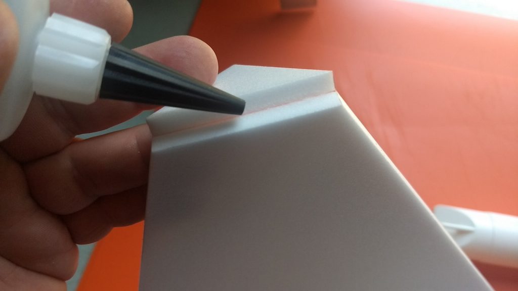
Glue forward joint. 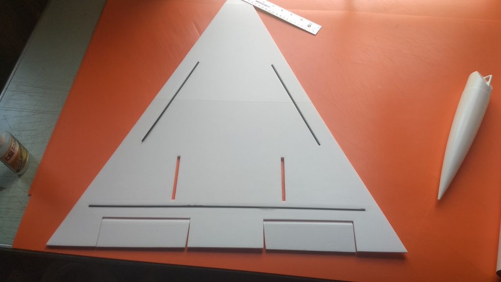
Install forward spars and tape over spars and center joint. 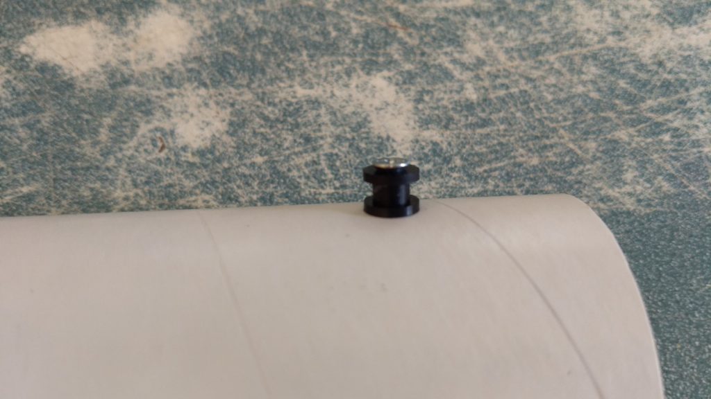
Install the front and rear rail buttons. 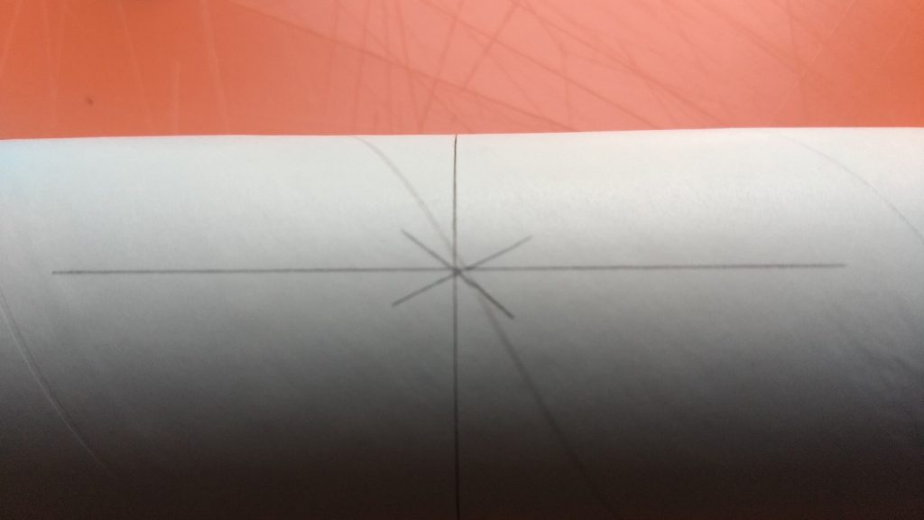
Join Body Tubes keeping arrow marks aligned 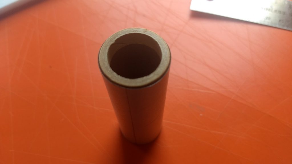
Glue in thrust ring if using single use motors 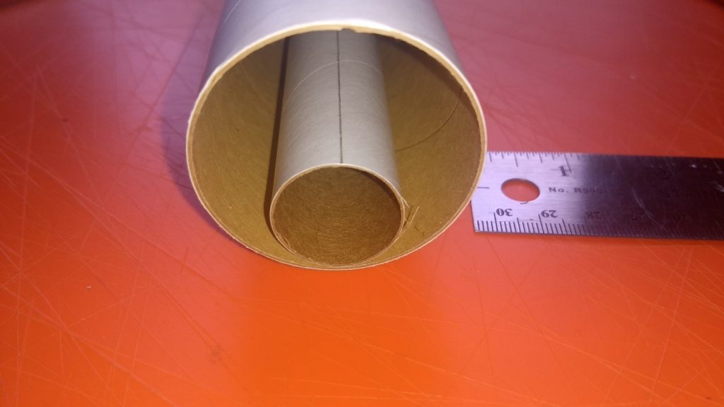
Glue motor tube in rear of body on alignment line. 
Add motor reinforcing strips on either side of motor mount. 
Glue body to wing. 
Add reinforcing strips on either side of the wing. 
Vertical Stabs Installed. 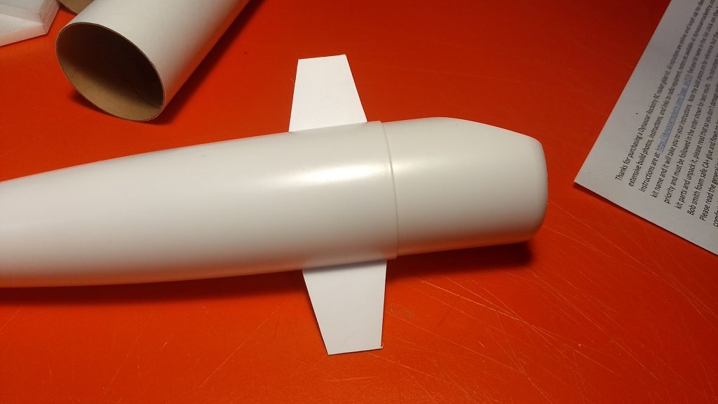
Glue in Canards 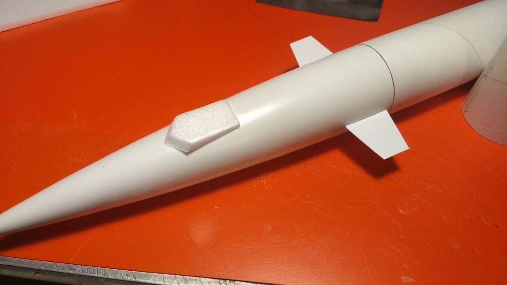
Fit and glue on cockpit 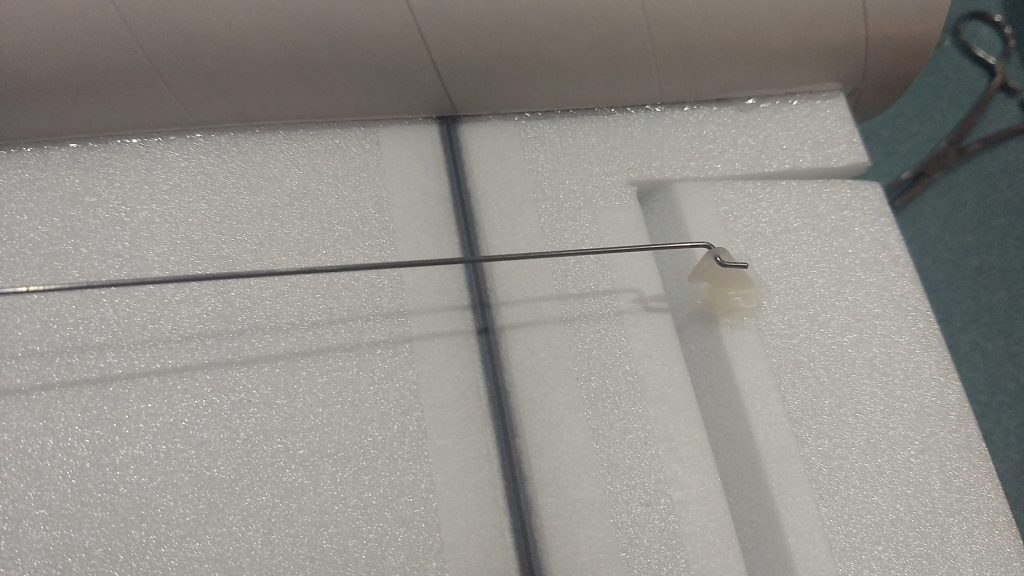
Control horn and pushrod glued to bottom of control surface 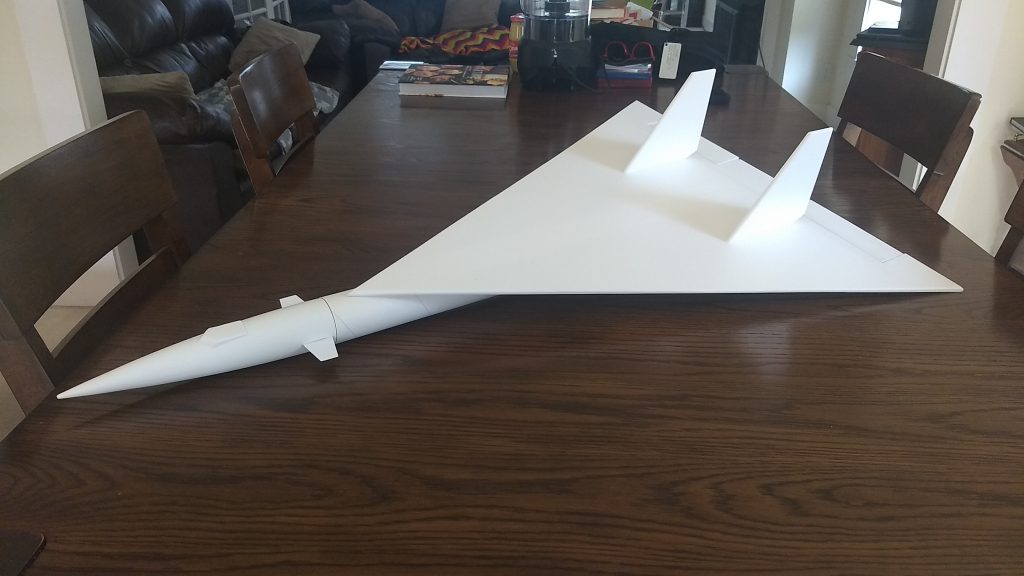
Completed Airframe 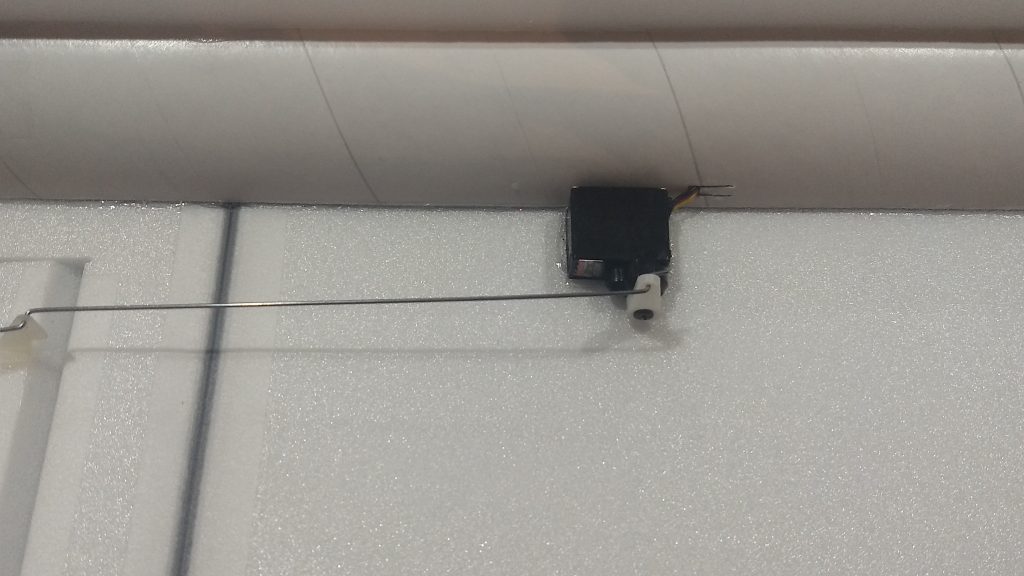
Servo glued in place next to fuselage. 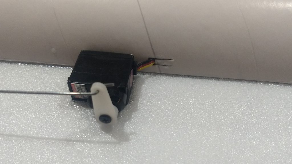
Servo wire routed via slot in the tube to the front of the model. 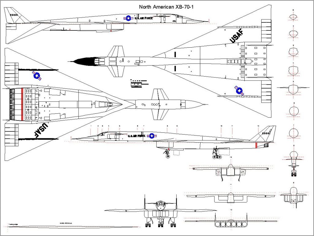
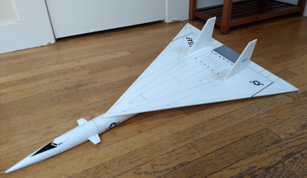
Completed Model 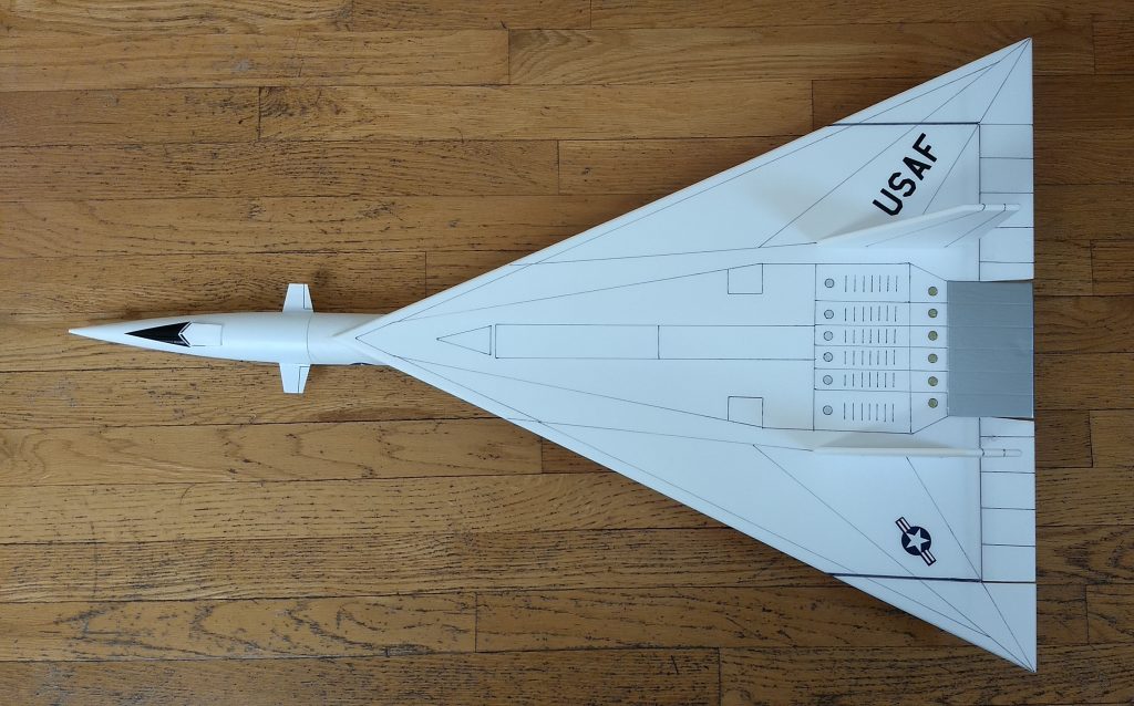
Top View 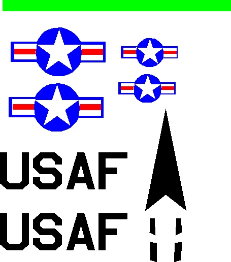
Example of Stickershock Markings 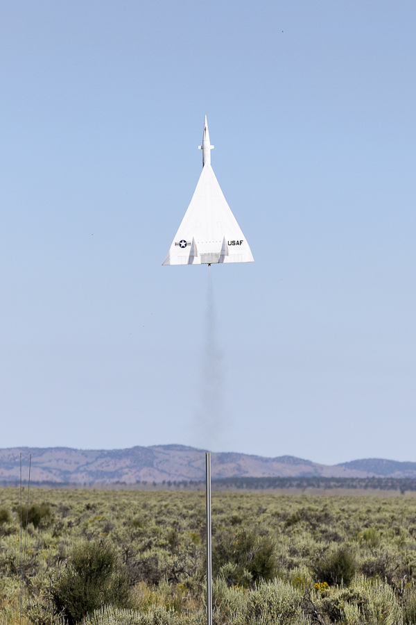
Taking Flight 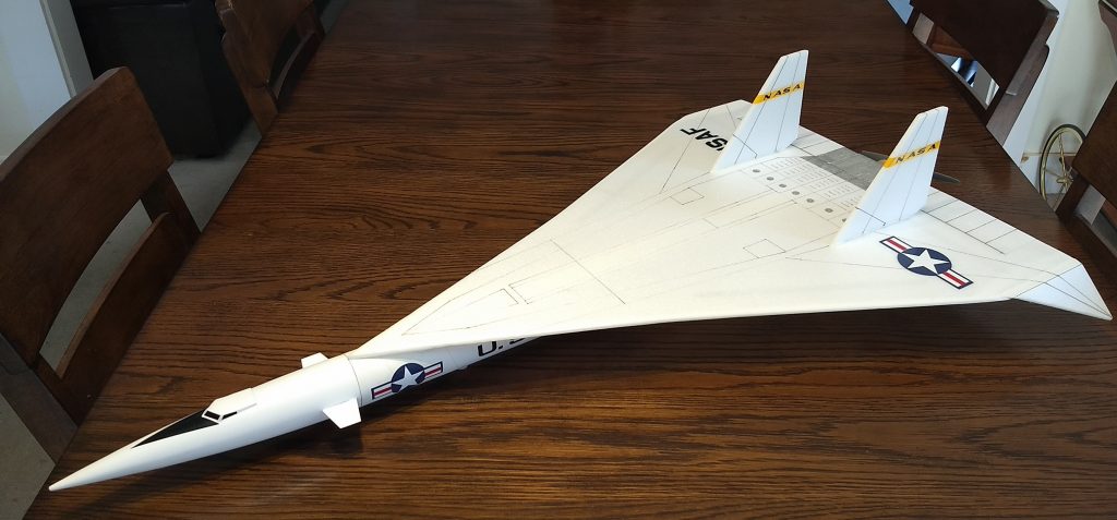
Completed model with optional bent down wingtips