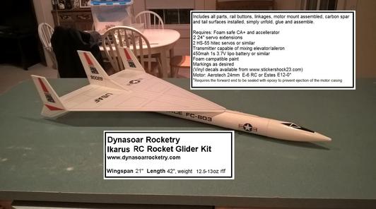
Ikarus Rocket Glider Kit
The Ikarus is available in two different versions, a futuristic high speed reconaisance plane, or an X-15-3 Delta configuration style that was proposed in the 60’s. It has a high mounted delta wing with a light wing loading giving it a very nice glide and easy/stable boost. It comes with a plastic nose cone and bt-80 tubing for the body and depron wing and tail surfaces. Construction is very simple and takes about an hour. You will need two 10 gram type servo, two 18-24″ servo extensions, a receiver, and a small 250-500mah single cell lipo battery. You will need a transmitter with delta or elevon mixing. Both versions are identical in construction and flight, just the shape of the tail/wingtips are different. The recon version shown used the same markings as the IntR/Ceptor kit and the X-15-3 version used the standard X-15 markings both from stickershock23.
Please refer to the notes on items needed for completion and flying, then read the instructions completely before starting assembly. The assembly photos are for general reference but may not include every step in the manual.
CG location for rocket flight 14 5/8″ forward from the TE of the wing
(Due to the CG location, and the fact that the equipment is mounted inside a body tube with no cooling airflow, it would be difficult to attach a battery and speed control in an optimum/accessable location, so it is not recommended to fly this using the electric adapter)
Welcome to the world of
rocket boosted radio control gliders. This is not a model for a novice RC
pilot, but anyone who is comfortable with RC flying of a medium speed model
should be fine. Read through the instructions, look at the photos and be
sure you understand the step before commiting to cutting or glue.
Ikarus Rocket glider instructions
Identify all pieces, the kit should contain:
1 wing taped together
2 wing spars(carbon fiber)
2 pushrods
3 Vertical Stabilizers
2 Foam wing reinforcing strips
2 foam motor mount reinforcing strips
2 Body Tubes
Motor mount
Paper canopy
Velcro(for battery and rx/bec attachment)
2 Rail buttons or 1 Launch lug
3M blenderm tape
Lead weight
Spare depron
Optional(if ordered):
Electric motor adapter
Notes before starting:
Reference to CA+ means foam safe CA+, normal CA+ will melt the foam!
Normally you need to use accelerator to get the CA to set on the foam since
there is nothing for it to soak into and activate.
You may use 220-320 grit sandpaper and a sanding block to slightly round the
edges of the foam if you prefer that look. It will not markedly impact
the flight performance either way. Be very careful and use a light touch,
it is very easy to catch the foam on the edge of the paper and tear the foam.
Do any sanding before assembly.
Epoxy is not needed in this model. Weight is critical and the model is
designed for the thrust and flight loads. Weight in the rear end is bad
and will require additional weight in the front of the model.
Assembly:
- Unfold the wing and glue the tape joints using CA+ and accelerator, make sure it is flat
- Glue the two wing spars in the pre-slotted areas on the bottom of the wing with CA+ and then tape over with the included blenderm tape.
- Body Tubes. One of the tubes has a line that does not go all the way to the front, that is the forward tube, we’ll use that later. The other tube will have a line inside the tube on one end, that is the rear tube and the inside line is for the motor tube alignment.
- Glue the the coupler halfway into the rear tube into the end marked “coupler”. Use glue sparingly, you don’t need a lot of strength here as the wing will support the tubes as well.
- If using rail buttons, use a tool or drill make holes in the tube at the “x” marked “RB”. Insert a T nut into each hole from the inside and then install the rail button and screw. You don’t need to tighten them down really tight, just enough to hold them in place. In early models there is a single rail button mark on each body tube, on later models the two rail buttons locations are marked on the rear tube only.
- Glue the front tube to the rear tube at the coupler, make sure to keep the line on outside of the two tubes aligned.
- Insert the two pushrods into the outermost hole in the control horn. Do this from the inboard side of the horn, do it now because it is difficult to do this once the wing is glued to the tube. You will need to twist the pushrod to get it to go into the hole, be careful and don’t poke your finger, go slowly so that it fits snugly.
- Lay the wing upside down on a flat surface. Using CA+ foam safe glue glue the body tube to the wing. Use the pencil marks on the body tube as a guide. You can use the vertical stab cutout on the wing to see that the rear is aligned and use the front of the wing as well. Make sure the tube is not rolled to one side or the other.
- Apply CA+ foam safe glue to one of the reinforcing strips and glue one on each side of the wing/body tube joint. The reinforcing strip should align with the rear of the model but won’t go all the way to the front of the wing. This piece is there to give more gluing surface to the wing/body tube. If you push in too hard on these strips it can cause the body tube to rotate slightly, so pay attention. Once they are in place put a fillet of CA+ on both the wing and body tube joints.
- Glue the motor tube at the top of the body tube right underneath the wing and aligned with the end of the body tube. The model is upside down now so it will be the at the bottom of the tube in this orientation. Make sure the motor tube is aligned straight with the body tube. There are no centering rings needed or desired because you may need to reach wiring or weight at the rear of the model. The motor tube hook is only taped on one side, you want to be sure you don’t glue to the tape or hook, this is done so that you can glue the paper motor tube directly to the body tube without the tape in the way.
- Glue the two short reinforcing strips on either side of the motor tube and add a fillet of CA+ to help support the motor tube.
- Glue the vertical stab to the wing using the tab. Make sure it is 90 degrees to the wing, is straight and reinforce with a slight fillet.
- Glue two wing tips to
the wing, the larger suface points “up” Make sure they are
perpendicular to the wing and put a small fillet to reinforce the joint.
- If you are using a launch lug I recommend putting it at the wing/body tube joint so that it will clear any wiring/servo placement, or on the side of the tube about midway down.
- Cut out the canopy. Fold the canopy at each black line, fold so that the black lines will be in the underside of the canopy. Glue the tab at the front to form the shape. Once complete glue the canopy to the top of the model on the nose cone.Trim as needed to fit.
The basic construction is now complete.
Radio Installation
Note: Your radio needs to be configured for Delta mixing, this means that
the servo arms will move the same direction during elevator stick movement and
opposite for aileron stick movement. Connect your servos to the receiver
one in the aileron connection and one on the elevator connection and apply
power. Center the servo output arm by removing the screw and
pulling the output arm off and re-installing it as close to center as possible
and re-install the screw. Use a servo arm at least 9/16” long and
with holes small enough that there won’t be slop with the pushrod wire when
installed. I use the hole furthest out on the servo arm, to maximize
movement. Zero out any trim settings on the transmitter. With the model
upside down and supported, lay a servo on each side near the control
surface. You want the servo wire to be pointing toward the front of the
model and the servo output shaft to be facing each wing tip and the servo arms
pointed up. When you move the elevator stick back(up elevator) both servo arms
should move toward the rear of the model(will push the control surface
up). When you move the aileron stick to the right, the right servo arm
should move toward the rear of the model(up elevon) and the left servo should
move away from the rear of the model(down elevon). If you can’t get
the servo reversing to give you the right polarity try swapping aileron/elevator
inputs to the receiver. (On my model which uses a spektrum 4
or 6 ch receiver and DX7 radio, after centering the servos using sub-trim, the
left wing servo goes to aileron channel, and right wing servo to
elevator. Aileron and Elevator servo direction is ^ on the radio. I
use 100% servo travel, but then set aileron dual rate at 100% and elevator dual
rate at 125%. I set the flap/elevator mix to the flap switch to
have down elevator trim for boost and up elevator trim for glide. You
can set your dual rate to have lower settings but use the high settings here
for the first flight. The model once the motor has burned out is nose
heavy and flying wings lose pitch authority when nose heavy so you want as much
up elevator travel for trim/flare as possible.
Once you have the servos moving the right way, you can proceed
- Install and
end of a pushrod to the servo output arm, the servo wire should be closest
to the body tube and the output shaft is outboard toward the wing tip.
If the wire is too tight, you can use twist an exacto knife in the
servo arm hole to make it larger, but be careful and do not make it too
large. Once connected, tape each servo in place so that the control
surfaces are centered. Flip the model right side up and look at it
from the rear. Moving the transmitter stick back(up elevator) should
move both elevons up. Moving the transmitter stick to the right
should move the right elevon up and the left elevon down. If that is
correct, continue.
- Flip the model
upside down and supported. The servos may be attached to the model
using double back servo mounting tape(not included) or by directly gluing
the servo to the wing with CA+ or a small amount of epoxy. Double
back servo tape can loosen over time and with exposure to heat, I prefer
to glue the servo in place. With the radio still on, put a small
amount of glue on the servo, being careful not to get any near the output
shaft. And set it in place on the model keeping the control surface
centered. Do the same to the other side. Make sure the glue is
set before continuing. The servo and pushrod should be at 90 degrees
to the hinge line so that it moves easily and fully.
- Flip the model back
right side up. Make sure the control surfaces are centered, use
trims if needed. Now measure the control surface movement.
Full elevator movement should be 1” in each direction, aileron movement
should be 3/4″ in either direction. Since the model will be
nose heavy, extra elevon movement helps to give sufficient authority during
glide.
- If you have a flap/elevator mix you can program up elevator to a switch setting. The model needs approximately 1/4” of up elevon during glide. If you can’t set the up elevator trim to a switch on your radio you’ll have to manually put in boost and glide trim which is hard to do while flying the model.
- Attach a 24″ servo extension to each servo.
- Make a slot in the bottom of the wing/fuselage and pass the wires through to the inside and toward the front.
- Attach the servo
wires to the receiver and make sure they are going the right
direction. Tape down the servo wires to the wing and tape over the
slot in the body tube.
- Use the included
Velcro to attach the receiver 1.5″ from the front of the body tube.
This allows you to be able to remove and replace the receiver if needed
for repairs or for removing the servo wires. I attached the battery
inside nose cone on the shoulder.
- Insert your
heaviest loaded rocket motor into the motor mount
- Support the model
at the balance point indicated for boost. I use two pencils with the
eraser pointed up and held in place with a small hand vice. Place
the model upside down on the pencil erasers on the balance point indicated
in the kit spec sheet. Use the included lead weight at the front or
back of the model to balance it.
- Do not try to fly
the model with it balancing it behind this point. The adage is, a
nose heavy model flies poorly, a tail heavy model flies once.
- If you paint the
model, make sure you test it on scrap foam first.
- If you are going to paint the model, you can mask off the servos. Make sure no paint will get on the servo output arm. Make sure to test the paint on a scrap piece first to ensure it won’t melt the foam. I use Model Master(testors) or testors small rattle cans for painting directly on the foam.
- I used vinyl
for the trim colors on my model. With the vinyl from stickershock23
it helps once applied to use a hair dryer on hot to soften the material
and then push it down onto the model with a towel. It helps it
confirm and stick much better, especially on painted surfaces.
I put a 1.5-2″ wide strip of trim vinyl or monokote to the bottom of
the body tube, this helps keep the body tube from getting dirty/wet on
landing, and helps aid orientation during boost. I did not paint my
model at all, instead used vinyl markings from stickershock23.
- Use a black
sharpie to add panel lines if desired.
- Re-install the
receiver and battery
Flying: See the Instruction/Information link at the top for flying
instructions Be ready on the first few flights to keep the model straight
till you have the trims set perfectly for boost and glide.