The Quest Dragonfly III RC Rocket glider kit is based on the Jonny Quest Dragonfly III. It comes with a plastic nose cone, 2″ white tubing for the body and Depron wing and tail surfaces. Construction is very simple and takes about an hour and a half. You will need two 10 gram type servos, two 6-12″ servo extensions, a receiver, and a small 500mah single cell lipo battery. You will need a transmitter with delta or elevon mixing. You will need foam safe CA+. Please refer to the General information for all kits tab above, then read these instructions completely before starting assembly. CG location for rocket flight: 12.75” forward of the rear end of the body tube.
High quality self adhesive vinyl markings are available HERE:
Welcome to the world of rocket boosted radio control gliders. This is not a model for a novice RC pilot, but anyone who is comfortable with RC flying of a medium speed model should be fine. Read through the instructions, look at the photos and be sure you understand the step before comitting to cutting or glue.
Identify all pieces, the kit should contain:
1 wing taped together
2 canards
1 cockpit
2 13″ long foam strips
3 2.75″ long motor centering strips
1 Nose Cone
1 vertical stabilizer
1 Intake Scoop
2 control horns/pushrods
2 Body Tubes
1 foam intake reinforcing plate
Motor mount
Velcro(for battery and rx/bec attachment)
2 Rail buttons with t nuts/screws
Lead weight
Spare foam (for testing paint, glue, and sanding the edges to see how it behaves)
Notes before starting:
You may use 220-320 grit sandpaper and a sanding block to slightly round the edges of the foam if you prefer before gluing the wing and vertical stab in place. Do any sanding before assembly.
Assembly:
- Body Tubes. One tube will have a coupler pre-glued in place. Install the two rail buttons and t-nuts if not already done for you. Glue the other tube onto the coupler, make sure the small arrows are aligned on the two tubes, that will ensure the wing mark is properly aligned.
- Glue the three 2.75″ long foam strips onto the motor tube on the lines marked using foam safe CA+. These help center the motor tube in the body tube.
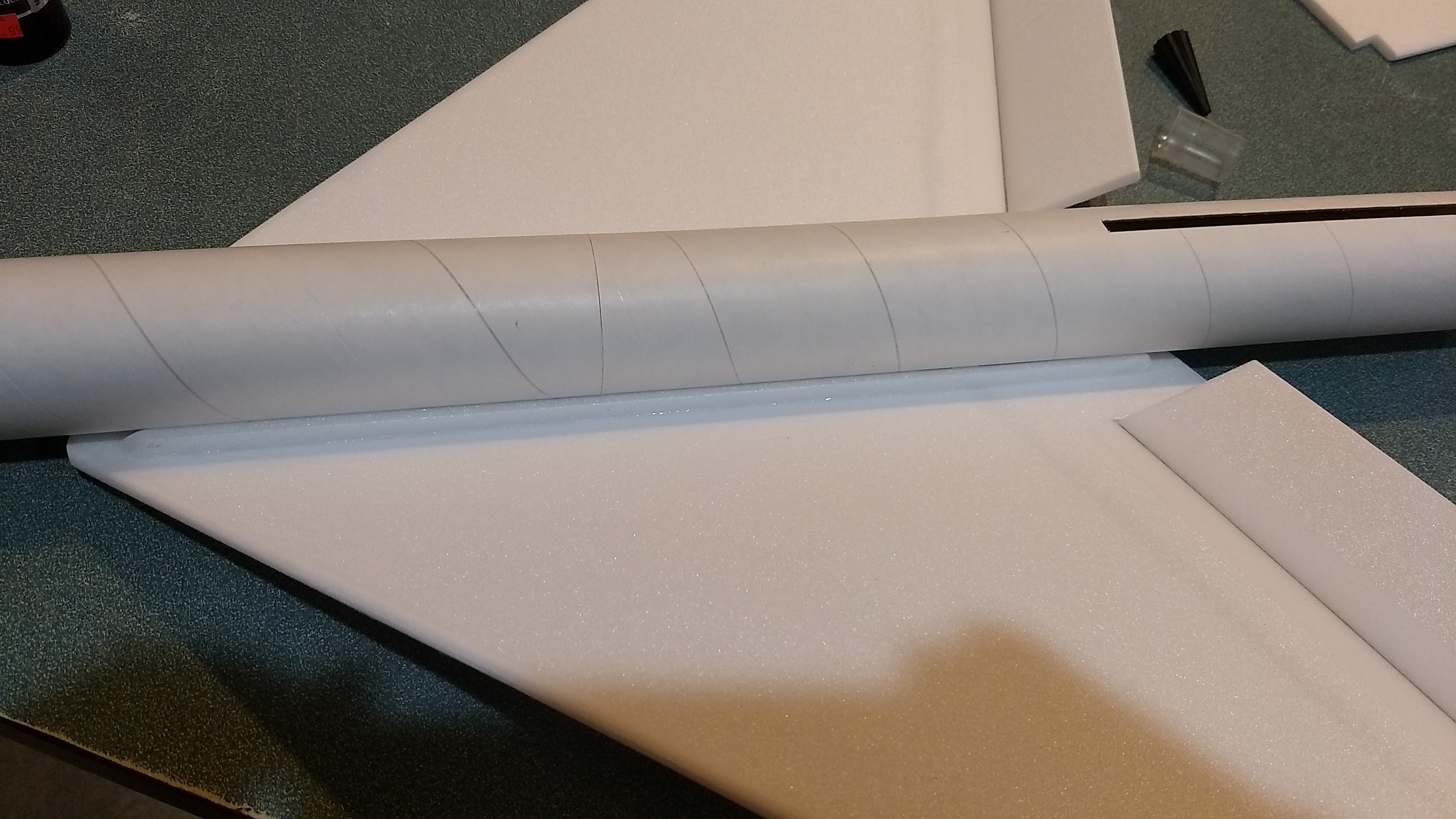
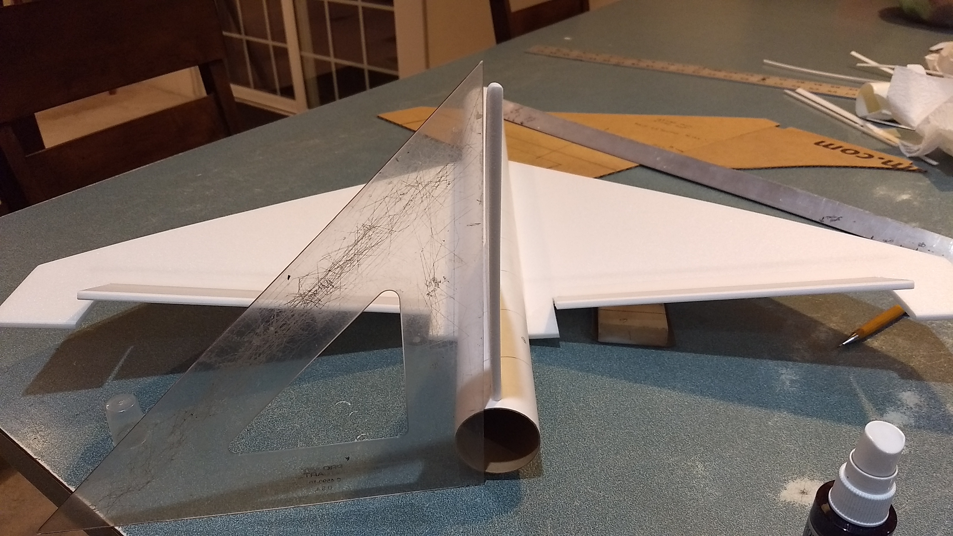
- Lightly sand the body tube on the wing line, then unfold the wing and apply CA+ to the taped joint, about 1/2″ on either side of the joint, and a 1/2″ wide sqiggle of glue on the body tube around the wing line.
- Set the wing onto the body tube upside down so that the wing tips can hang over the edge of a table. You want the table to hit the wing about 2/3 back from the leading edge and it will automatically set the wing angle. Make sure the glue joint has set before you flip the model over. The angle isn’t critical as long as it is approx the same on each side. Your dihedral will be about 2-2.5″ on each wingtip, it isn’t critical as long as both are similar.
- Glue a reinforcing strip onto each side of the wing/tube joint, apply glue to the angled surface and the flat wide surface and gently push it into the joint, this provides extra gluing surface for the wing joint. Don’t push it in too hard. Then apply a fillet of glue to the joints to hold it in place.
- Test fit the vertical stab into the slot. It helps to prop up the wing tips the same amount on each side then use a right angle to make sure the vertical stab is straight. Once the fit is right, glue the vertical fin into place Apply a light filet to both sides of the vertical stab on the inside and outside of the body tube.
- Test fit the motor mount into body tube. Make sure it fits, or sand very carefully. The tube will slide under the vertical stab tab and the three tabs you glued onto the motor tube help center the motor tube. NOTE*** the motor hook is taped at the front, make sure you have the front forward when you glue it in place. Apply glue to the joints where the foam tabs hit the body tube and the vertical stab tab hits the motor tube, make sure the vertical stab stays perpendicular. Inset the motor tube so that it is flush with the vertical stab tab at the rear, about 3/4″.
- Apply CA+ each of the control horns and press them in place in the bottom of each control surface into the pre-made holes. Note the control pushrods go on the inside of each control horn nearest the body tube The holes face forward and the pushrod should be closest to the body tube. Apply a fillet around the control horn and the top of the prongs on the top of the wing.
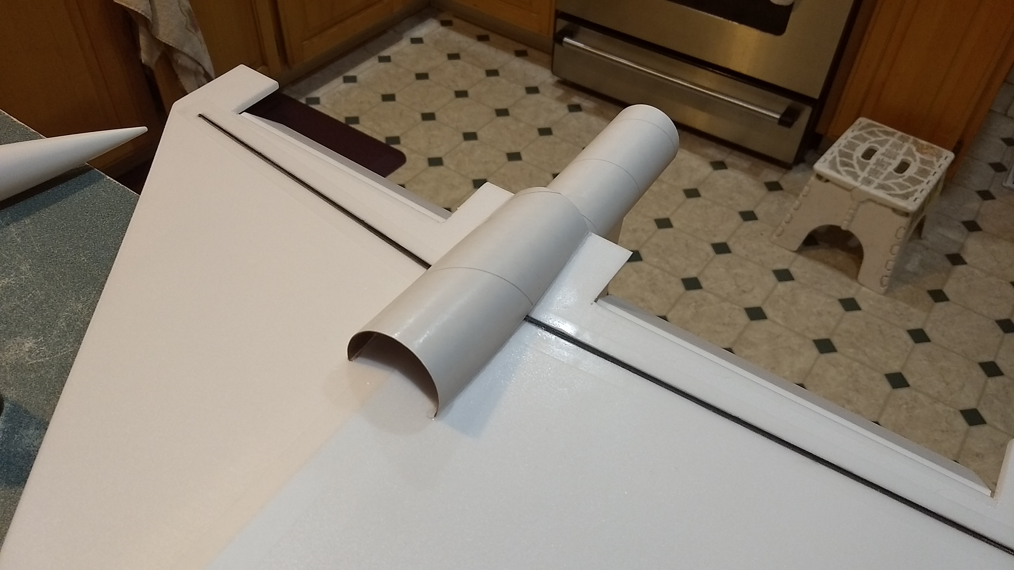
- Glue the intake scoop onto the bottom of the wing with the rear flush with the rear of the wing. If you install this you need to land on grass with a sort of flare and plop method to avoid damage. You may omit the scoop if you want to.
- Glue the foam reinforcing piece into the mouth of the scoop and against the middle of the wing to reinforce it. Sand/cut to fit if needed. This helps protect the scoop shape during landing.
- Glue the canards into the nose cone in the pre-cut slots. The canards go into the cone about 1/4″ and angle upwards a bit. Angle isn’t critical just try to make them match.
- Put some sandpaper over the nose cone and carefully sand the cockpit to match the cone and then glue in place. The rear of the cockpit will be very thin at the back and the front should stick up a bit, see photo for clarity. The stickershock decals also include a cockpit and black piece that goes ahead of the cockpit that you can use instead of the foam cockpit piece if you wish.
The basic construction is now complete.
Radio Installation
Note: Your radio needs to be configured for Delta mixing, this means that the servo arms will move the same direction during elevator stick movement and opposite for aileron stick movement. Connect your servos to the receiver one in the aileron connection and one on the elevator connection and apply power. Use a servo arm at least 9/16” long and with holes small enough that there won’t be slop with the pushrod wire when installed. I use the hole furthest out on the servo arm, to maximize movement. On some servos there are a long two-ended servo arm, you can trim off one end if needed to get sufficient length. Zero out any trim settings on the transmitter. The model once the motor has burned out is nose heavy and flying wings lose pitch authority when nose heavy so you want as much up elevator travel for trim/flare as possible.
- Connect a servo to each pushrod. If the pushrod is too tight, you can use twist an X-Acto knife in the servo arm hole to make it larger, but be careful and do not make it too large. Once connected, tape each servo in place so that the control surfaces are centered. Flip the model right side up and look at it from the rear. Moving the transmitter stick back(up elevator) should move both elevons up. Moving the transmitter stick to the right should move the right elevon up and the left elevon down. If you can’t get the servo reversing to give you the right polarity try swapping aileron/elevator inputs to the receiver or turning the servos over and swapping the servo arms to the other side of the output shaft. If that is correct, continue.
- Flip the model upside down and supported. The servos may be attached to the model using double back servo mounting tape(not included) or by directly gluing the servo to the wing with foam safe CA+. Double back servo tape can loosen over time and with exposure to heat, I prefer to glue the servo in place. With the radio still on, put a moderate amount of glue on the servo, being careful not to get any near the output shaft, and set it in place on the model keeping the control surface centered. Do the same to the other side. Make sure the glue is set before continuing. Note** The servo wire should point toward the front of the model and the servo should be butted next to the body tube. Apply a fillet of glue around the servo/wing to help secure it and let it cure.
- Attach a 12″ servo extension to each servo.You just need to be able to route the wire to the front of the tube to attach it to the receiver.
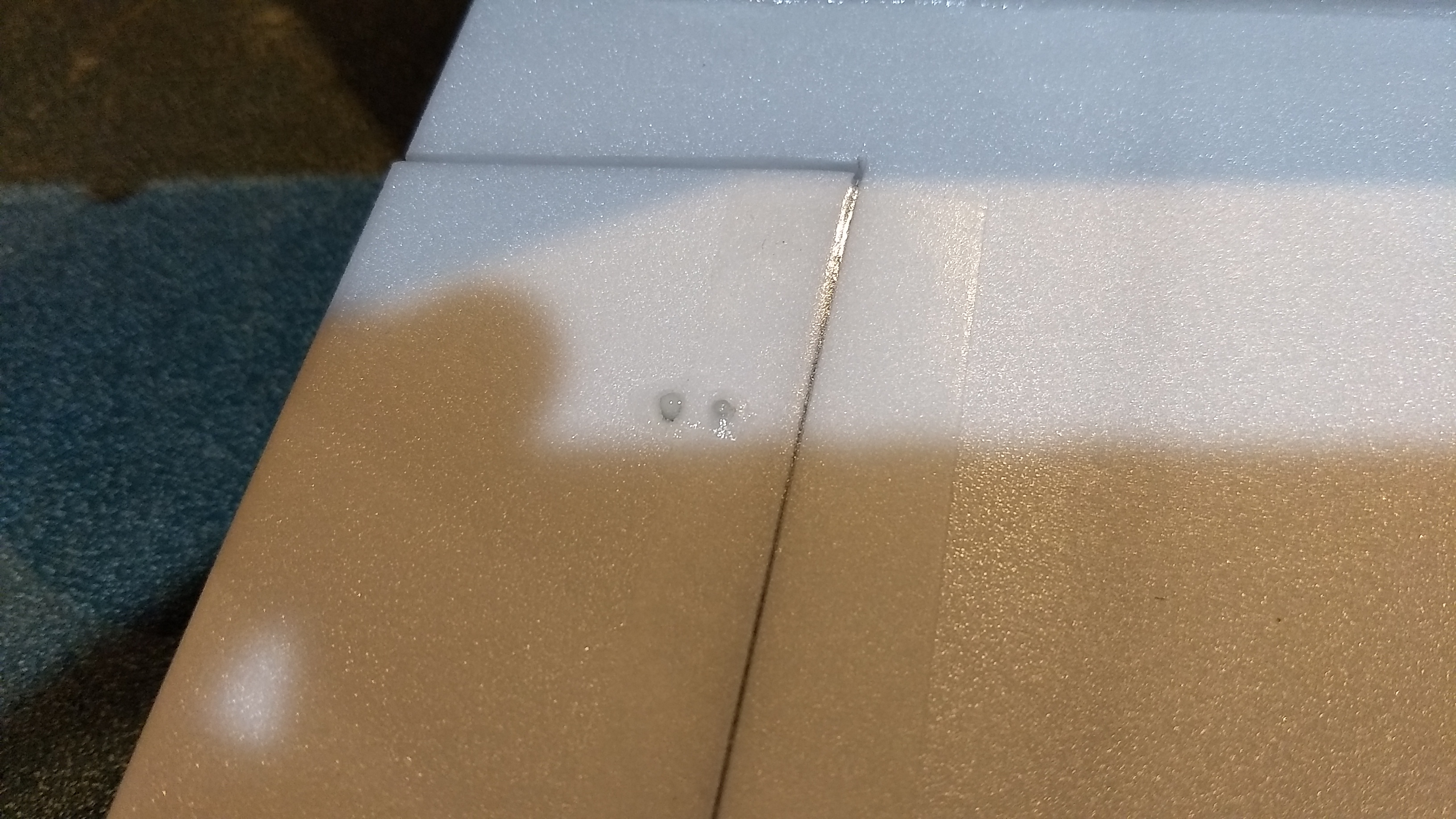
- Make a 1/8″ wide by 1/2″ long slot in the center of the wing and through the body tube and pass the wires through to the inside and toward the front. You can use clear packing tape to hold the servo wiring down onto the wing. See photo for more clarity.
- Attach the servo wires to the receiver and make sure they are going the right direction.
- Flip the model back right side up. Make sure the control surfaces are centered, use trims if needed. Now measure the control surface movement. Full elevator movement should be 7/8” in each direction, aileron movement should be 1/2″ in either direction. Since the model will be nose heavy, extra elevon movement helps to give sufficient authority during glide.
- If you have a flap/elevator mix you can program up elevator to a switch setting. The model needs a very slight amount of down trim for boost and 1/4″ of up trim for glide. If you can’t set the up elevator trim to a switch on your radio you’ll have to manually put in boost and glide trim which is hard to do while flying the model.
- Use the included Velcro to attach the receiver insde the body tube far enough back to clear the nose cone shoulder.
- I attached the battery on the inside bottom of the body tube with velcro making sure the nose cone shoulder clears the battery. I did this to get the correct CG. You can also attach the velcro to the inside bottom shoulder of the nose cone if the balance comes out right.
- Insert your heaviest loaded rocket motor into the motor mount
- Support the model at the balance point indicated for boost. I use two pencils with the eraser pointed up and held in place with a small hand vice. Place the model upside down on the pencil erasers on the balance point indicated above. Use pieces of the included lead weight as far forward into the tip of the nose to balance it, or in the tail as needed. Glue the lead weight in place so it does not shift during flight. Do not try to fly the model too nose or tail heavy. Remember, a nose heavy model flies poorly, a tail heavy model flies once
- I did not paint my model since it is all white. However if you wish to paint it, I can only recommend testors/model master enamel spray at this time, others I’ve tried damage the foam surface. I recommend flat colors as they dry faster and the surface imperfections of foam aren’t as noticable.
- You can use a black fine line sharpie to add panel lines if desired.
- If you use the decals from stickershock, after application use a hot hair dryer, warm the decals and press them down to fully adhere them to the foam and cardboard.
- I used the Q from the stickershock decals as I liked that look better than the JQ. The stickershock decals also include a cockpit and black piece that goes ahead of the cockpit that you can use instead of the foam cockpit piece if you wish. You can trim the cockpit decals to fit the foam cockpit and trim the forward section to fit as well.
- Re-install the receiver and battery
Flying: See the General Instruction link at the top for flying instructions. Be ready on the first few flights to keep the model straight till you have the trims set perfectly for boost and glide.
-
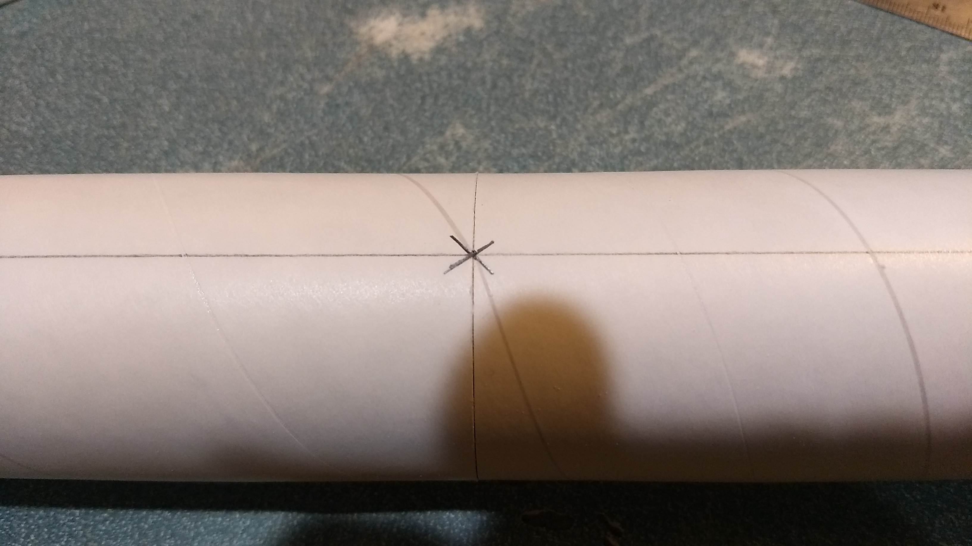
- Join the two tubes so that the line mark is aligned
-
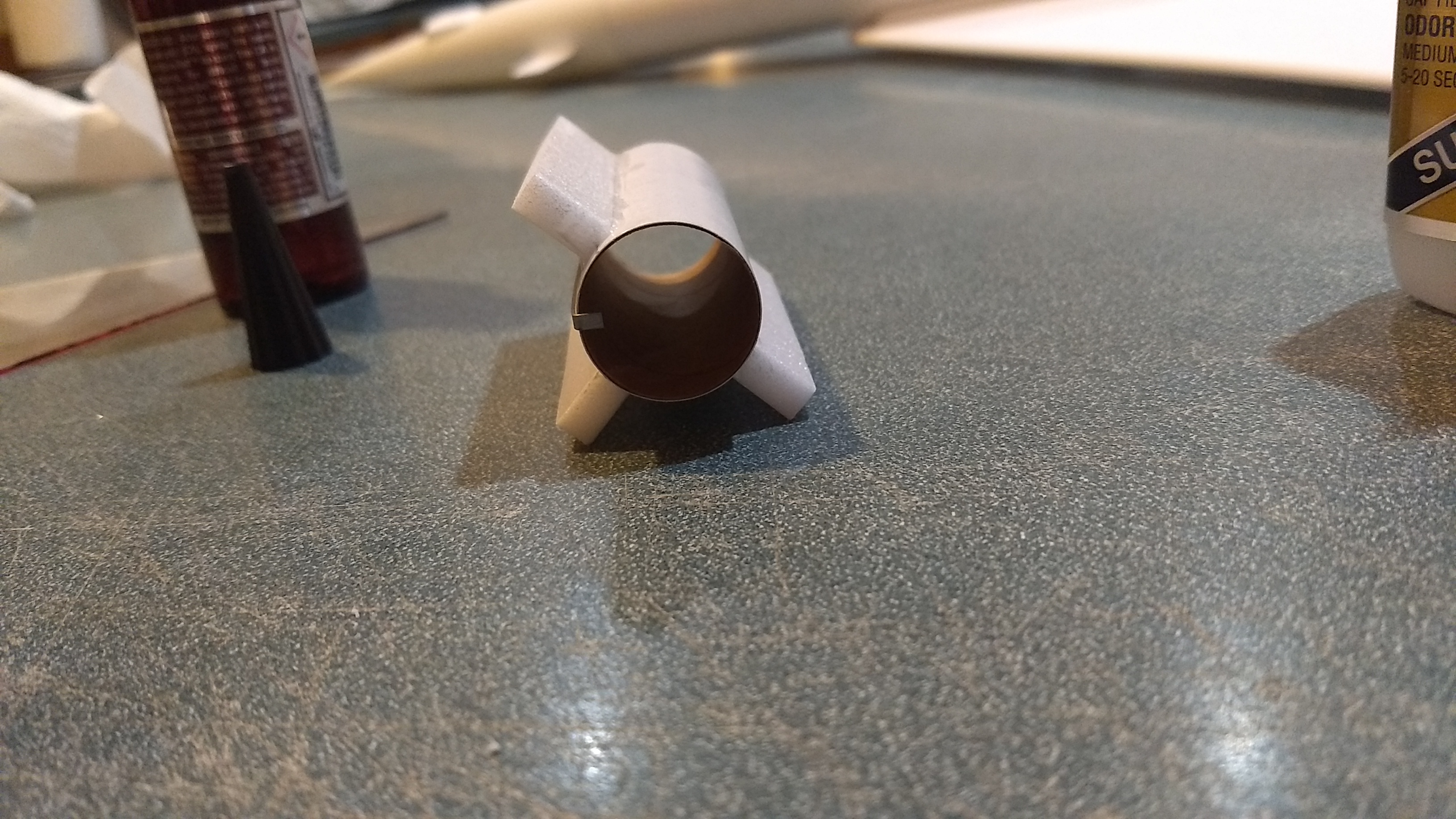
- Add the motor centering strips.
-

- Glue the wing in place
-
- Add the reinforcing strips on each side
-
- Glue in the vertical stab.
-
- Install the belly scoop.
-
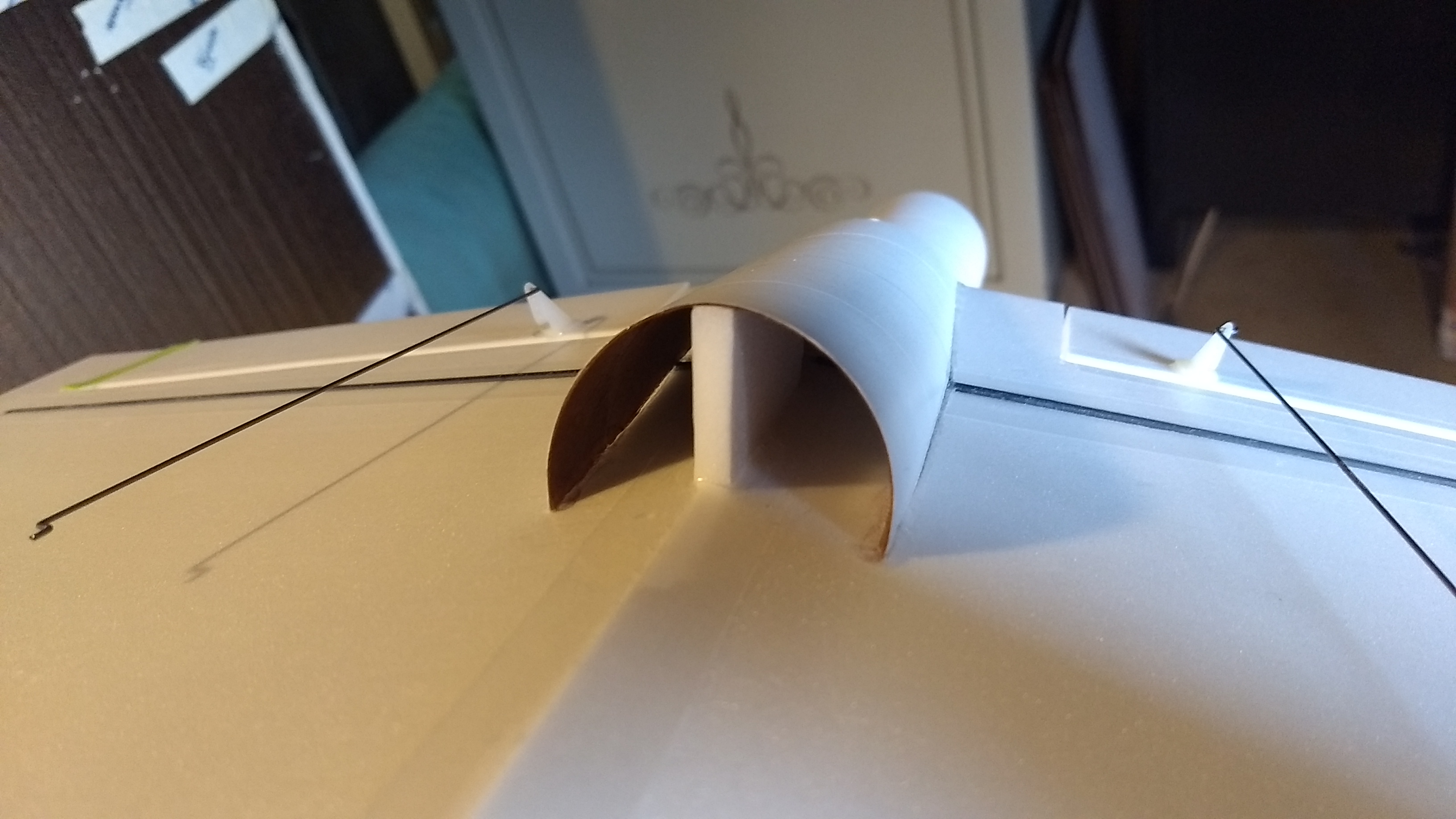
- Intake scoop reinforcing
-
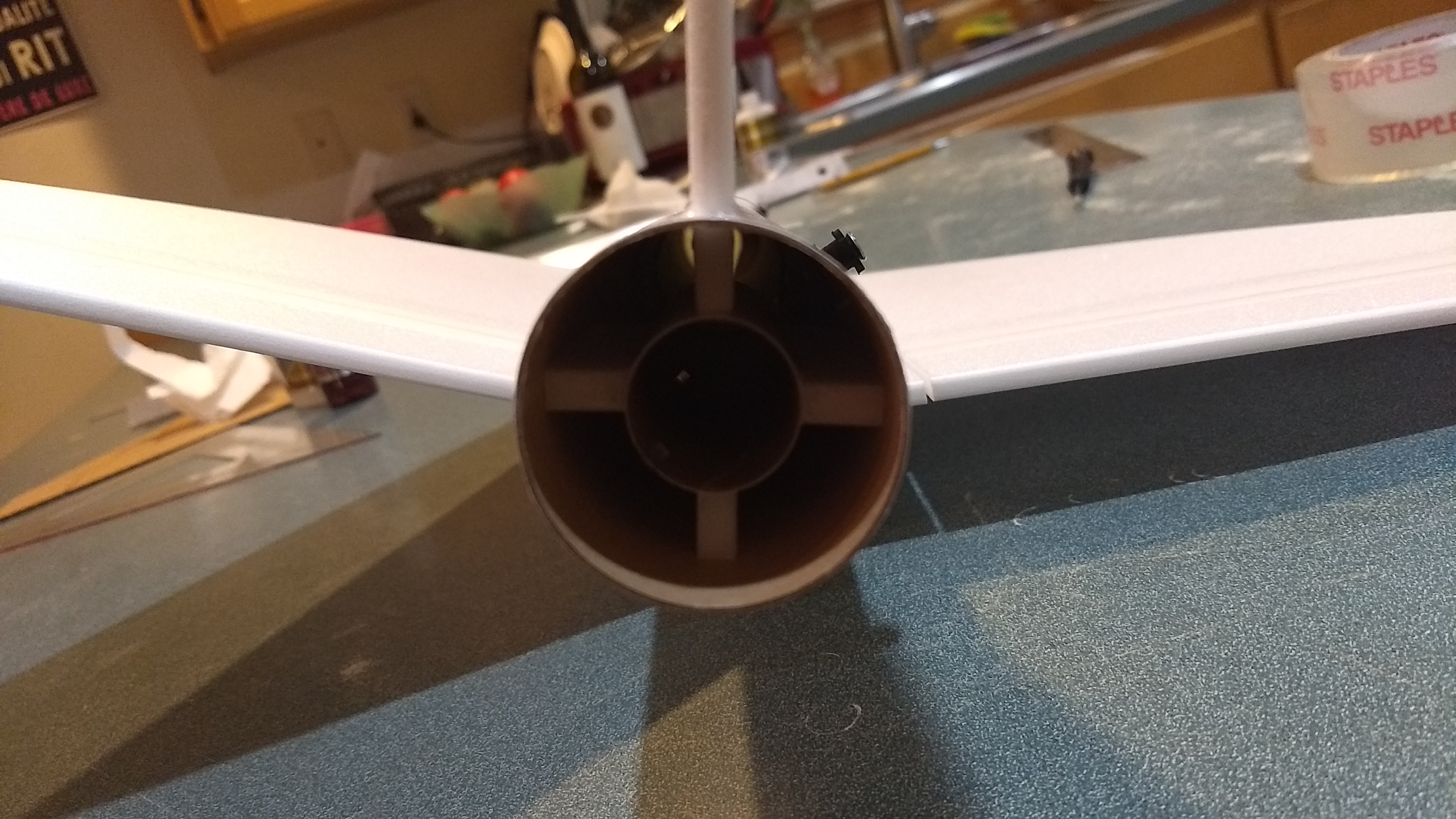
- Glue in the motor tube.
-
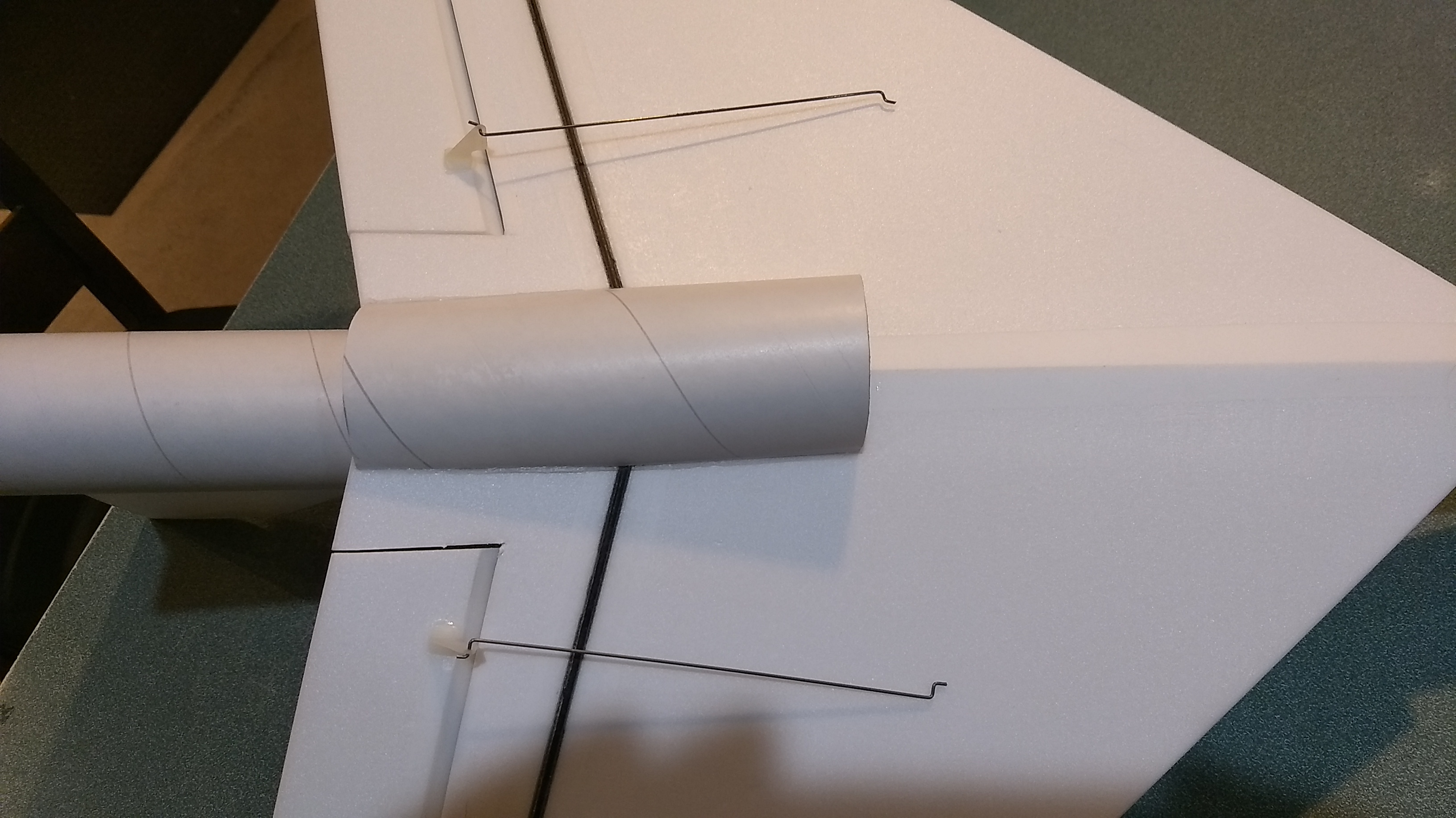
- Install the pushrods/horns
-
- Add glue on the top horn prongs to hold them in place.
-

- Install servos so that control surfaces are level
-
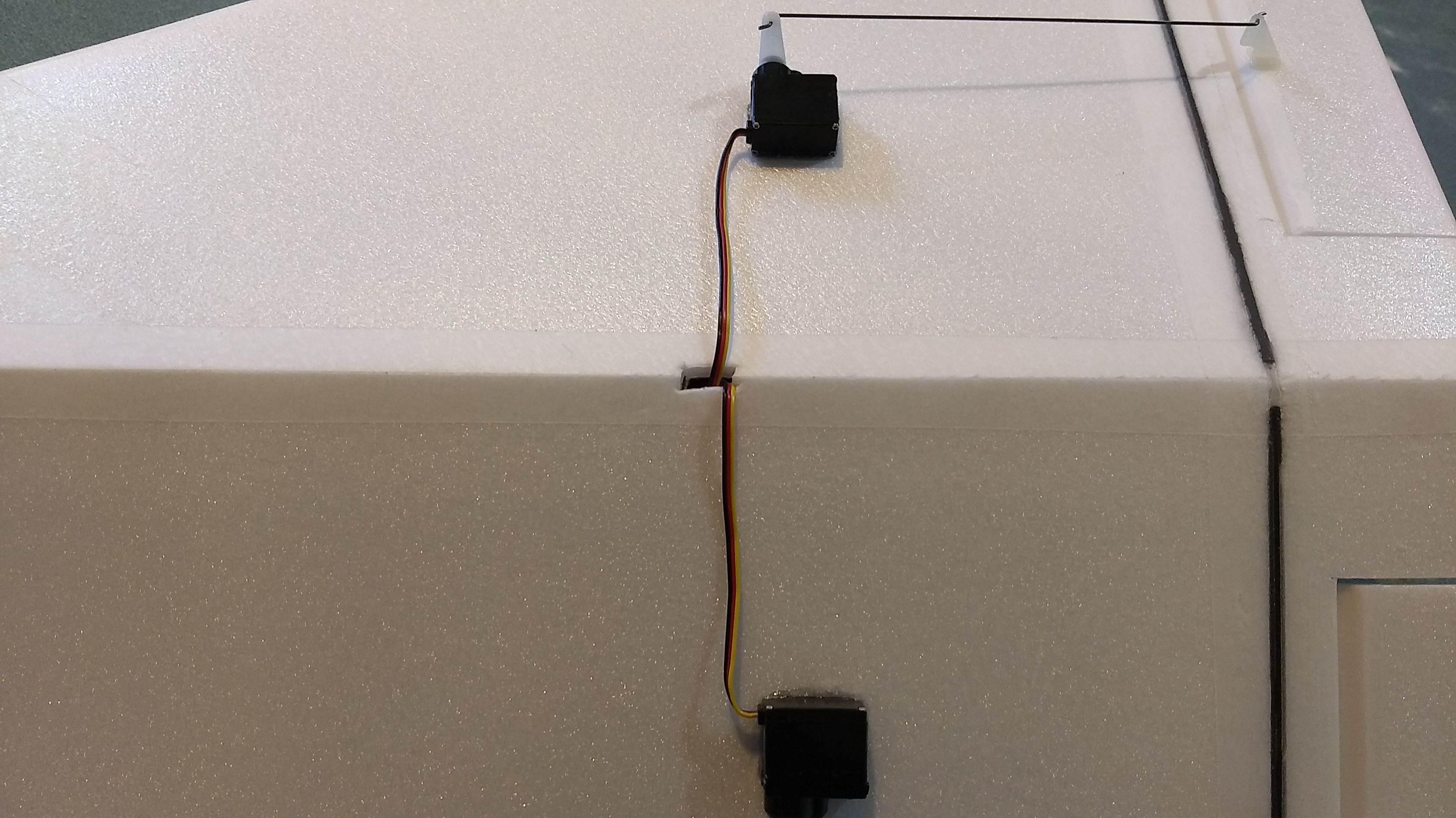
- route the wires into the fuse in the middle
-
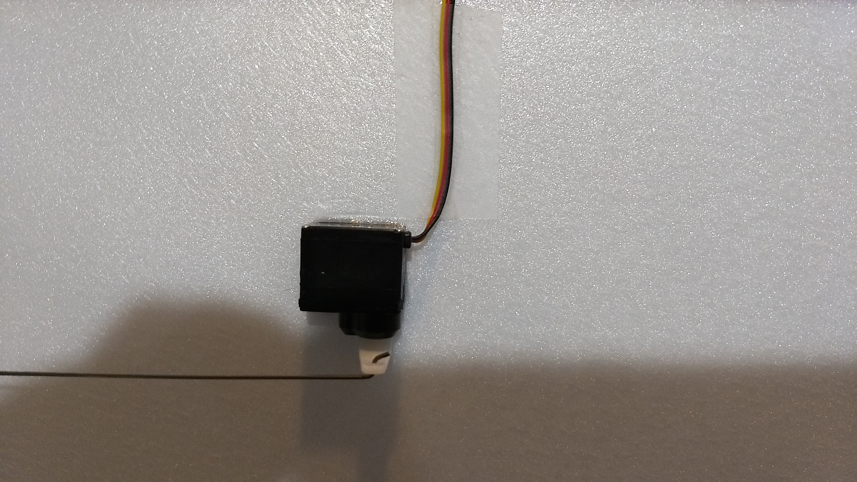
- tape the servo wires down with packing tape
-
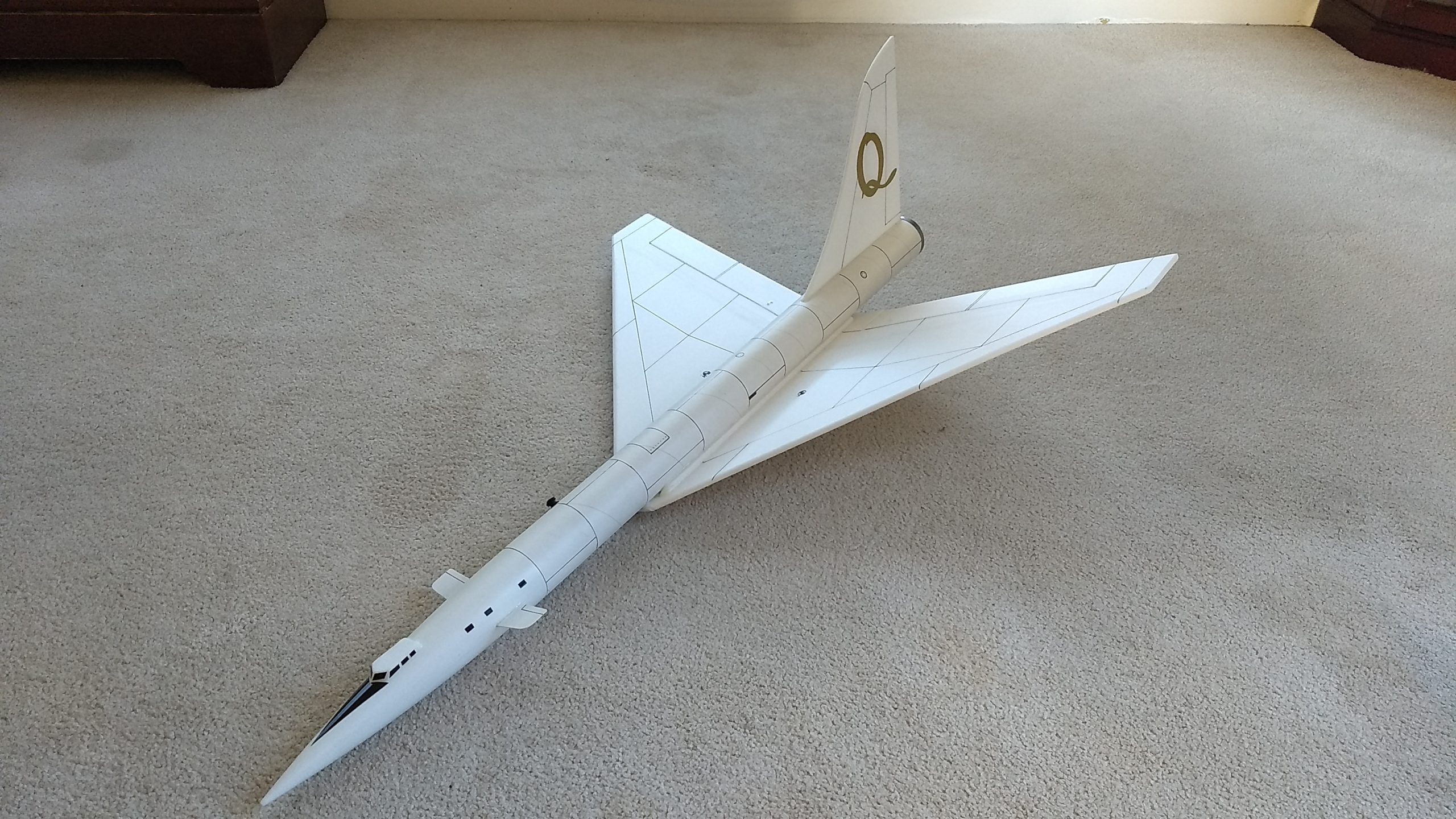
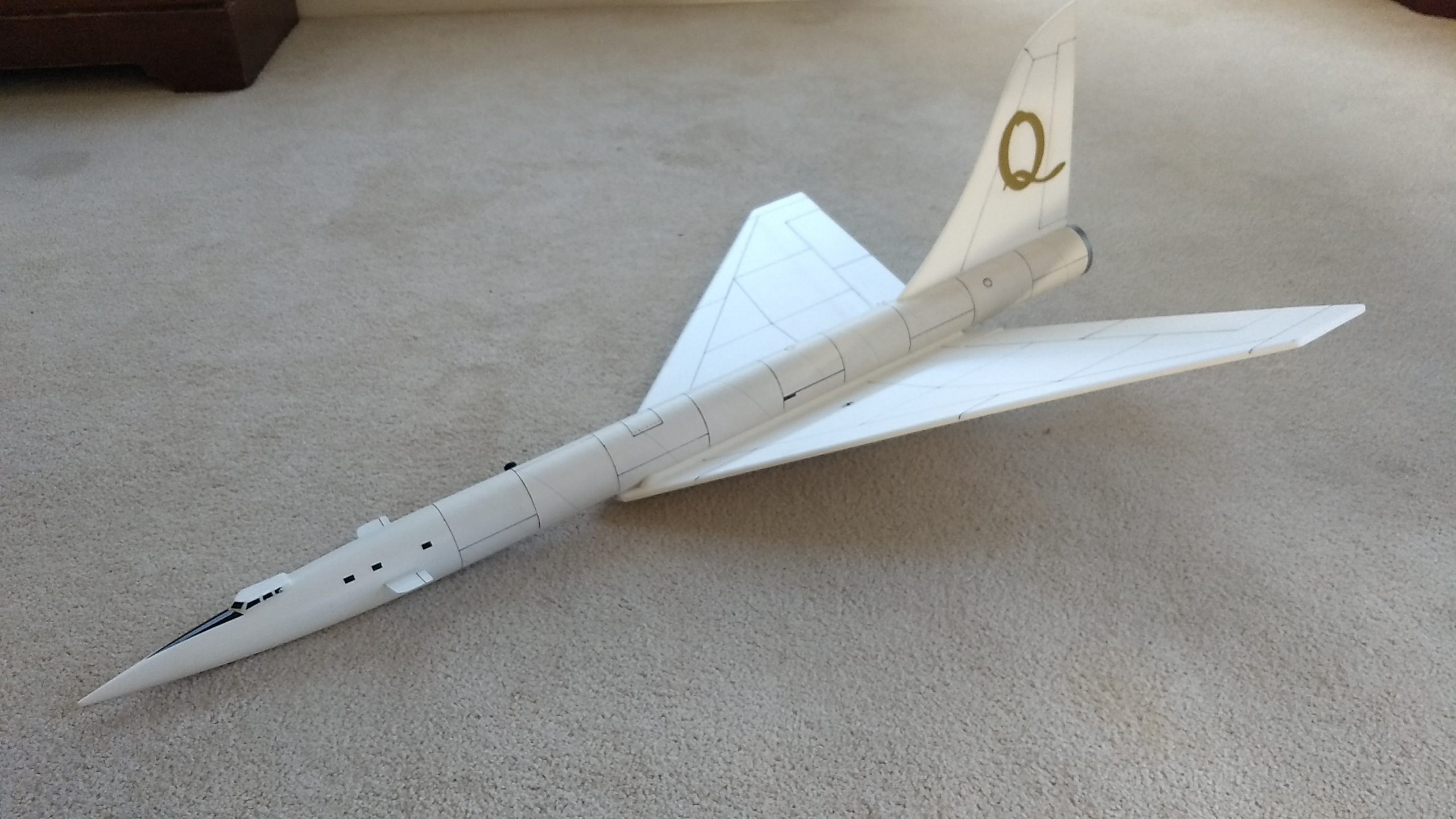
- Completed Model
-
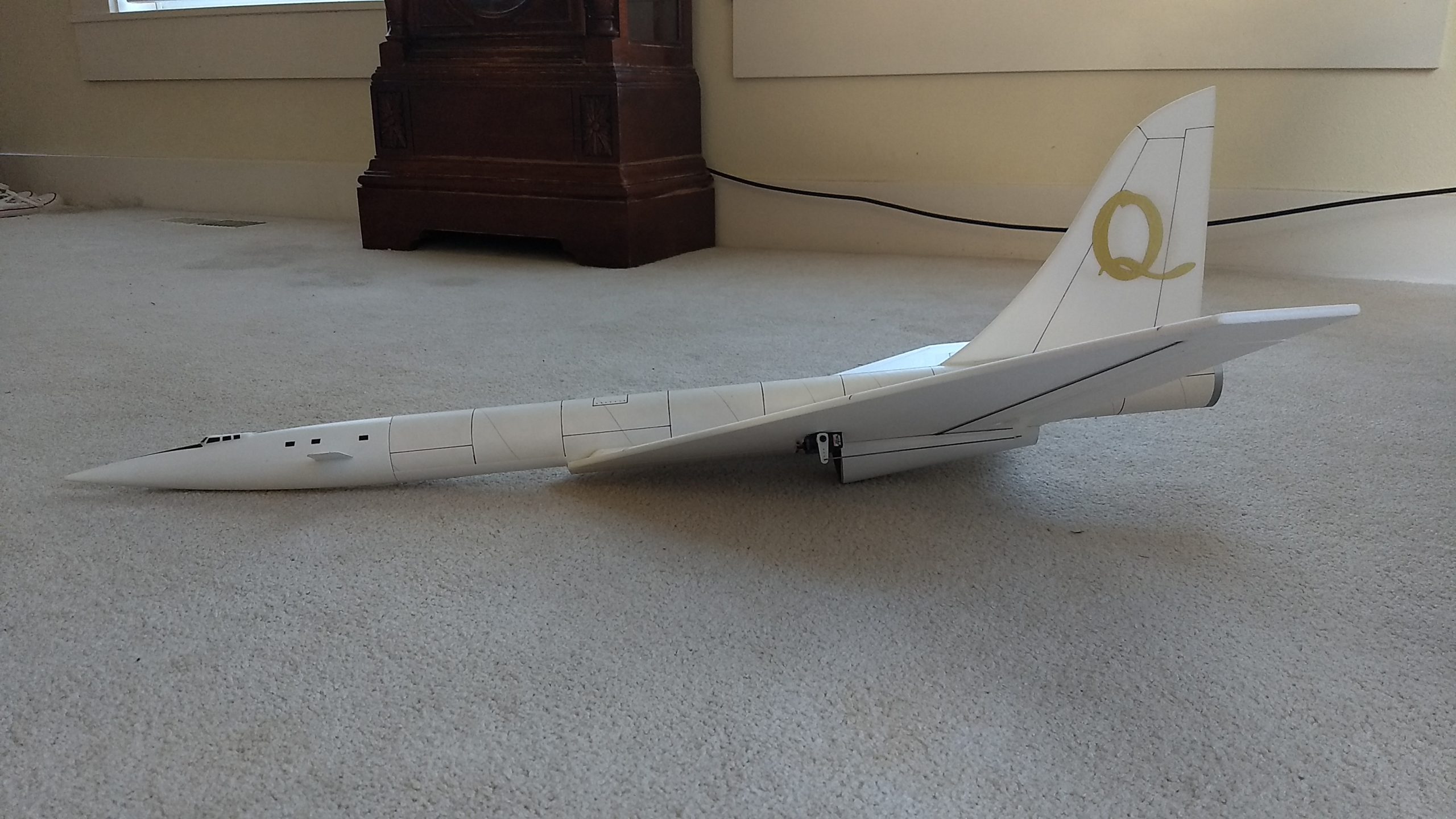
- Side view showing intake scoop
-
- Completed model