The X-20 RC Rocket glider kit is based on the proposed Air Force single man Shuttle concept. Construction is very simple and takes about an hour and a half. The kit includes pre-hinged control surfaces, pre-grooved spar slots and pre-cut 9mm depron parts. Kit includes rail buttons. Length 31″, wingspan 21″, weight 14.5 oz rtf. It uses a profile construction to maximize wing area to give the best possible glide. Please refer to the General information for all kits tab above, then read these instructions completely before starting assembly. Wingspan 21″, Length 31″, Weight 14-14.5 oz rtf.
CG location for rocket flight: 10 1/4” forward of the rear end of the motor tube with battery and motor installed ready to fly.
Unpacking your kit:Carefully slit the tape holding the cardboard sandwich around the foam and gently remove the sandwich from the box, then gently trim the tape holding the top piece onto the bottom piece, should be four pieces of tape. You can then see the foam wrapped in plastic. It’s wrapped pretty well, it will take some time to gently cut with an exacto to remove the plastic wrap, don’t pull on anything or you may crack something, I know it’s a pain but it’s the only way I could make sure they were secure in shipping. There are little foam pieces, don’t lose them, the parts baggie was heavy so is well taped. The spars are taped to one of the cardboard pieces. Kits contain one or two scrap pieces for repairs if you damage anything in construction or flight, just cut and patch in a spare piece of the foam if needed using foam safe CA+.
Welcome to the world of rocket boosted radio control gliders. This is not a model for a novice RC pilot, but anyone who is comfortable with RC flying of a medium speed model should be fine. Read through the instructions, look at the photos and be sure you understand the step before committing to cutting or glue.
Identify all pieces, the kit should contain:
1 wing taped together 9mm
1 Fuselage Side view top 9mm
1 Fuselage Side view bottom 9mm
2 vertical stabilizers 9mm
2 7″ long stabilizer gussets
2 control horns/Pushrods
2 12″ by 3mm carbon spars
2 sets of styrene plates, rail buttons and screws.
1 15″ by 3mm carbon cross spar
2 Motor tube reinforcing strips 2.75″
Motor mount
Velcro(for battery and rx/bec attachment)
Lead weight
Blenderm tape
Notes before starting:
Foam safe CA+(Bob smith super gold + is good) is the only glue recommended for construction. You will also need foam safe accellerator to set the glue. Epoxy is only used for securing the lead weights to the model at the front where weight is needed.
The 9mm depron is a bit harder to sand and can tear easier with a sanding block, I’ve found it’s better to use a straight edge and sharp exacto to do a 1/8″ to 3/16″ bevel cut on the edges of the wing/stabilizers instead of trying to sand them round. For the few steps that require sanding below use a hard sanding block and 320 grit paper and go light and take your time.
Assembly:
- Unfold the wing and use foam safe CA+ to glue the two taped joints, use accelerator to set the glue.
- At this time I would bevel the leading edges and trailing edges of the wing and elevons, I just beveled the top edge about half way and left the bottom edge alone. Don’t bevel the wing tips where the vertical stabs will go, those edges need to stay square.
- Lightly bevel the fuselage top view just to break the edge slightly. Just bevel the top edge, not the edge with tabs.
- Make a left and right vertical stabilizer, bevel only the outside leading, trailing and bottom edges, the inner edges need to be as cut.
- Flip the wing over so the spar slots are visible. Glue in the 15″ cross spar in the rear slot and glue the two 12″ side spars in their pre-cut slots using foam safe CA+. Once glued apply included blenderm tape over the spars.
- Flip the wing over right side up.
- Glue the motor tube along the fuselage center line so that the rear is even with the rear of the wing. Make sure the taped portion of the motor hook is forward and the hook is offset about 45 degrees from the top of the tube, see picture for clarity. Make sure it is centered and straight then glue in place.
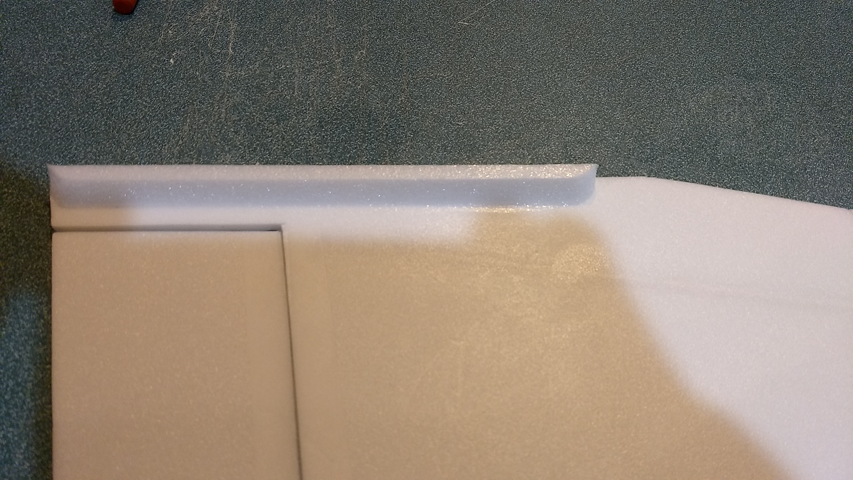
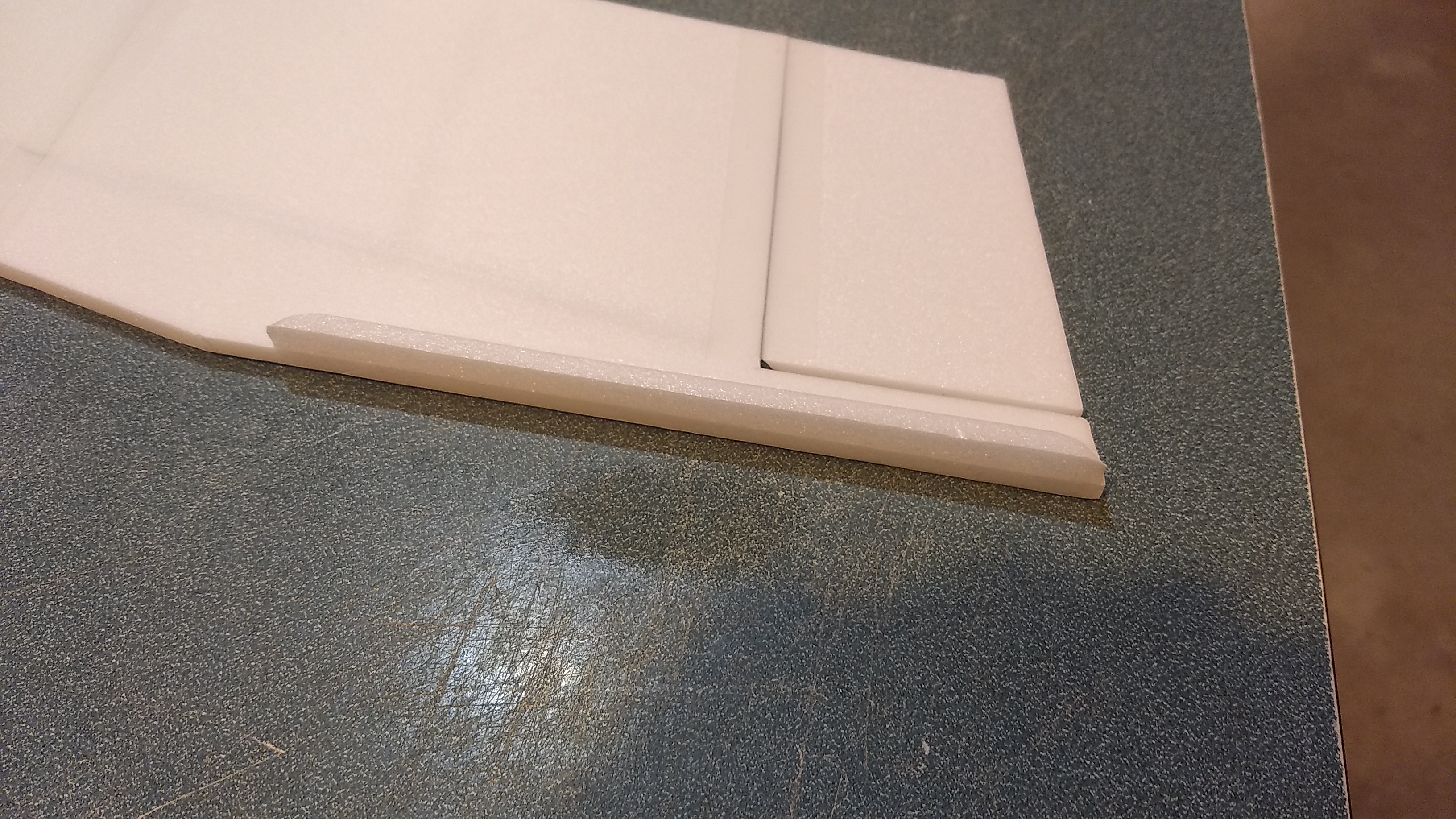
- Glue the two short 2.75″ long foam pieces on either side of the motor tube to reinforce the tube mounting. The angled cut will slide under the motor tube and the rear will be flush with the rear of the motor tube/wing. These may have a rounded front or bevels on both ends just to make them cosmetically a bit nicer looking. They may not look exactly like the photo but do the same job.
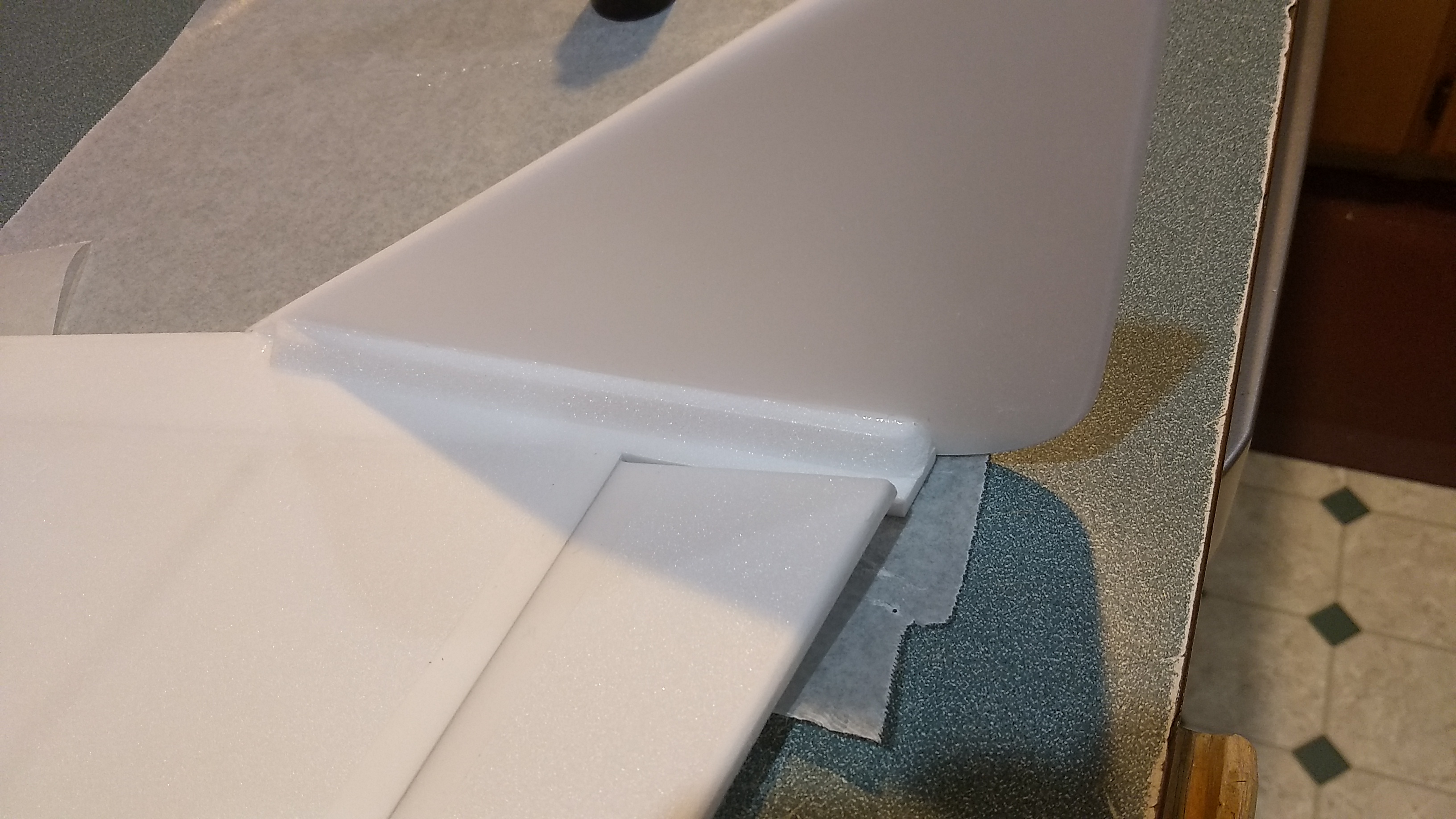
- Put some wax paper under the wing tips. Then glue a 7″ angle cut foam strip along the straight wing tip. The angle cut will be toward the fuselage side and make a gusset to reinforce the wing tip. The gusset will be even with the rear of the wing and not go all the way to the front. Make sure the glue is set. Lightly sand the wing tip to make sure it is nice and square.
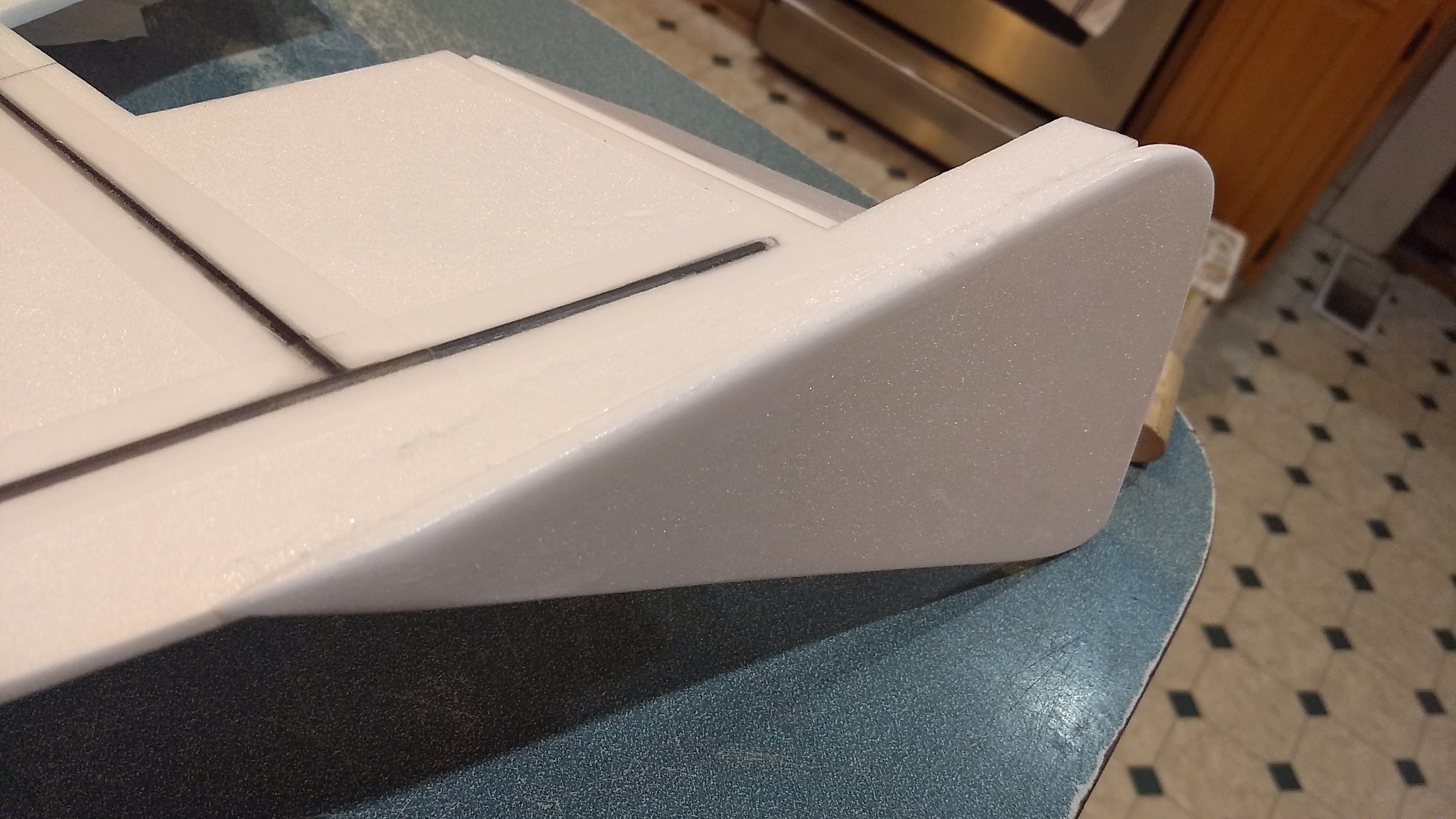
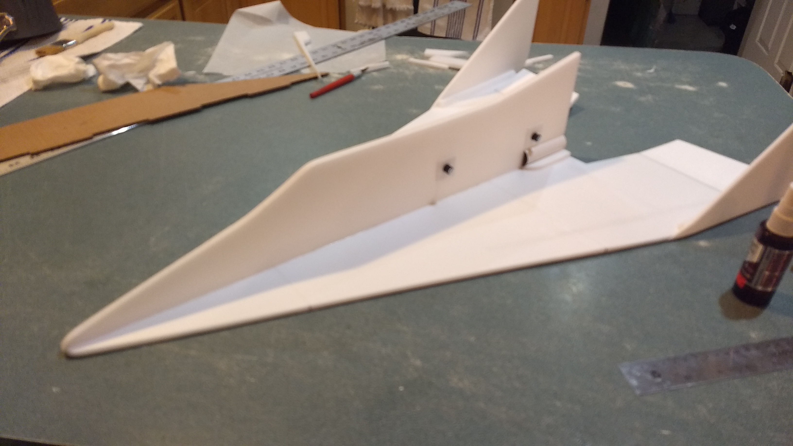
- Put some wax paper under each wingtip then glue each vertical stab onto each wing tip, the pointy front of the stab will be flush with the front of the wing tip, the rear rounded portion will stick back past the elevon about an inch and a half.
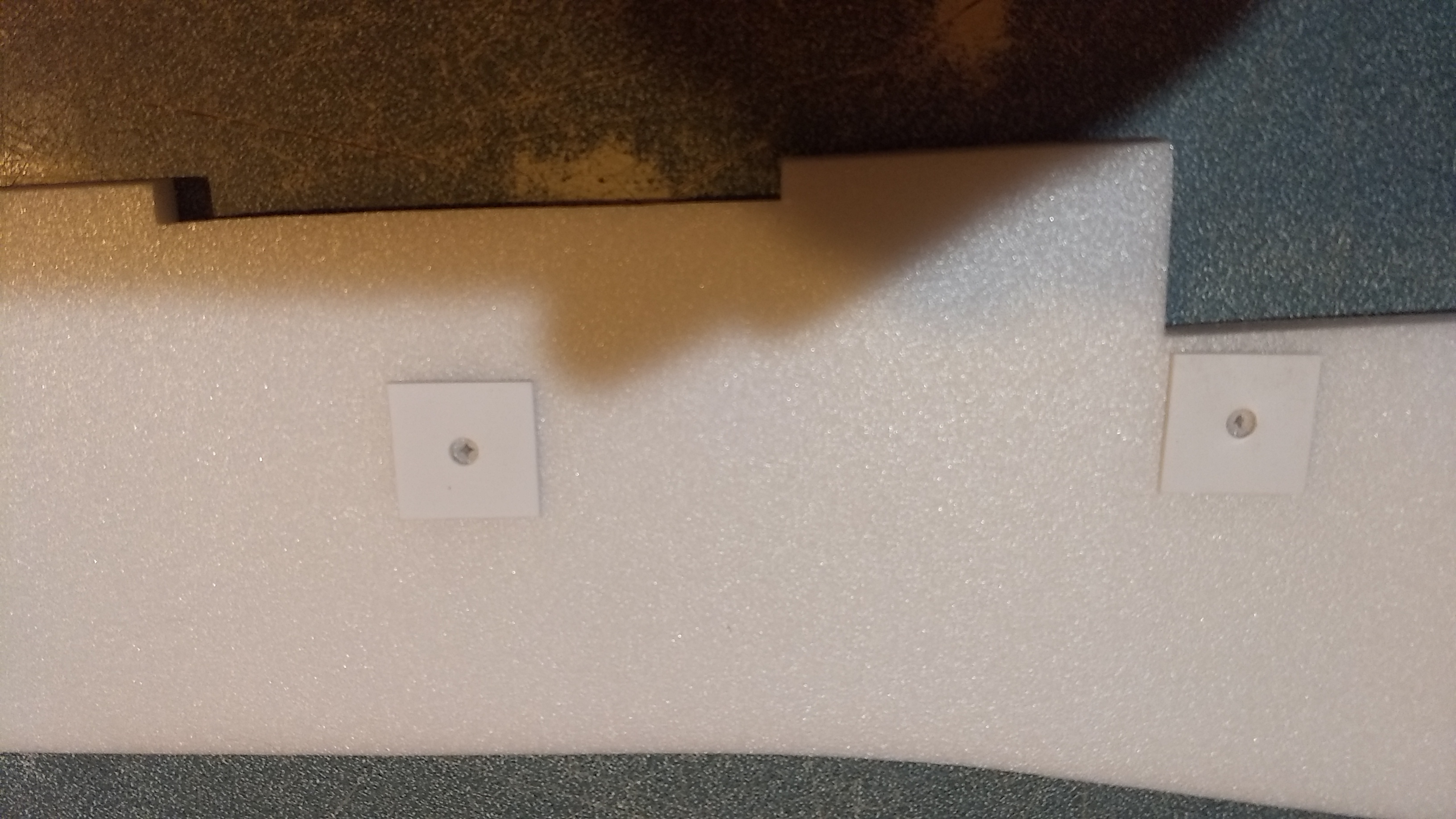
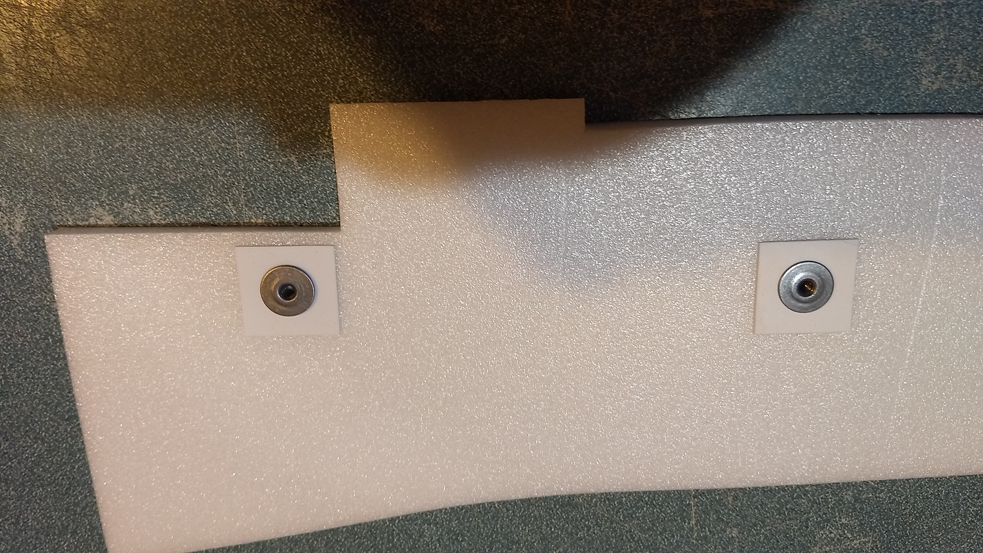
- Glue a square styrene reinforcing plate onto the fuselage side centered on each of the two pre-made holes. These support the rail buttons. Repeat on the other side.
- Insert a T-nut from one side into each of the plastic styrene pieces, then install the rail button and screw onto the other side. These are located so that the rail should not interfere with anything on the model.
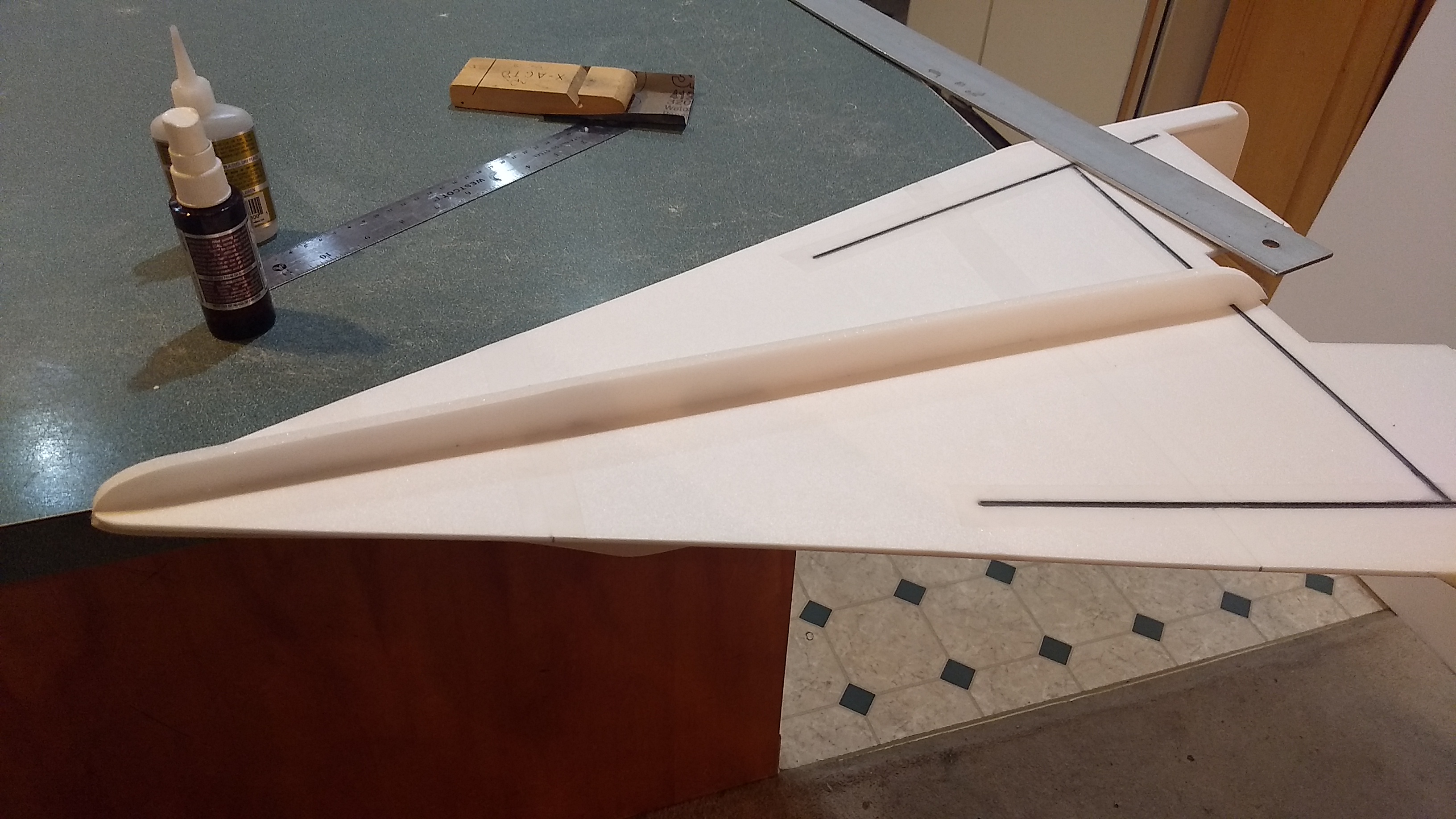
- Test fit the upper fuselage into the slots in the wing, then glue it in place making sure the wing stays flat and the rear is straight along the motor tube. Sometimes the foam has some warp to it, the slots should keep it straight but make sure the front and rear that are not slotted stay straight as the glue sets.
- Flip the model over and glue the bottom foam skid in place. The blunt rounded end is flush with the rear of the model and the tapered end is even with the front. This piece simply provides some standoff to protect the receiver/battery and servo arms if you land on a firm surface or rough terrain. If the mounting surface is not quite square you can sand lightly, but it really doesn’t matter if it is perfectly square to the wing, it’s just a standoff, my prototype I assembled was quite off and I did not notice but it made no difference.
- Sand the nose to a pleasing round shape.
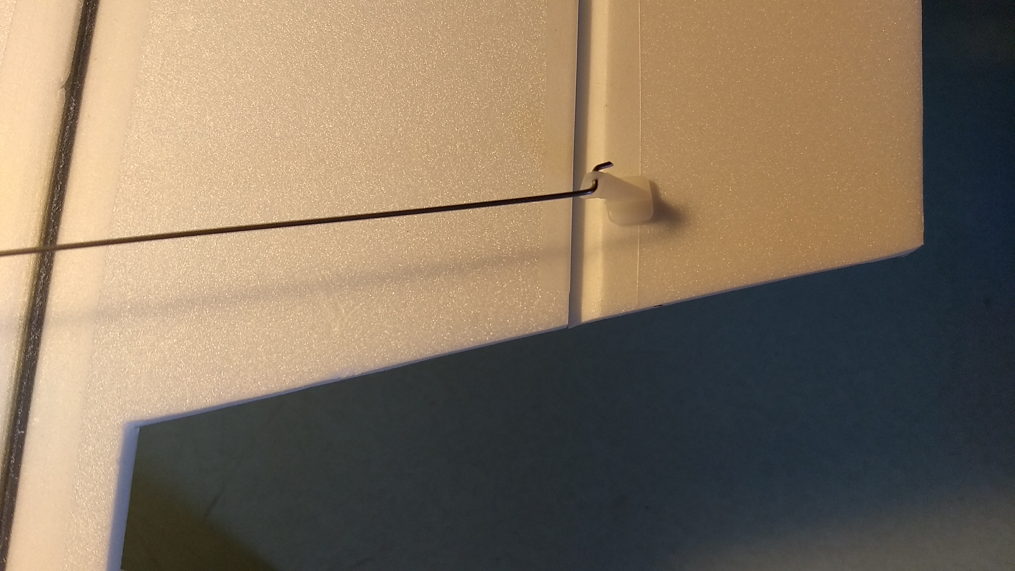
- Glue a pushrod/control horn into each pre-made set of holes in the bottom inboard edge of each elevon. I mount them so that the pushrod is closest to the fuselage side so that the pushrod angles in slighty at a natural angle so the servo is closer to the fuselage.
The basic construction is now complete.
Radio Installation
Note: Your radio needs to be configured for Delta mixing, this means that the servo arms will move the same direction during elevator stick movement and opposite for aileron stick movement. Connect your servos to the receiver one in the aileron connection and one on the elevator connection and apply power. Use a servo arm at least 9/16” long and with holes small enough that there won’t be slop with the pushrod wire when installed. I use the hole furthest out on the servo arm, to maximize movement. On some servos there are a long two-ended servo arm, you can trim off one end and use that arm to get sufficient length. Zero out any trim settings on the transmitter.
- Flip the model upside down. Connect each servo to a pushrod. If the pushrod is too tight, you can use twist an X-Acto knife in the servo arm hole to make it larger, but be careful and do not make it too large. Each servo should be on the bottom of the wing, with the servo electrical wire pointing forward and the servo arm pointing toward the wing tip. Tape each servo in place so that the control surfaces are centered With the model right side up look at it from the rear. Moving the transmitter stick back(up elevator) should move both elevons up. Moving the transmitter stick to the right should move the right elevon up and the left elevon down. If you can’t get the servo reversing to give you the right polarity try swapping aileron/elevator inputs to the receiver or turning the servos over and swapping the servo arms to the other side of the output shaft. If that is correct, continue.
- The servos may be attached to the model using double back servo mounting tape(not included) or by directly gluing the servo to the wing with foam safe CA+. Double back servo tape can loosen over time and with exposure to heat, I prefer to glue the servo in place. With the radio still on, put a moderate amount of glue on the servo, being careful not to get any near the output shaft, and set it in place on the wing keeping the control surface centered. Do the same to the other side. Make sure the glue is set before continuing. Note** The servo wire should point toward the front of the model. Apply a fillet of glue around the servo/wing to help secure it and let it cure being careful not to get any glue near the output shaft of the servo. Make sure you don’t try to glue the servo to any taped areas as it won’t stick.
- Re-Attach the servo wires to the receiver and make sure they are going the right direction.
- Make sure the control surfaces are centered, use trims if needed. Now measure the control surface movement. Full elevator and aileron movement should be 5/8-3/4″ in each direction. When setting the control surfaces for neutral use the middle of the wing as your guide for what is level.
- If you have a flap/elevator mix you can program up elevator trim for boost and glide. If you can’t set the up elevator trim to a switch on your radio you’ll have to manually put in boost and glide trim using the trim tabs which is hard to do while flying the model. My model needed about 1/16″ of up trim for vertical boost and approximately 3/16-1/4″ of up trim for glide.
- Mount the receiver to the bottom of the wing as far forward as the servo wires will allow I cut a slot in the keel to pass the receiver through so the keel held the receiver in place crossways. I had to pass one set of servo wires through the slot to connect to the receiver. Tape the servo wires down to the wing to hold them in place.
- Attach the battery to the bottom of the wing using velcro as far forward as the JST adapter wire will allow.
- Insert your heaviest loaded rocket motor into the motor mount
- Support the model upside down at the balance point indicated for boost. Glue pieces of the included lead shot against the keel as far forward as possible as needed to balance it. Do not try to fly the model too nose or tail heavy. Remember, a nose heavy model flies poorly, a tail heavy model flies once. I put the shot into a baggie, then taped it to the front of the model and removed a little at a time till it balanced. I then weighed this amount on a scale. I then took a piece of wax paper, added sufficient epoxy to be able to mix the shot, and put the wax paper on a scale and added shot back to the epoxy till it weighed the same amount(the epoxy adds weight). I then applied it to the bottom of the model against both sides of the keel. Once set, re-check your balance and add as needed. I took this time to put a bit of epoxy on the bottom of the keel at the nose as well to help it hold up on landings. The epoxy/shot may look yucky but once you paint it flat black you won’t even see it. My model needed around 4 ounces of nose weight but this will depend on your components and how much glue you use to mount it. If you are going to paint your model, this will add about 1/2 ounce to the weight and mostly in the rear. I added about 10 grams more lead weight to the nose to compensate for the paint weight. Make sure you re-check the cg after painting.
- I can only recommend testors/model master enamel spray at this time, others I’ve tried damage the foam surface. I recommend Model master flat black. Remove the battery and receiver and tape over the servo connectors so you won’t get paint in them before painting. You should mask over the rail buttons as well.
- You can use a silver fine line sharpie to add panel lines if desired.
- Re-install the receiver and battery, and re-check the balance point again to be sure the paint didn’t shift the CG.
Flying: See the General Instruction link at the top for flying instructions. Be ready on the first few flights to keep the model straight till you have the trims set perfectly for boost and glide.
-
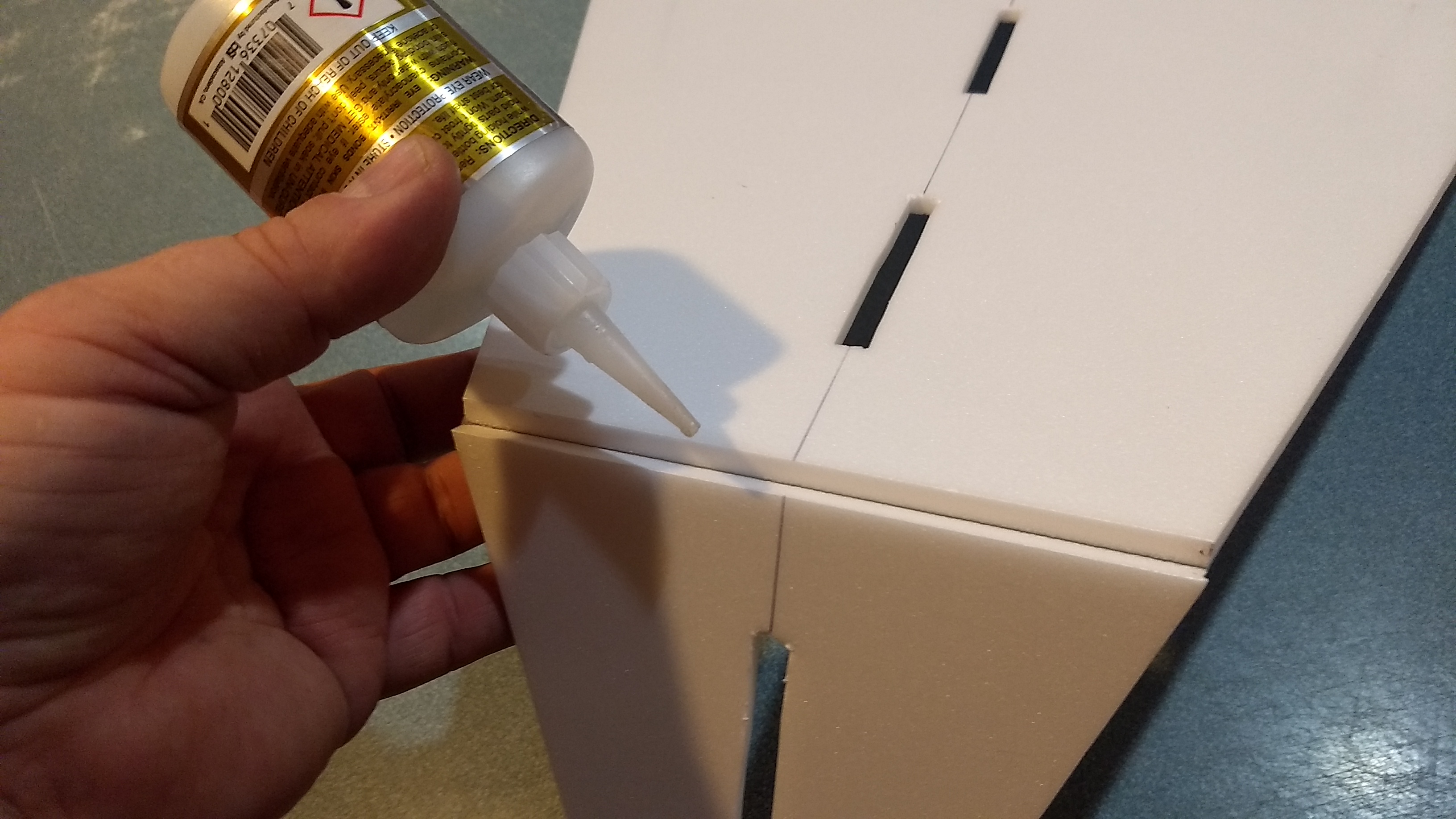
- Glue front tape joint
-
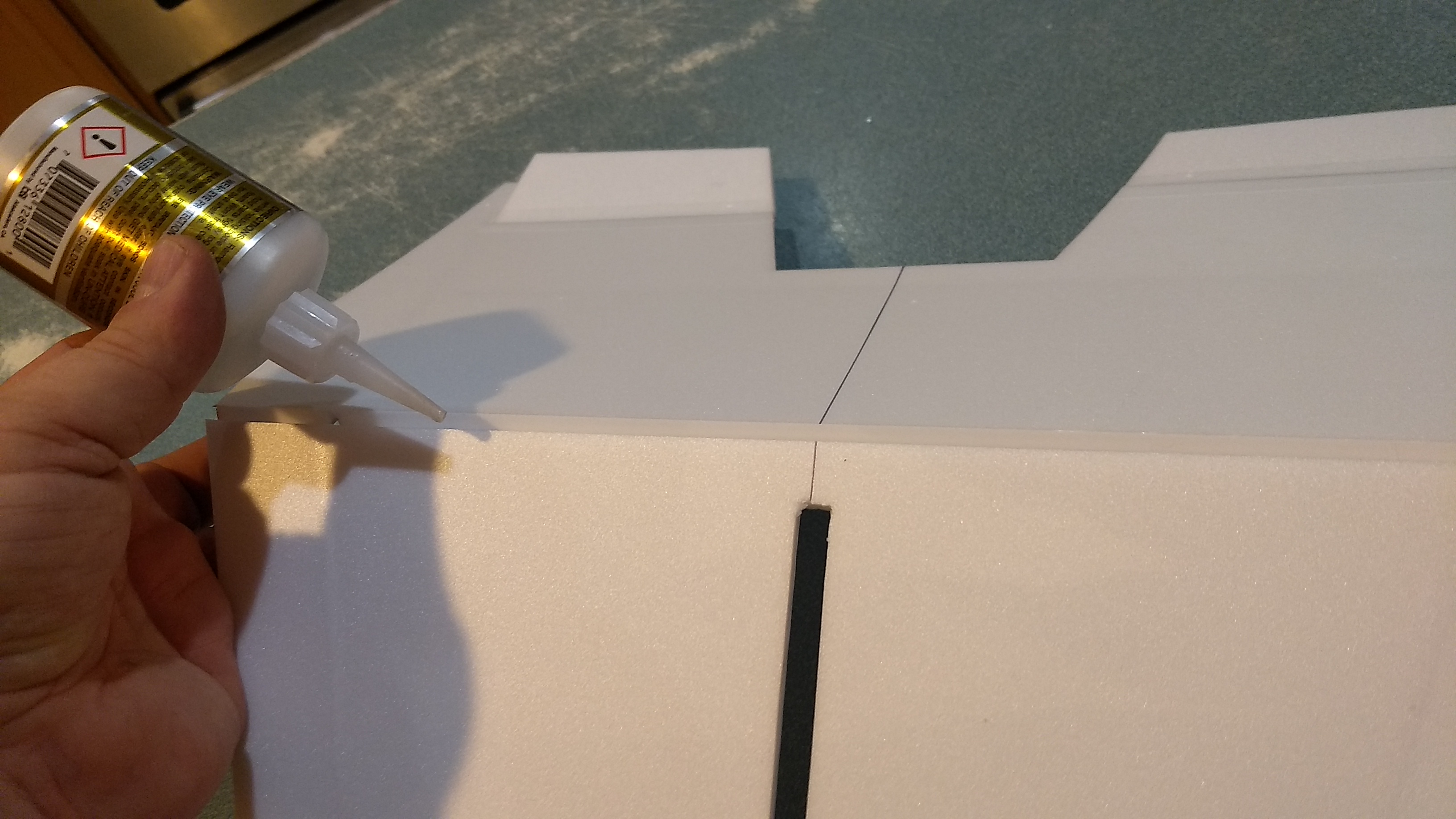
- Glue rear tape joint
-
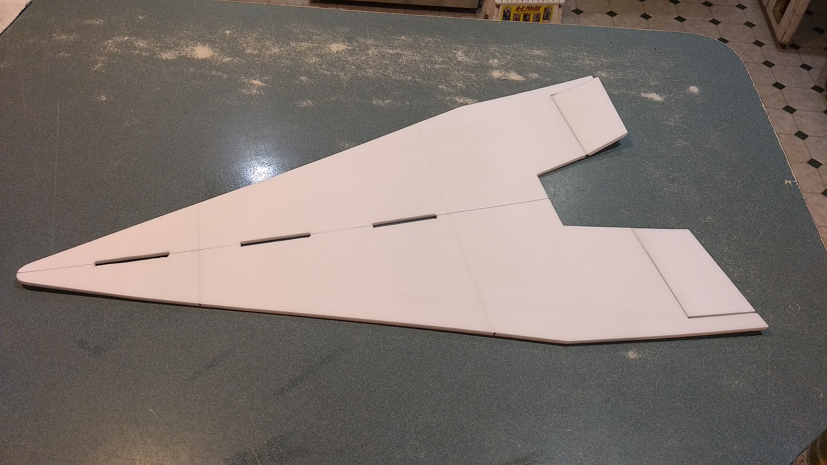
- Make sure Wing lays flat as joints set.
-

- Flip wing over and glue in the 13″ spar in the cross position and the two 12″ spars on each side.
-
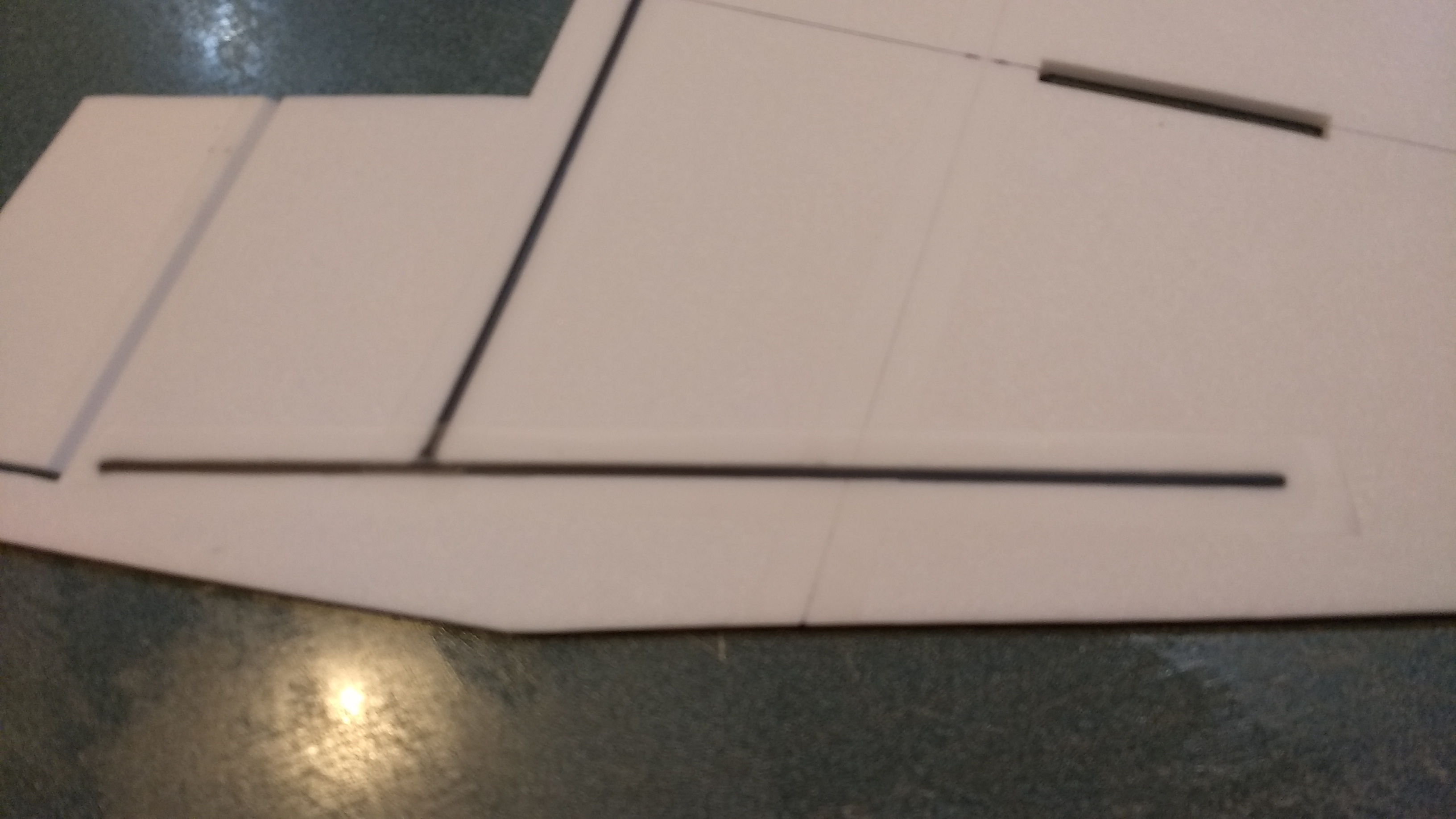
- Tape over all three spars with blenderm tape.
-
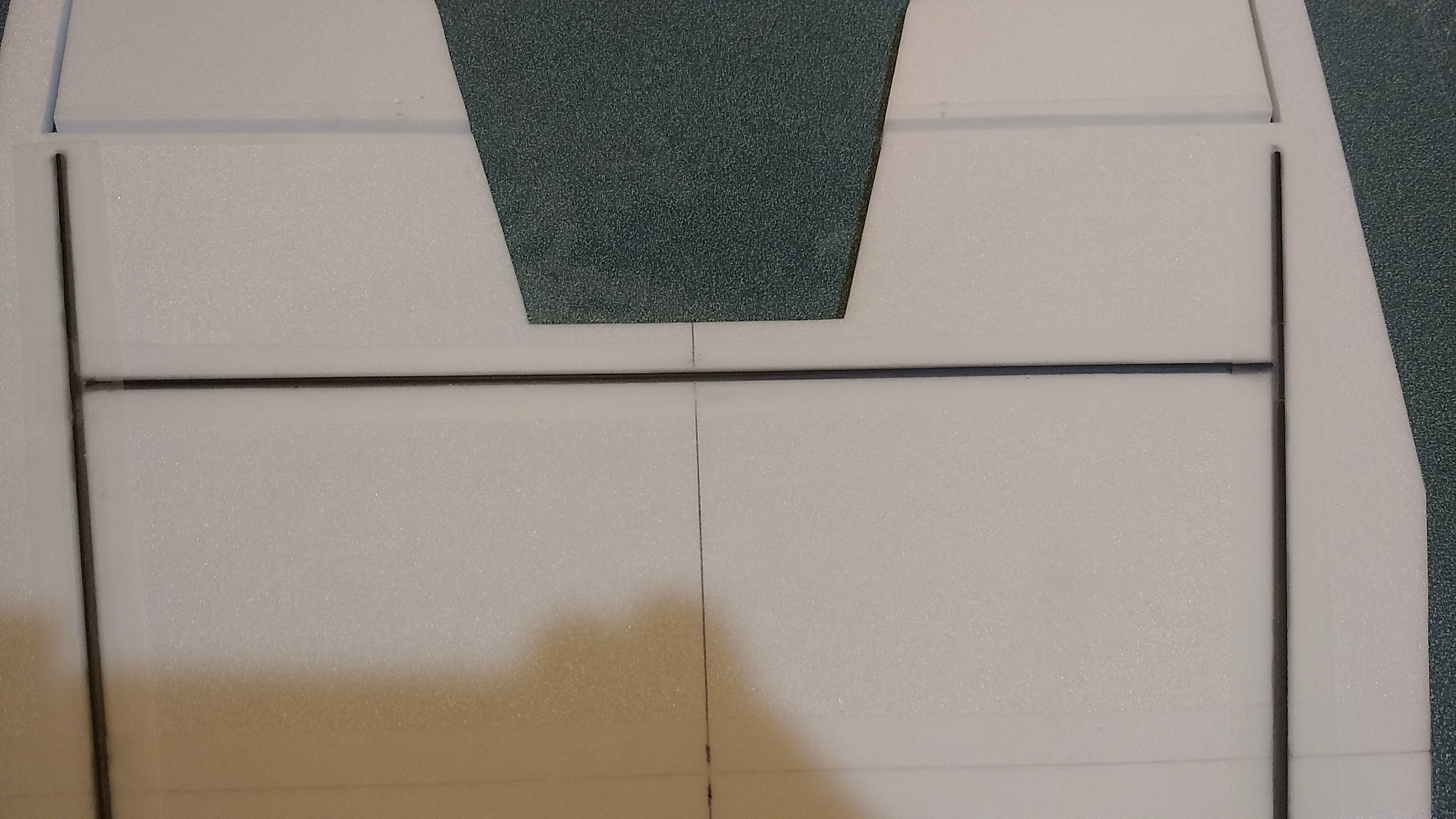
- Tape over middle cross spar.
-
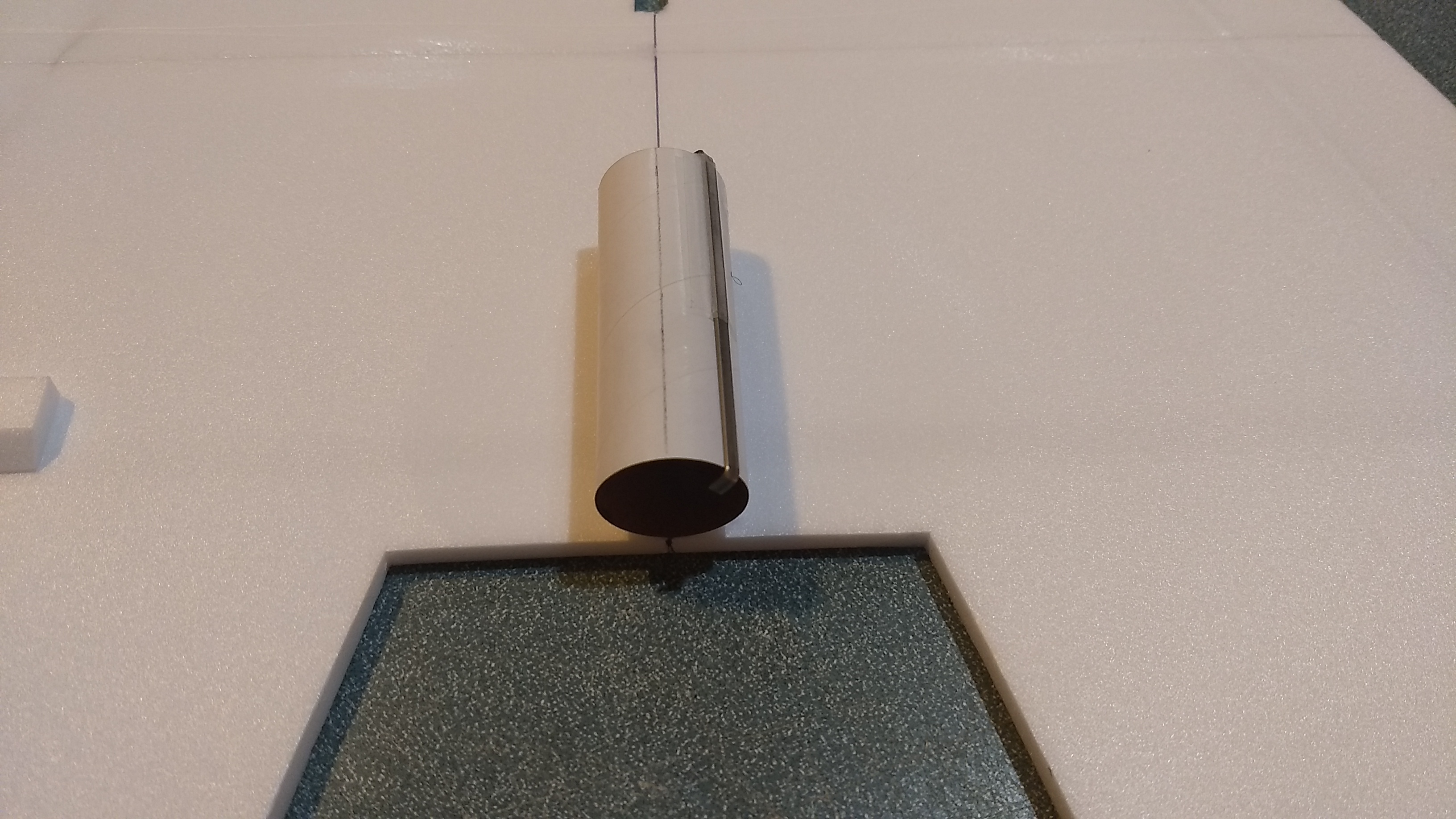
- Glue motor tube along line
-

- Glue reinforcing plates on either side of the motor tube.
-
- Glue the right and left wing tip gussets, gusset is flush with the rear of the wing.
-
- Sand the gusset/wing tip to make sure it is flat
-
- Glue the vertical stab against the gusset/wing tip, front of stab is even with front of wing tip.
-
- Round/profile the front of the wingtip to blend it into the wing
-
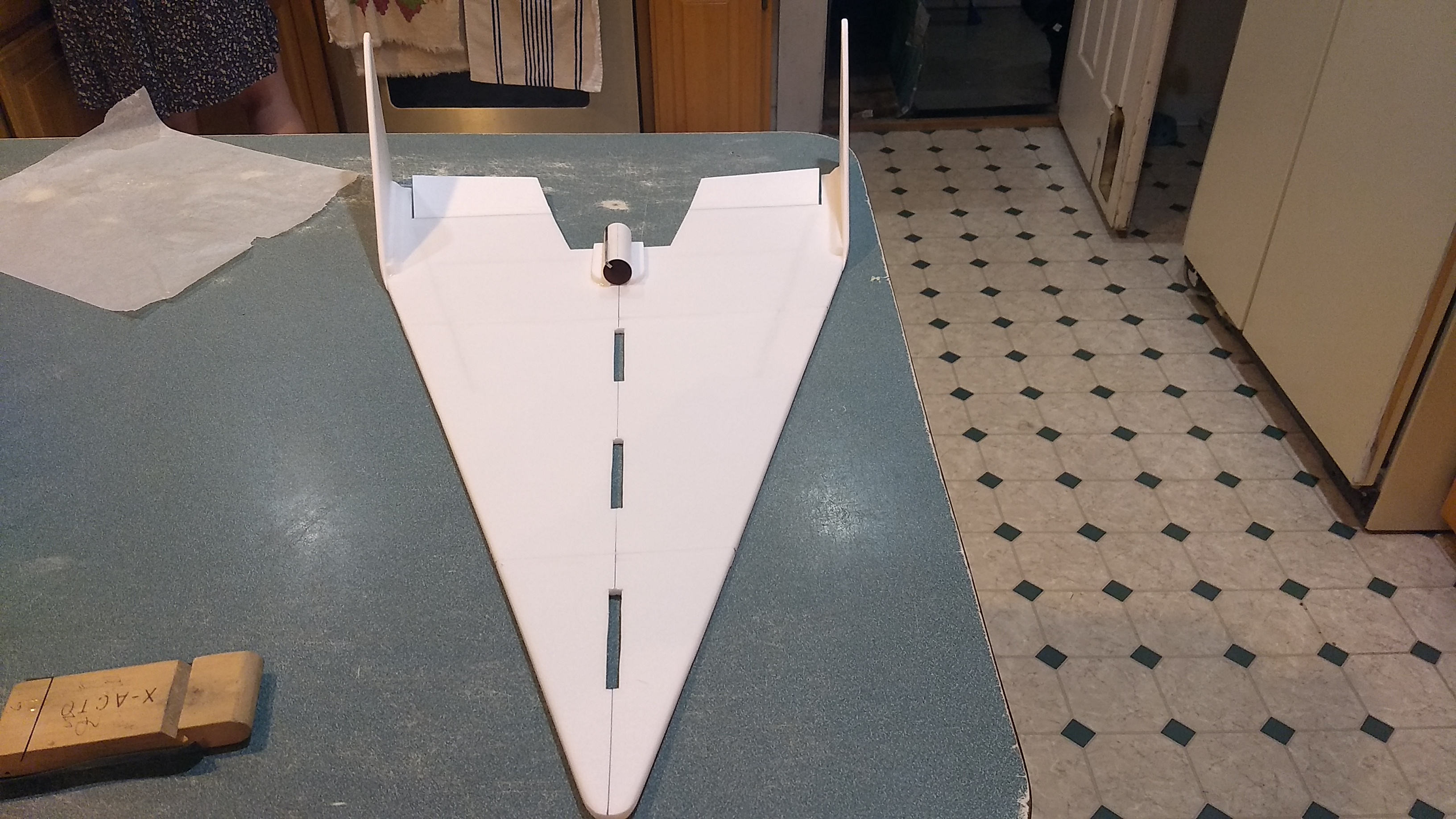
- both stabs glued in place.
-
- Glue a styrene plate onto each side of the fuse centered over the two pre-made holes
-
- Install a T-nut into each plate
-
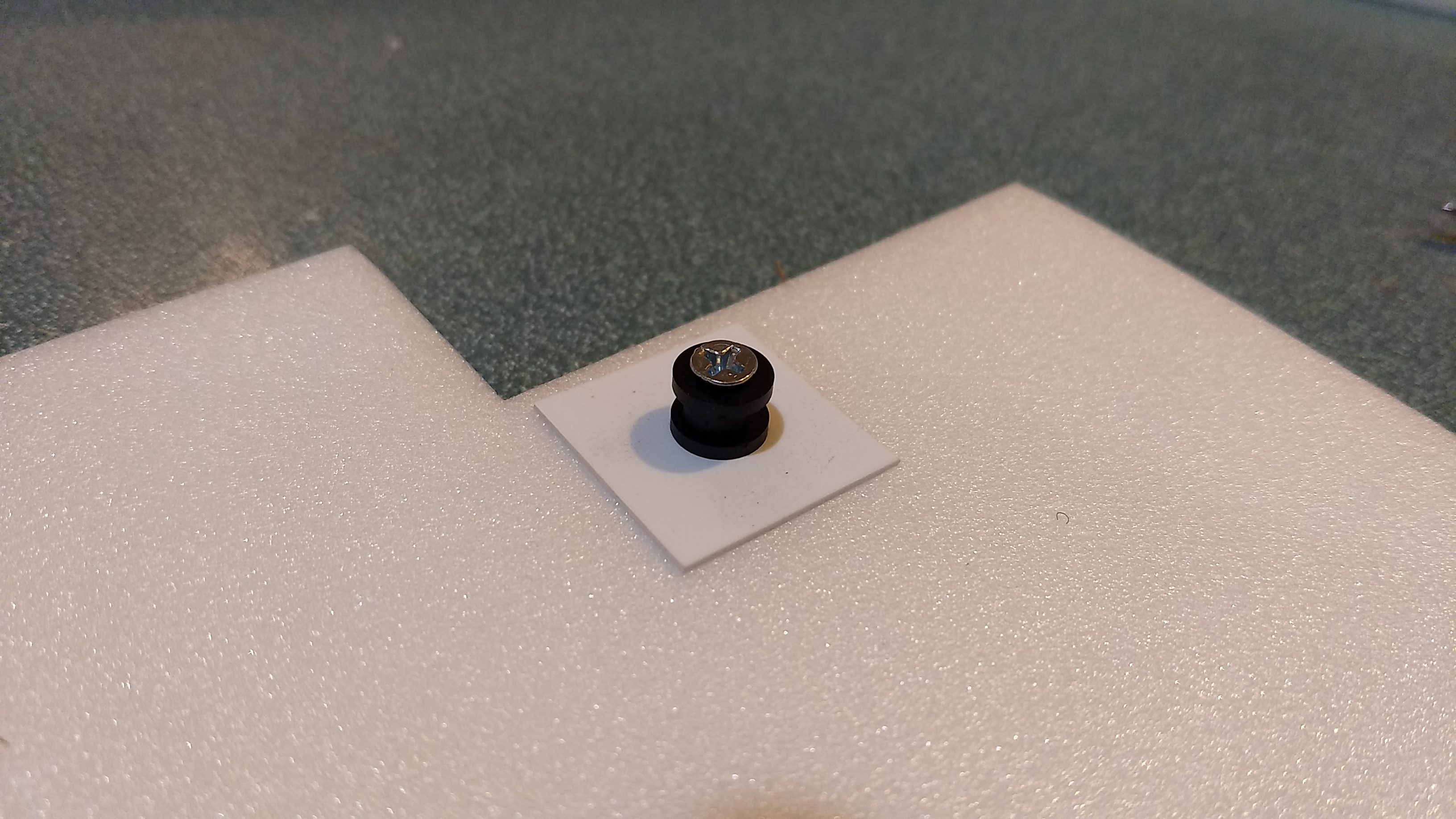
- then install the rail button and screw into the other side.
-
- Test fit then glue the vertical fuse profile in place.
-
- Flip the wing over and glue the bottom keel in place
-

- Completed airframe.
-
- Glue servo horns in place
-
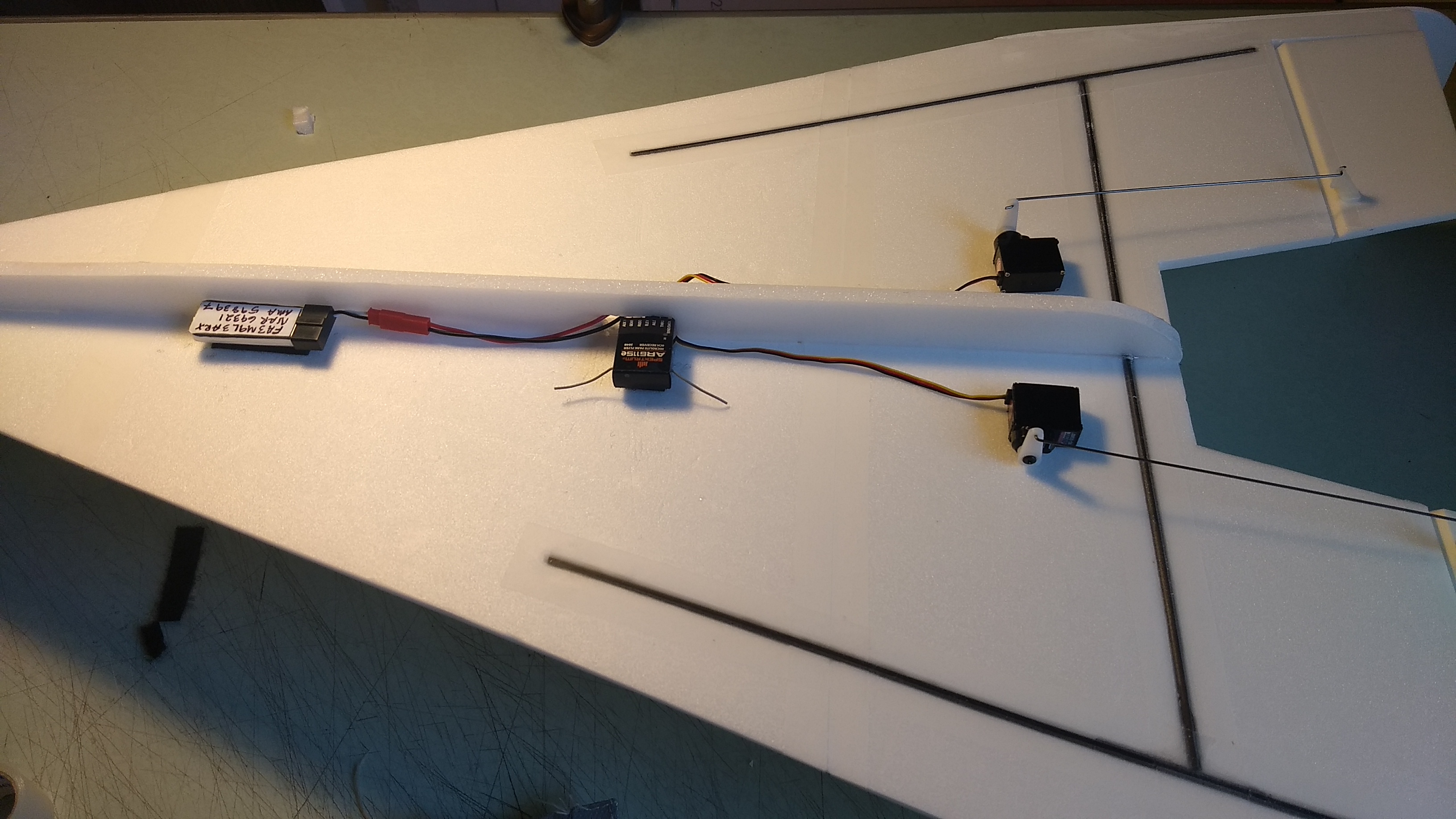
- Glue servos in place and install receiver/battery using velcro, tape wires down when satisfied.
-
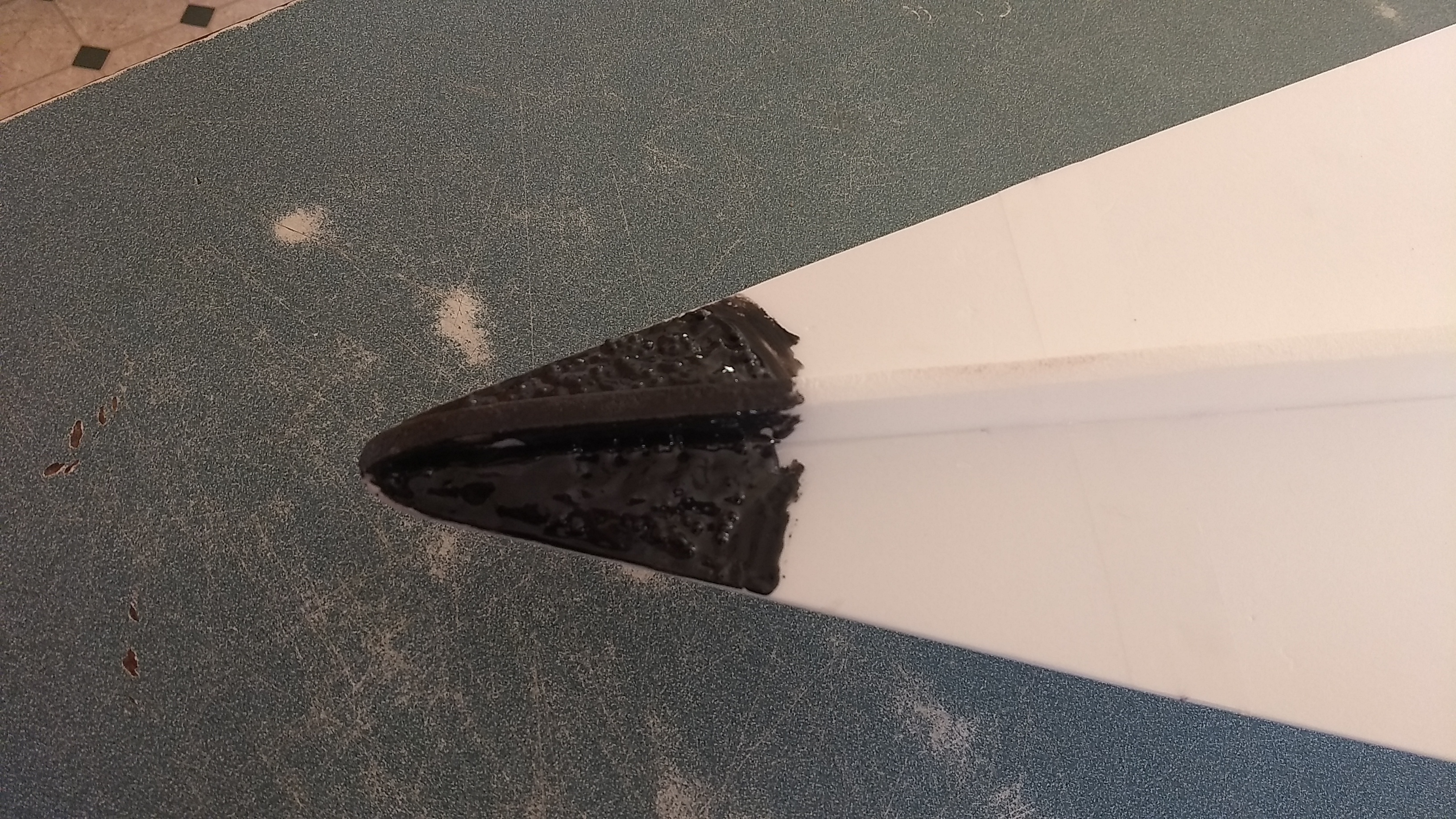
- Adding epoxy/shot to the nose for balance before painting.
-
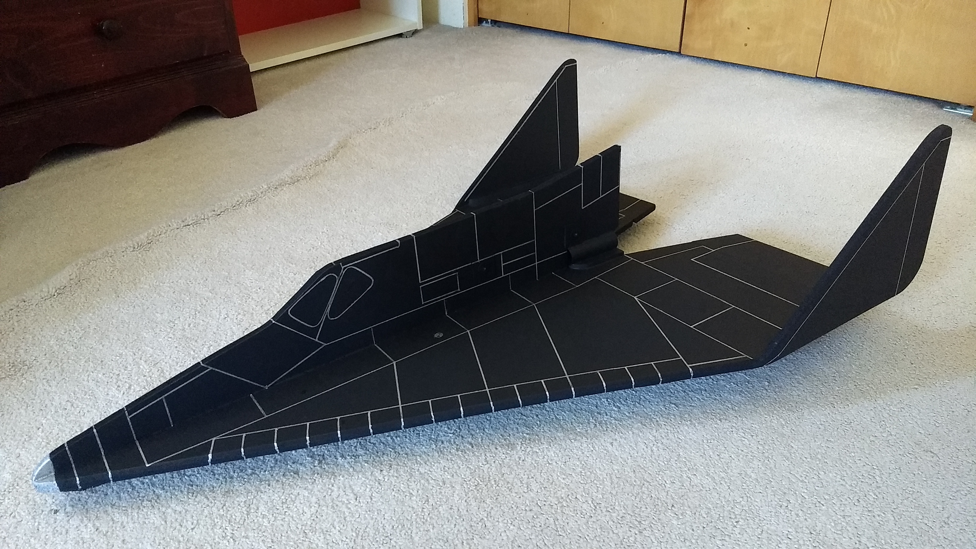
- completed model
-
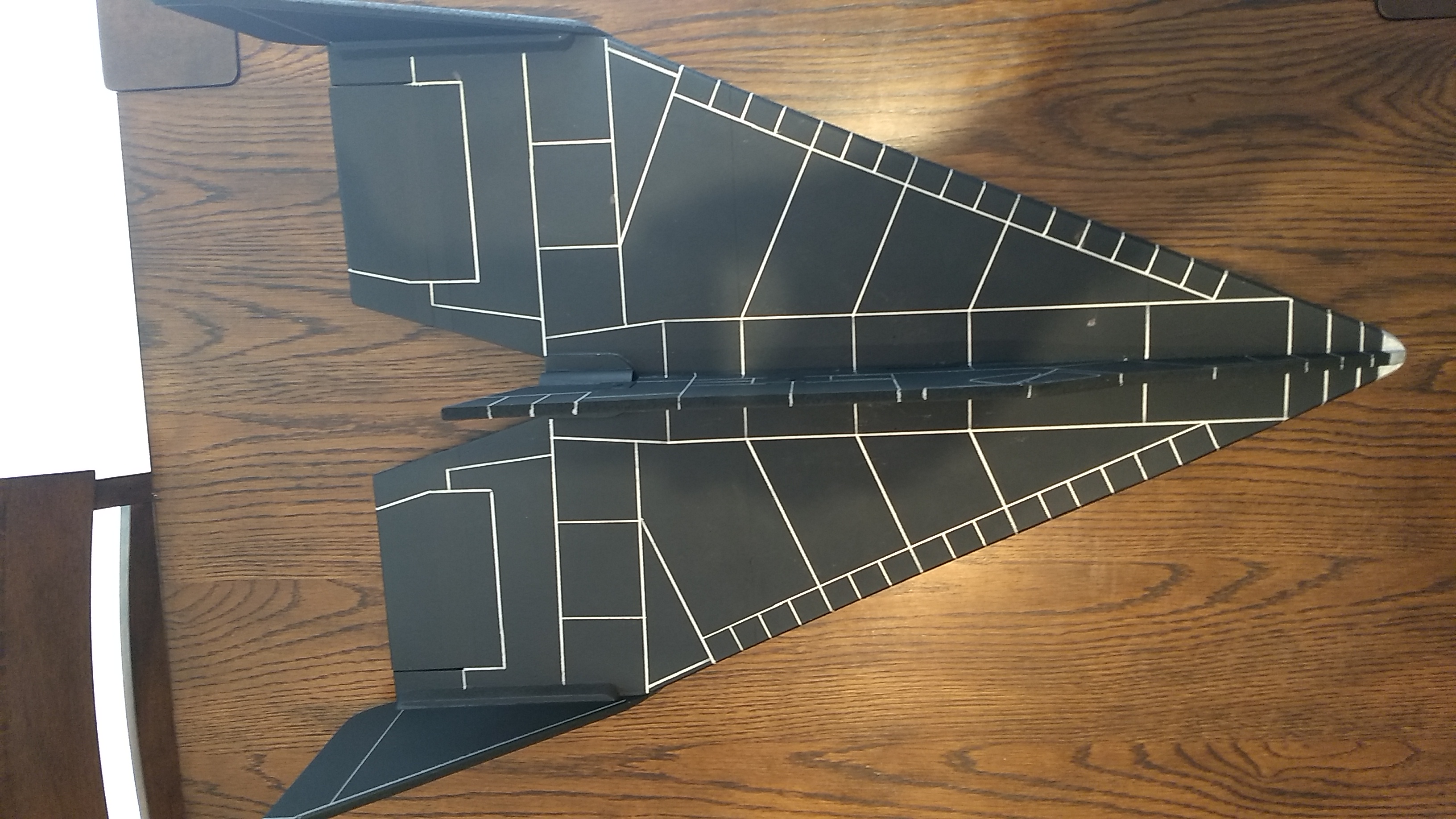
- Top view
-
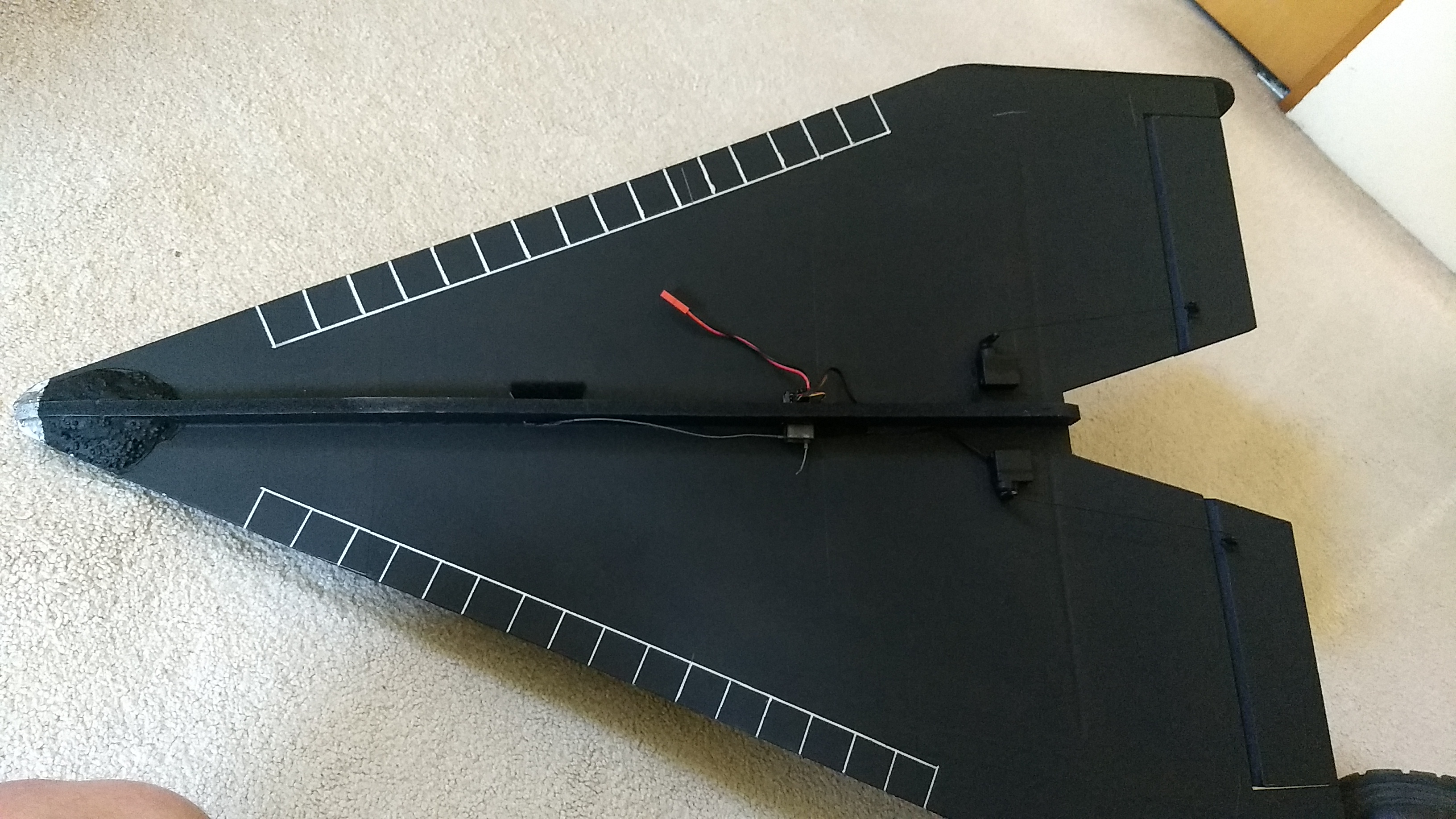
- Bottom view showing how little of the components are visible.
-

- X-20 3-view