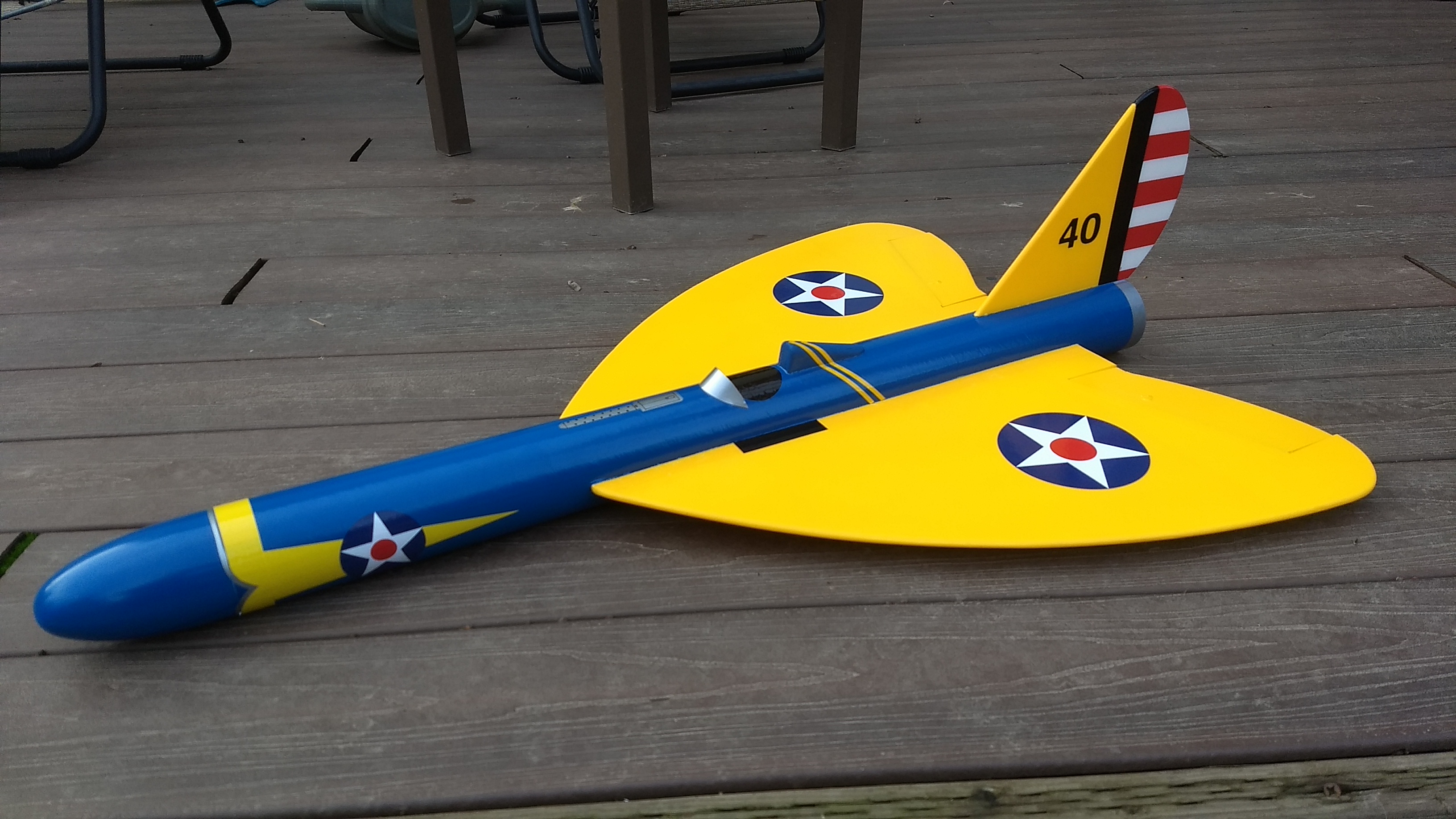
The Peashooter RC Rocket glider kit is the Army Air Corps answer to the german Iron Cross Rocket powered mid wing monoplane interceptor. It has a graceful post war style swept wing and vertical stab, and an open cockpit with headrest. It comes with a plastic nose cone, 2.6″ white tubing for the body, Depron wing and 6mm depron tail surface. The wing is pre-grooved for the spar, control surfaces are pre-hinged, and the body tube is pre slotted for the vertical stab and wing. Please refer to the General information for all kits tab above, then read these instructions completely before starting assembly. 33″ long, 23″ wingspan, 10.75-11 oz rtf.(painted) High quality cut vinyl decals available HERE. There is an option for the iron cross and peashooter decals at this link, select peashooter.
CG location for rocket flight: 13 3/4″ forward of the rear end of the body tube.
Unpacking your kit:
The kits are packed to protect them in shipping, but the contents are fragile so unpack carefully. Carefully cut the tape holding the tubes in the box, then unwrap/lightly cut the plastic wrap to free the tubes, the spar may be packed in the tubes and the baggie with the little parts and nose cone will be in the tubes as well. Carefully cut the tape holding the cardboard wing protector in the box and carefully remove it, don’t pull hard or bend it. Then carefully cut the tape holding the cardboard top piece to the bottom. There may be some sticky tape holding the cardboard to the bottom cardboard piece, carefully peel it being sure not to bend anything. Once the top cardboard is free you can see the foam wing/tail parts, there are little fragile pieces in here, so unwrap carefully. It may be best to use an exacto to lightly cut the plastic wrap and carefully remove it without cutting into the foam. Make sure everything is free before you remove the pieces to avoid breaking anything. Kits contain one or two scrap pieces for repairs if you damage anything in construction or flight, just cut and patch in a spare piece of the foam if needed using foam safe CA+.
Welcome to the world of rocket boosted radio control gliders. This is not a model for a novice RC pilot, but anyone who is comfortable with RC flying of a medium speed model should be fine. Read through the instructions, look at the photos and be sure you understand the step before committing to cutting or glue.
Identify all pieces, the kit should contain:
1 wing
1 Nose Cone
1 vertical stabilizer
1 wing spar
2 control horns/Pushrods
2 Body Tubes
Motor mount
Cardboard Windscreen
3 foam headrest pieces.
3 13/16″ x 2.5″ wide strips to center the motor tube
Velcro(for battery and rx/bec attachment)
2 Rail buttons with t nuts/screws
Blenderm Tape
Lead weight
Notes before starting:
Foam safe CA+(Bob smith super gold + is good) is the only glue recommended for construction. You will also need foam safe accellerator to set the glue.
You may use 220-320 grit sandpaper and a sanding block to slightly round the edges of the foam if you prefer before gluing the wing and vertical stab in place. Do any sanding before assembly.
Assembly:
- Glue the short body tube onto the coupler pre-glued into the long tube, there will be an alignment line/arrow mark, make sure that is aligned on both tubes so that the joint will be flush, the tube is cut by hand so by aligning these marks the joint will be matching.
- Unfold the wing and glue the center taped joint with CA+. Glue the spar in the slot, then when set, apply blenderm tape over the center joint and the spar.
- Test fit the wing in the wing slot, sand or trim as needed so it does not drag on the wing and make grooves in the foam. Note, the tail slot is at the rear and should be UP, the wing spars should be not be visible since they are on the bottom of the wing. Make sure the wing is centered at the front and rear and glue it in place. The body tube may tend to flatten somewhat around the slot, so you may need to squeeze the tube a little as you glue to make sure the tube stays round as you glue it in place.
- Glue the vertical fin into place and make sure the vertical fin is straight up and down using a triangle or something similar. Apply a light filet to both sides of the vertical stab on the inside and outside of the body tube.
- Glue three 2.5″ long foam strips on the motor tube using foam safe CA+. These help center the motor tube in the body tube once you insert it into the body tube. Note the tabs will be on the sides and bottom of the tube, the fin tab will make contact on the top of the tube. Refer to the picture.
- Test fit the motor mount into the body tube and under the fin tab. Make sure it fits, or sand the foam tabs lightly. Glue the motor tube in place, it will inset about 1/4″ from the end of the body tube. Put a fillet on each side of the motor mount tabs and fuselage, NOTE*** the motor hook is glued at the front, make sure you have the front forward when you glue it in place. Make sure the vertical stab stays vertical.
- Glue the three headrest parts together, then sand the top round and sand the bottom to match the contour of the body tube by wrapping the tube with sandpaper and dragging the part accross the paper.
- The windscreen is made from cardstock included in the kit, curved to shape and glued to the fuselage around 4″ back from the leading edge of the wing.
- Glue the headrest about 2.5″ behind the windscreen.
- Note that there should be two holes on each control surface. Apply CA+ to each of the control horns and press them in place in the underside of each control surface into the pre-made holes. The control horn holes face forward and the pushrod should be closest to the body tube. Apply a fillet around the control horn on the the prongs on the bottom of the wing to lock them in place.
the basic construction of the airframe is complete.
Radio Installation
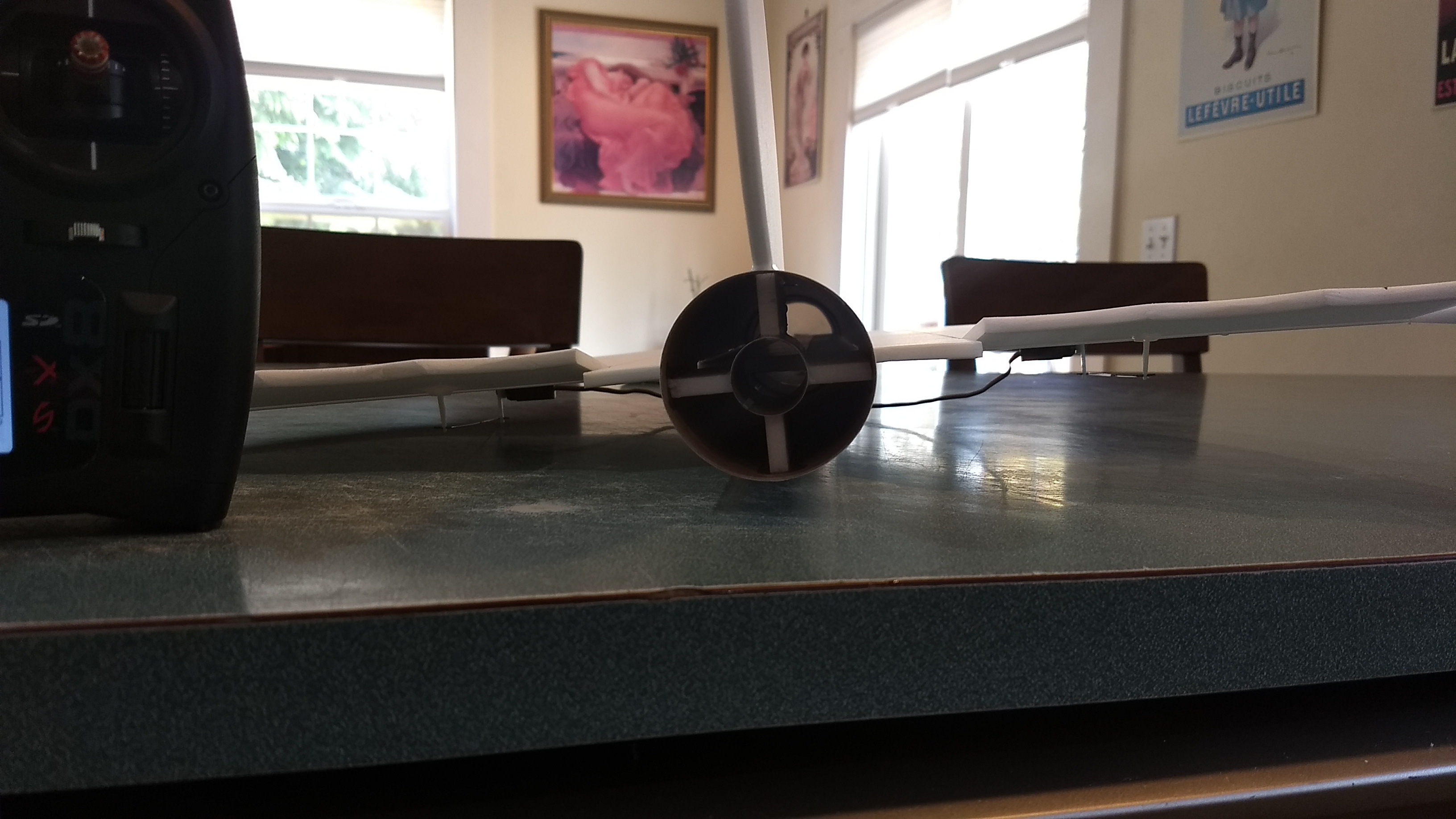
Note: Your radio needs to be configured for Delta mixing, this means that the servo arms will move the same direction during elevator stick movement and opposite for aileron stick movement. Connect your servos to the receiver one in the aileron connection and one on the elevator connection and apply power. Use a servo arm at least 9/16” long and with holes small enough that there won’t be slop with the pushrod wire when installed. I use the hole furthest out on the servo arm, to maximize movement. On some servos there are a long two-ended servo arm, you can trim off one end and use that arm to get sufficient length. Zero out any trim settings on the transmitter.
- Connect each servo to a pushrod. If the pushrod is too tight, you can use twist an X-Acto knife in the servo arm hole to make it larger, but be careful and do not make it too large. The servo should be next to the body tube on the bottom of the wing, with the servo electrical wire pointing forward and the servo arm pointing toward the wing tip. Hold each servo in place so that the control surfaces are centered. With the model right side up look at it from the rear. Moving the transmitter stick back(up elevator) should move both elevons up. Moving the transmitter stick to the right should move the right elevon up and the left elevon down. If you can’t get the servo reversing to give you the right polarity try swapping aileron/elevator inputs to the receiver or turning the servos over and swapping the servo arms to the other side of the output shaft. If that is correct, continue.
- The servos may be attached to the model using double back servo mounting tape(not included) or by directly gluing the servo to the wing with foam safe CA+. Double back servo tape can loosen over time and with exposure to heat, I prefer to glue the servo in place. With the radio still on, put a moderate amount of glue on the servo, being careful not to get any near the output shaft, and set it in place on the model next to the body tube keeping the control surface centered. Do the same to the other side. Make sure the glue is set before continuing. Note** The servo wire should point toward the front of the model. Apply a fillet of glue around the servo/wing to help secure it and let it cure being careful not to get any glue near the output shaft of the servo.
- Attach a 12″-18″ servo extension to each servo. You just need to be able to route the wire to the front of the tube to attach it to the receiver.
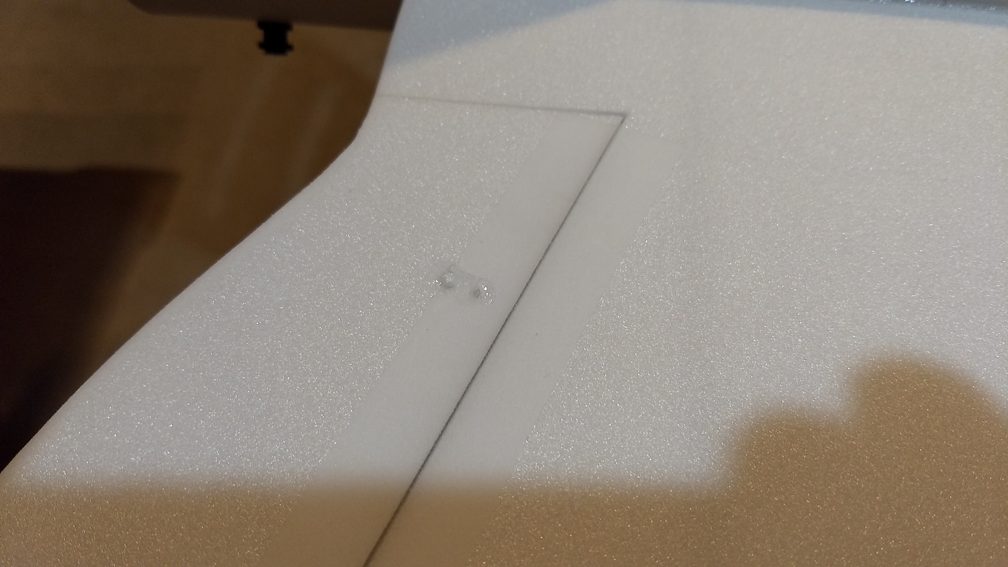
- Make a 1/8″ wide by 1/2″ long slot in the body tube on each side of the body tube near the servo and pass the wires through to the inside and toward the front. On my model I just made a U shaped cut, folded the cardboard forward, inserted the wire then folded the cardboard back over the slot/wire. I then glued the cardboard tab in place. See photo for more clarity. I taped the servo wires down to the wing using the blenderm tape.
- Re-Attach the servo wires to the receiver and make sure they are going the right direction.
- Make sure the control surfaces are centered, use trims if needed. Now measure the control surface movement. Full elevator movement should be 3/4″ in each direction, aileron movement should be 1/2″ in either direction. Sometimes the foam has a slight curve to it at the wing tips, it won’t affect flight performance. When setting the control surfaces for neutral use the middle of the wing as your guide for what is level.
- If you have a flap/elevator mix you can program up elevator trim for boost and glide. If you can’t set the up elevator trim to a switch on your radio you’ll have to manually put in boost and glide trim using the trim tabs which is hard to do while flying the model. My model needed slight down trim for boost and about 3/16″ to 1/4″ of uptrim for glide.
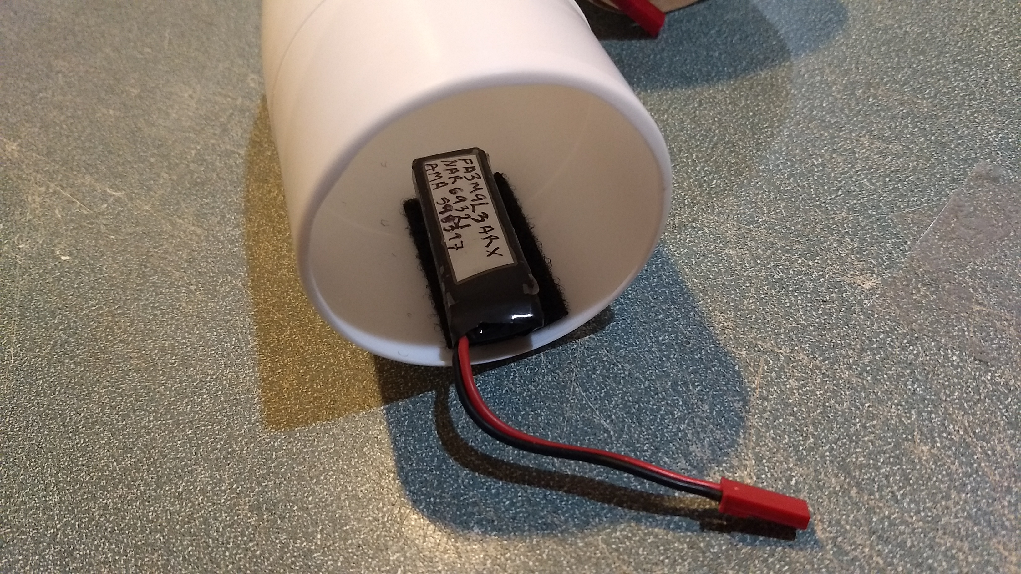
- Use the included Velcro to attach the receiver insde the body tube far enough in that the nose cone won’t hit it. This allows you to be able to remove and replace the receiver if needed for repairs or for removing the servo wires.
- I attached the battery inside the nose cone on the bottom of the shoulder with velcro.
- I can only recommend testors/model master enamel spray at this time, others I’ve tried damage the foam surface. I used Testors gloss Yellow and bright blue. **Note whenever you paint on the depron, if you mask or apply tape to it, it will pull up some of the paint. Minimize the actual painted surface you apply tape directly to to avoid this or do a paint scheme that allows you to mask the white depron surface and not mask over the paint. If it does pull up you can just touch up using a brush. You can use any color scheme you wish, inter war, or ww1 style allied markings would look good.
- Balance the model after painting and decal installation as this adds tail weight and will change the CG.
- Install the receiver and battery
- Insert your heaviest loaded rocket motor into the motor mount
- Support the model upside down at the balance point indicated for boost. Glue pieces of the included lead weight in the nose or tail as needed to balance it. Do not try to fly the model too nose or tail heavy. Remember, a nose heavy model flies poorly, a tail heavy model flies once
- Flying: See the General Instruction link at the top for flying instructions. Be ready on the first few flights to keep the model straight till you have the trims set perfectly for boost and glide.
The photos below are for reference but please read through and follow the steps in order as the text is written.
-
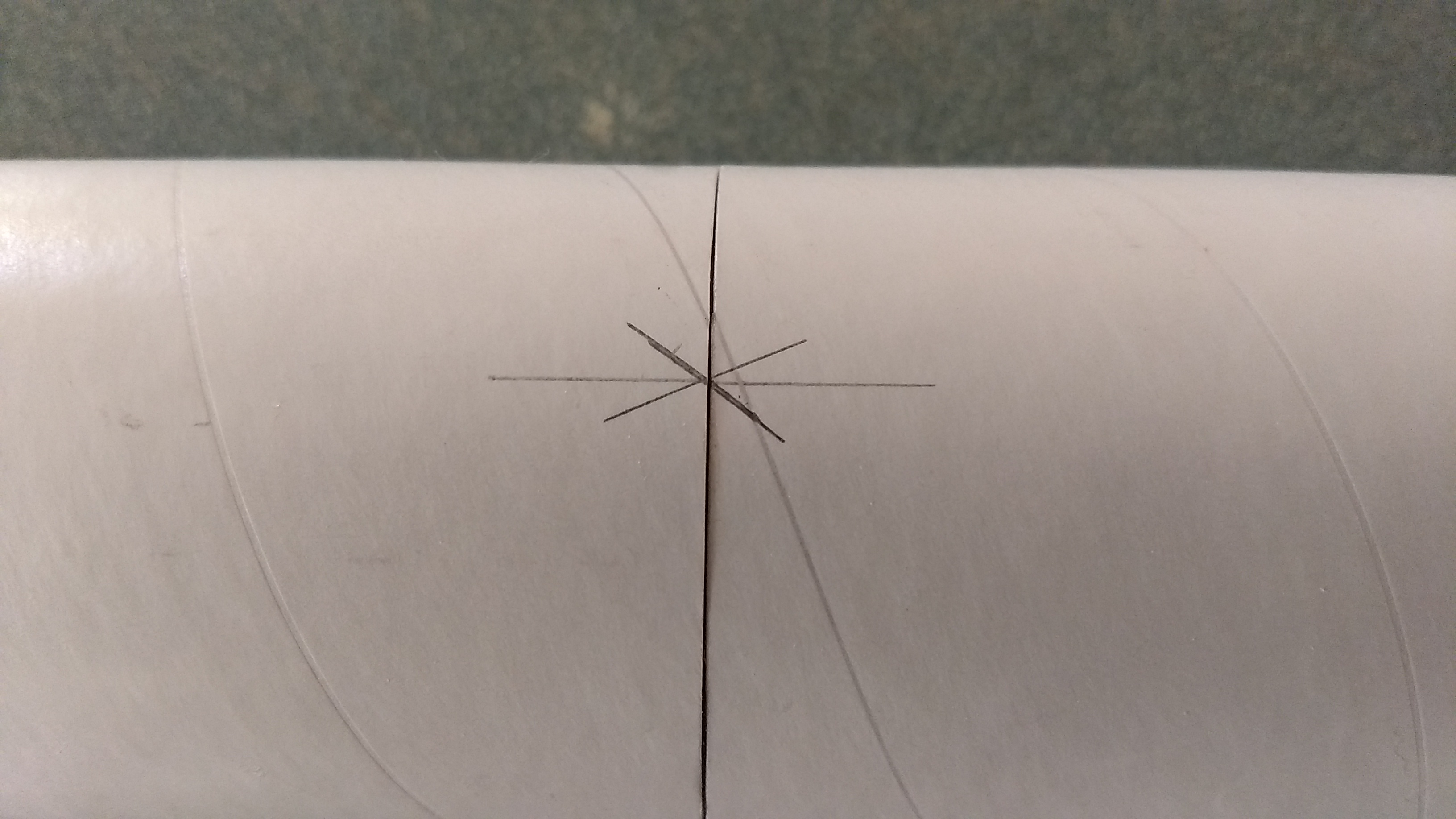
- Join the two body tubes so that the arrow alignment marks align.
-

- Glue the wing center joint
-

- Glue in the spar
-
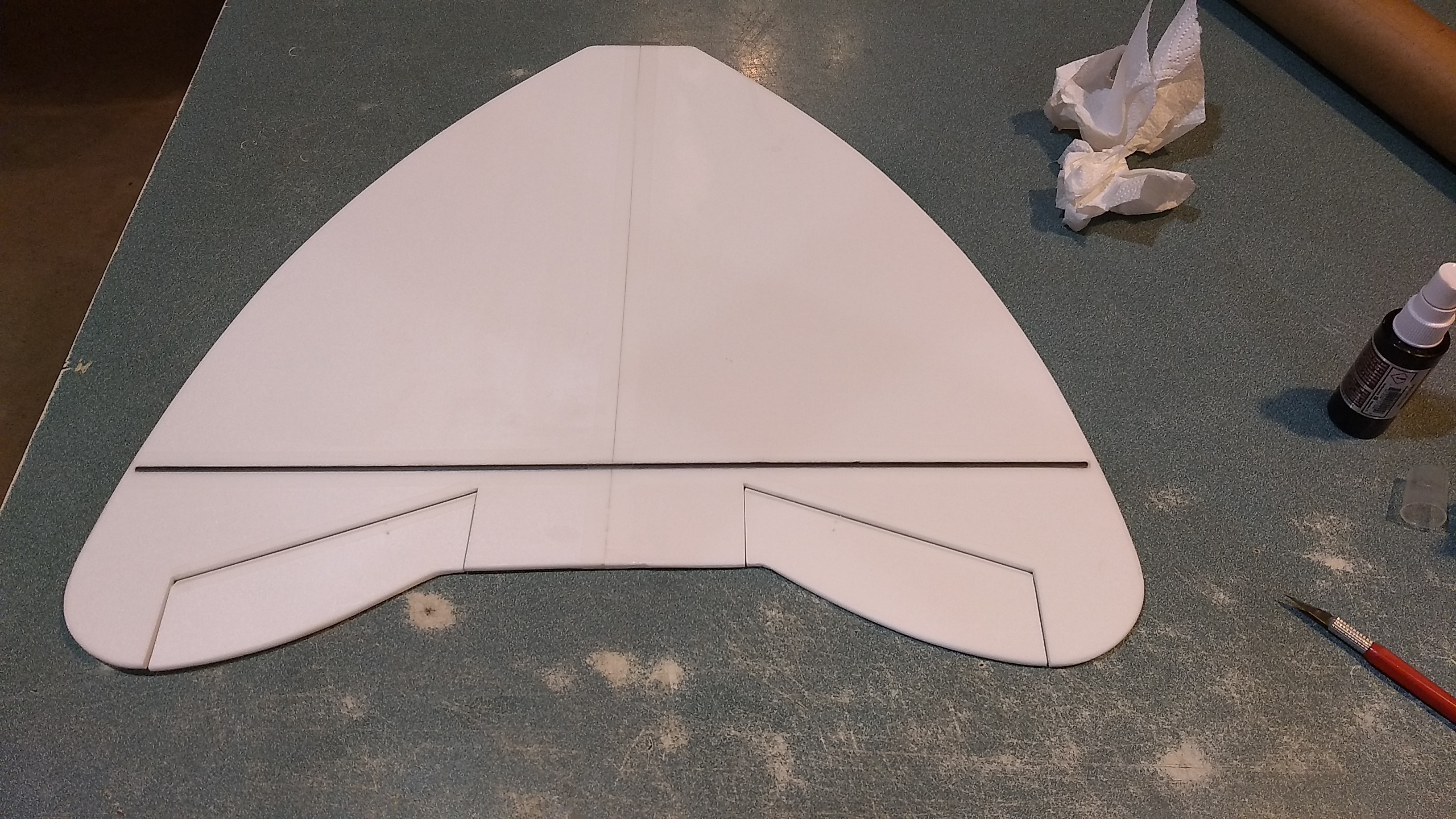
- Tape over the spar and center joint
-
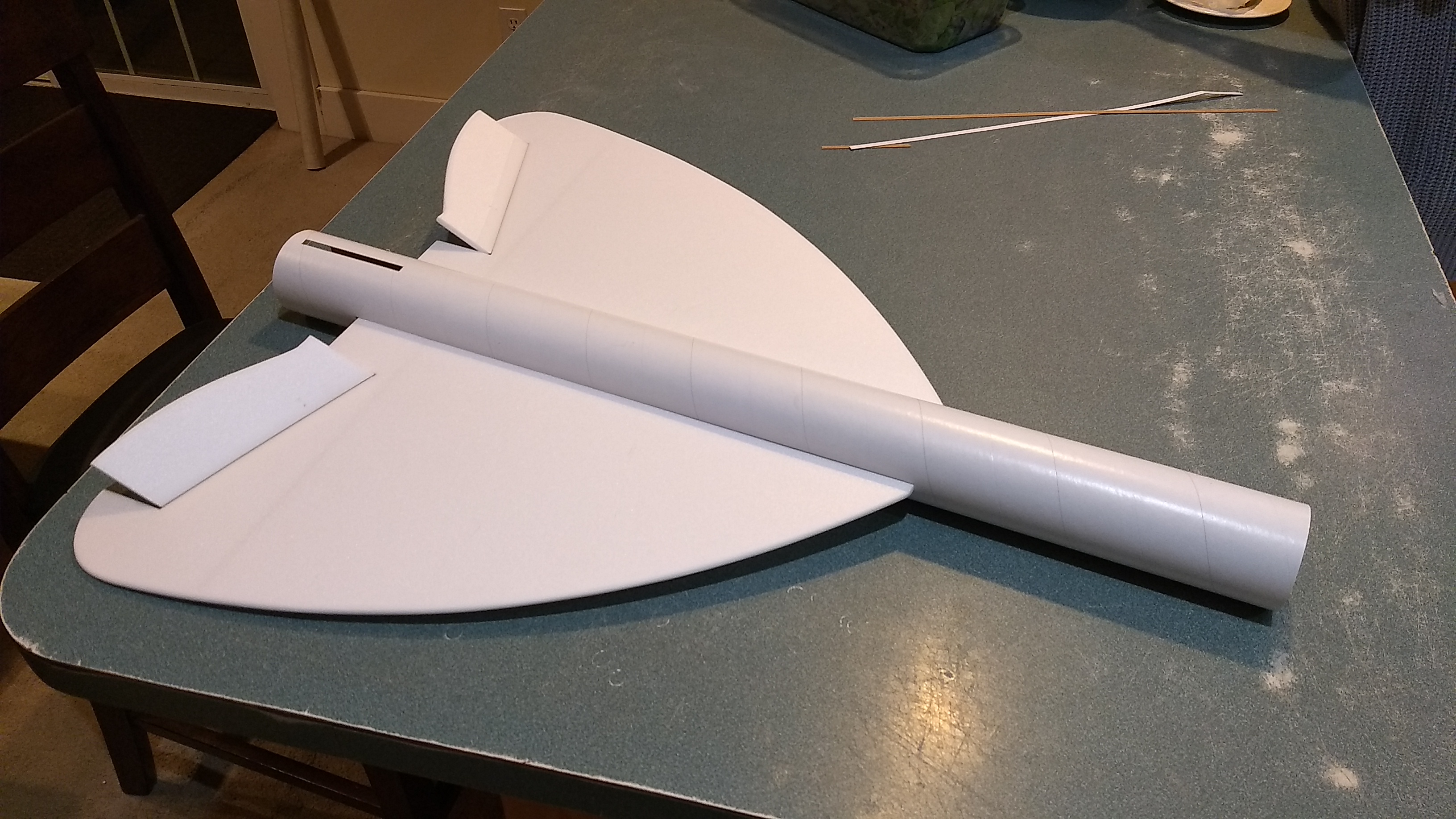
- Install the wing, and glue in place when centered, the front of the wing can be rounded to blend into the body tube after gluing.
-
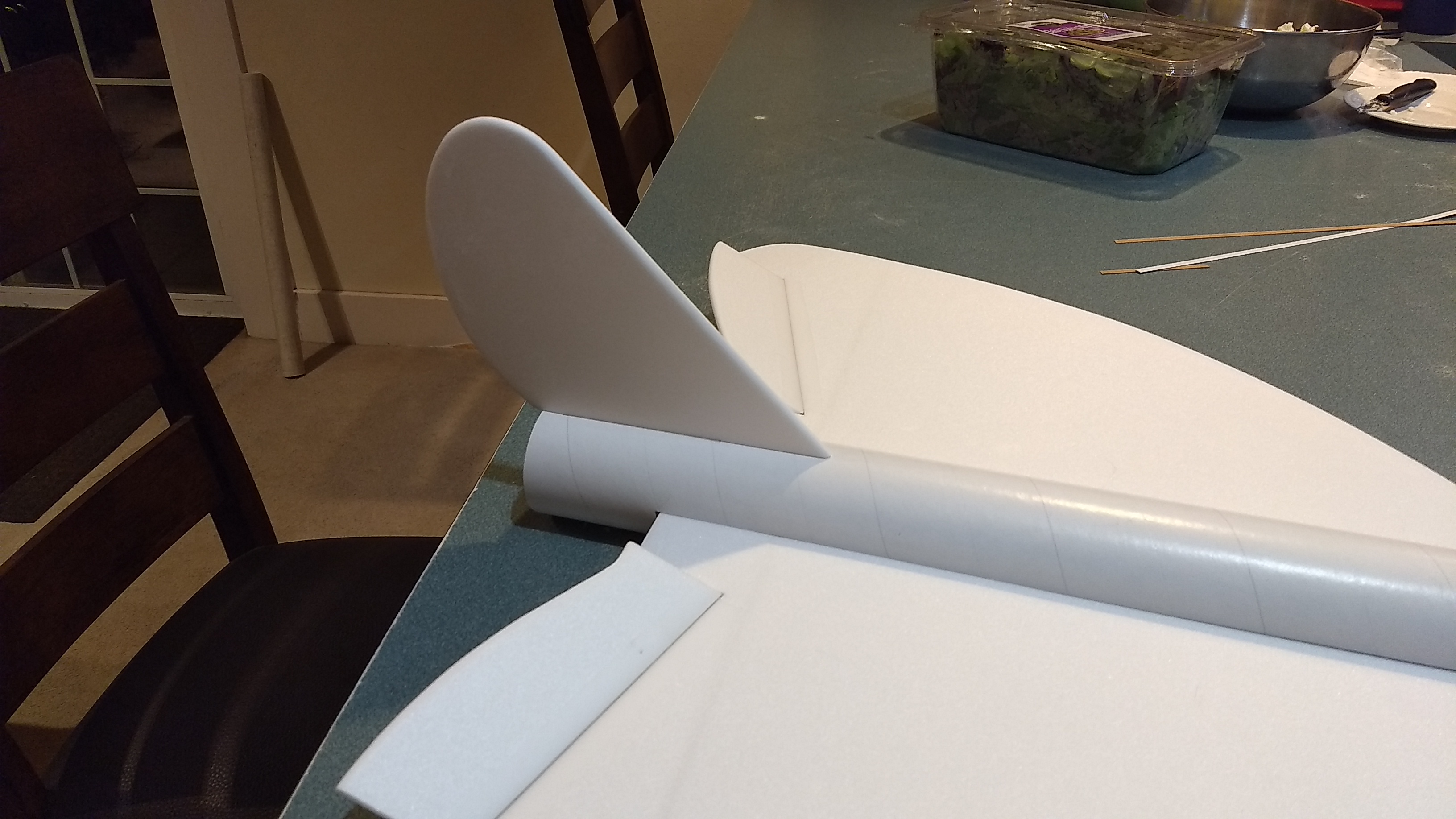
- Glue in the tail
-
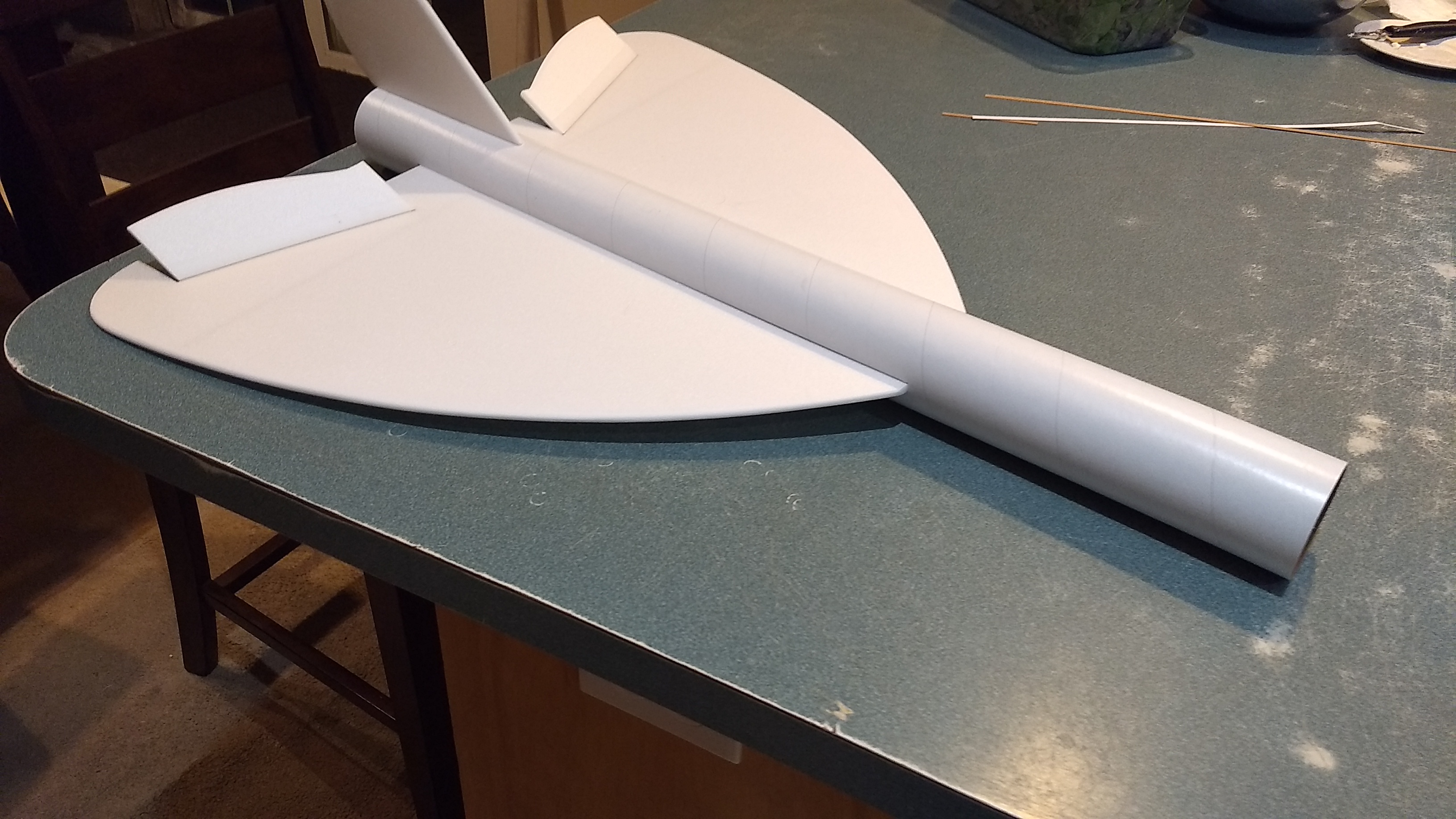
- Wing and tail glued in place
-
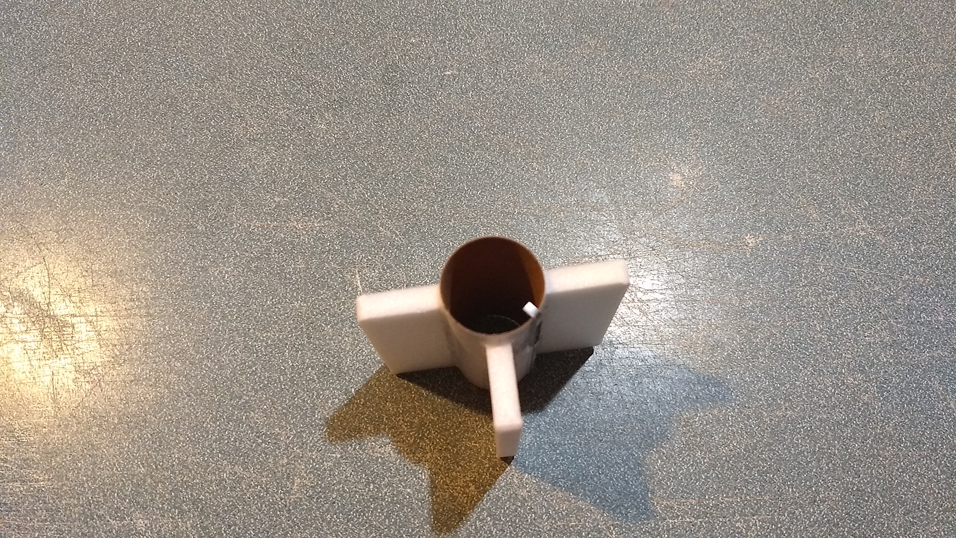
- Glue the three foam strips onto the motor tube on the lines marked.
-
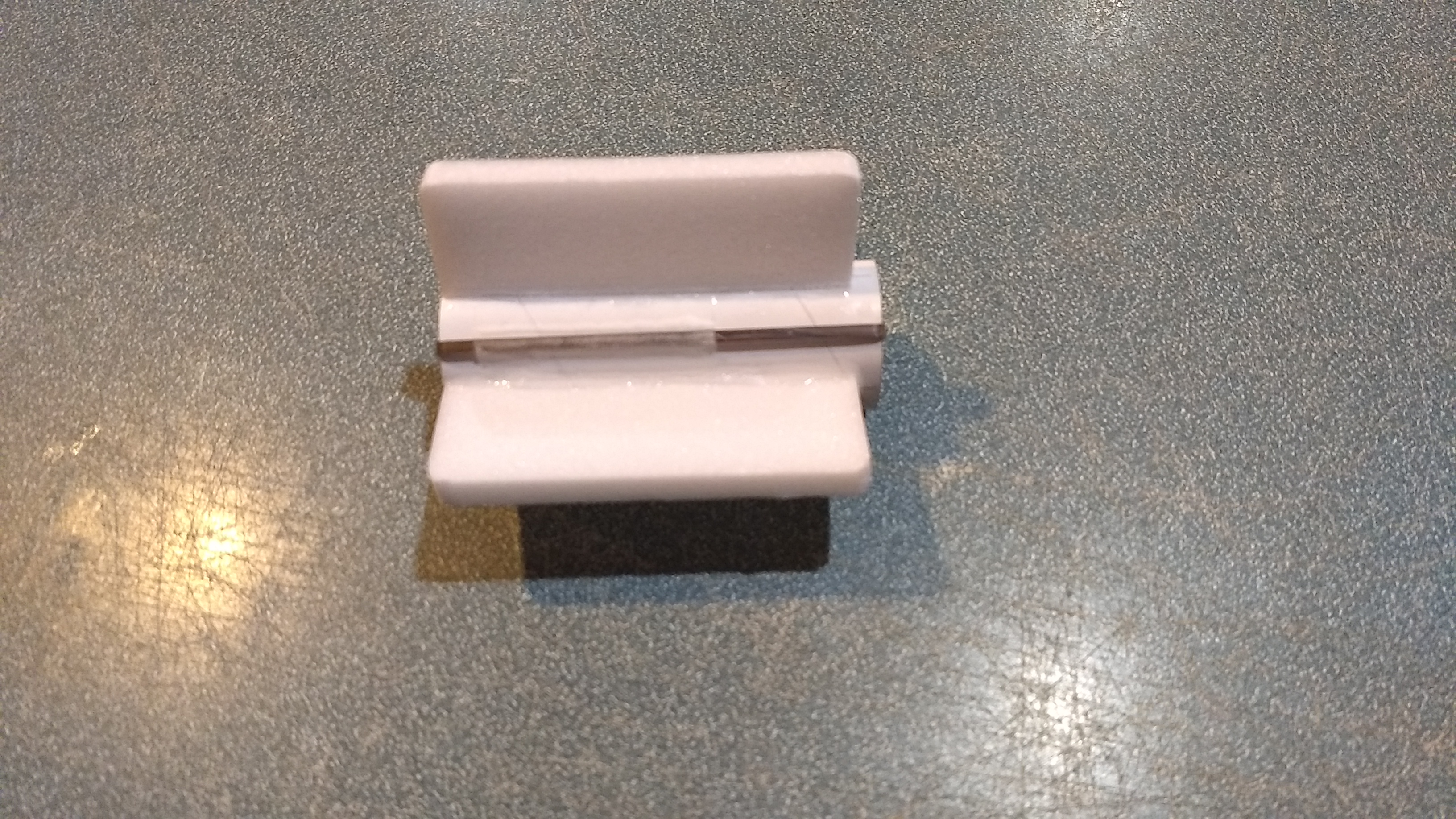
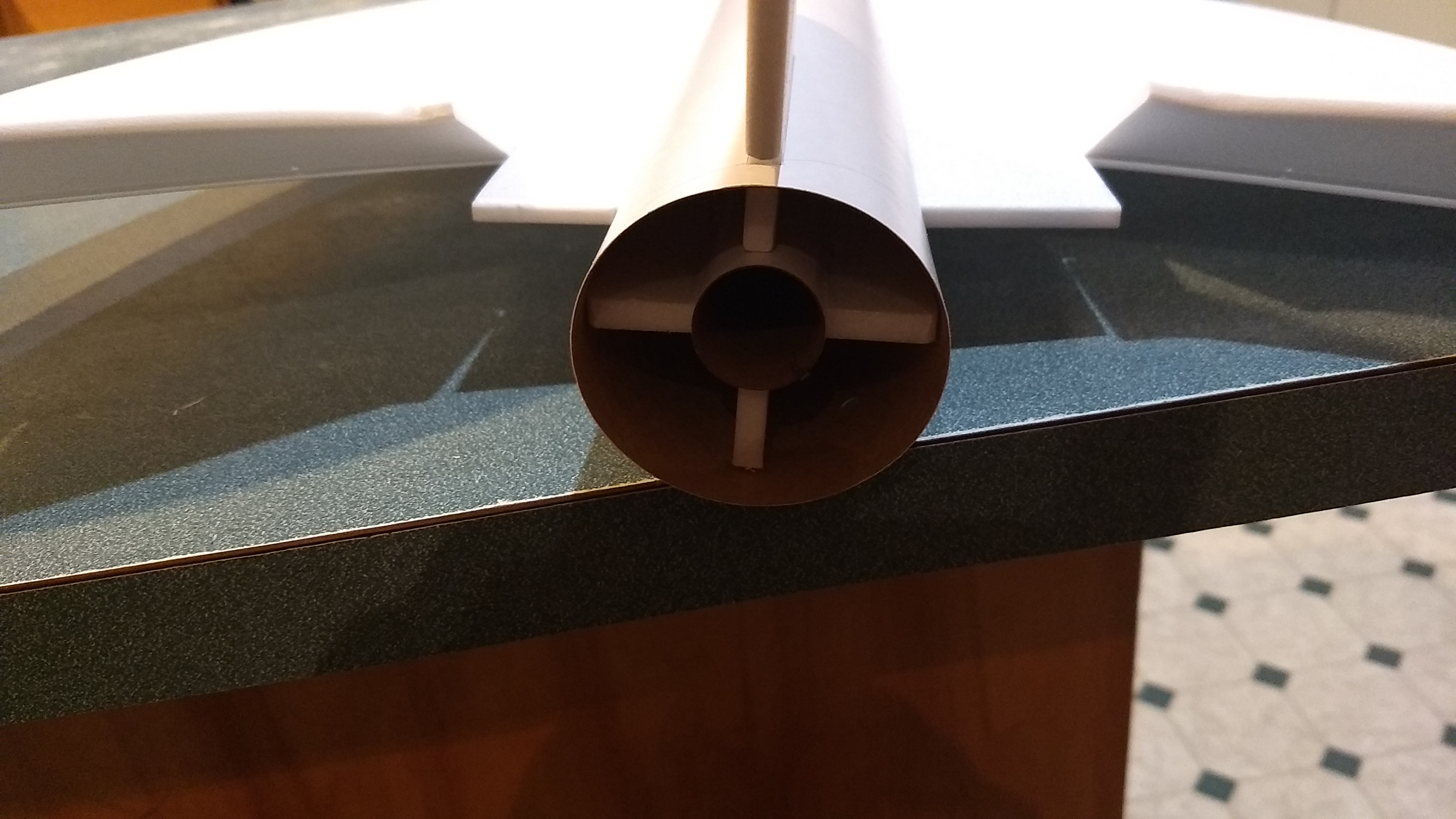
- Completed motor mount
-
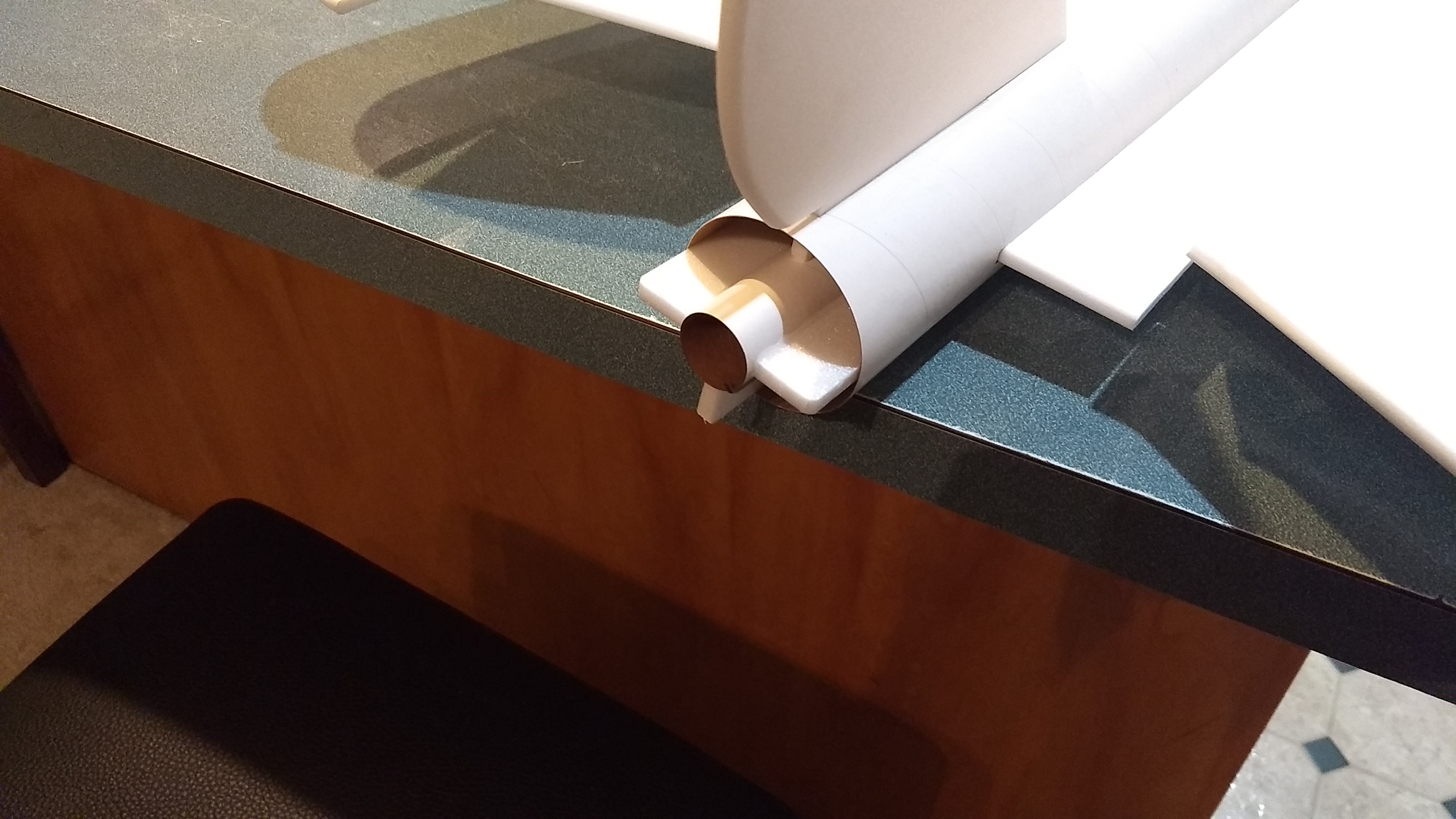
- Install the motor mount till it is recessed or flush with the rear of the body tube, you may need to sand and/or rotate it slightly to fit past the rail button and into the wing notch.
-
- Glue in the motor mount, insert till it stops, make sure the vertical stab stays vertical.
-
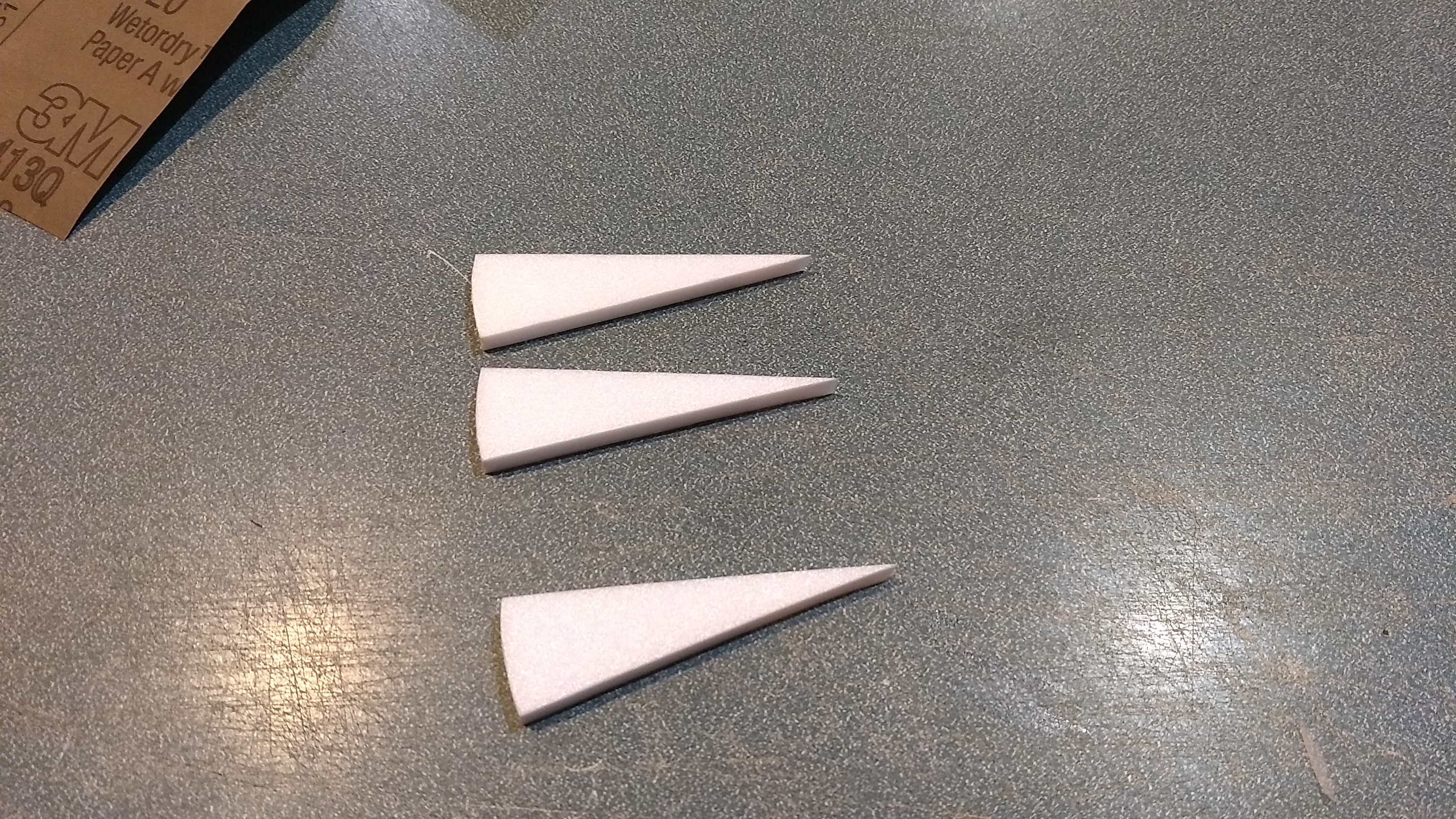
- glue the three headrest strips together
-
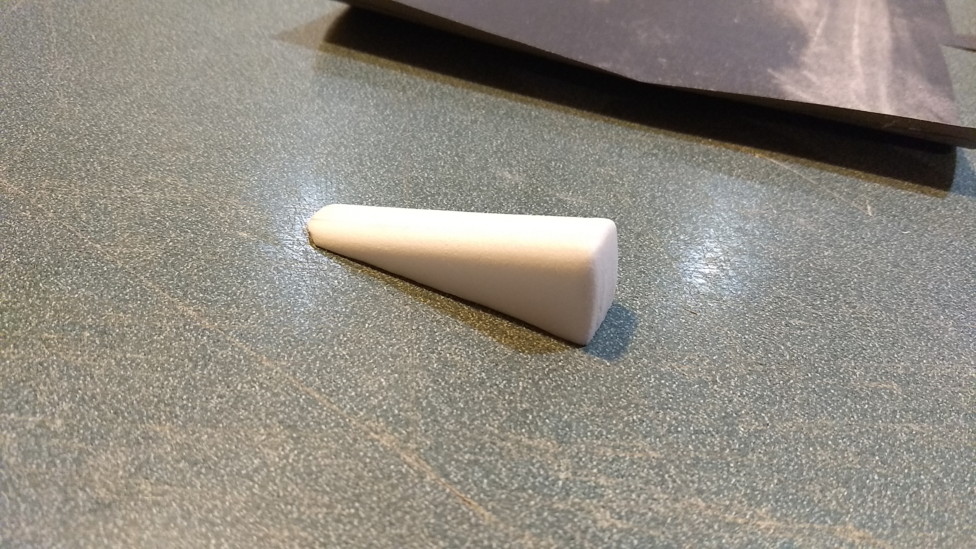
- Sand the headrest round
-
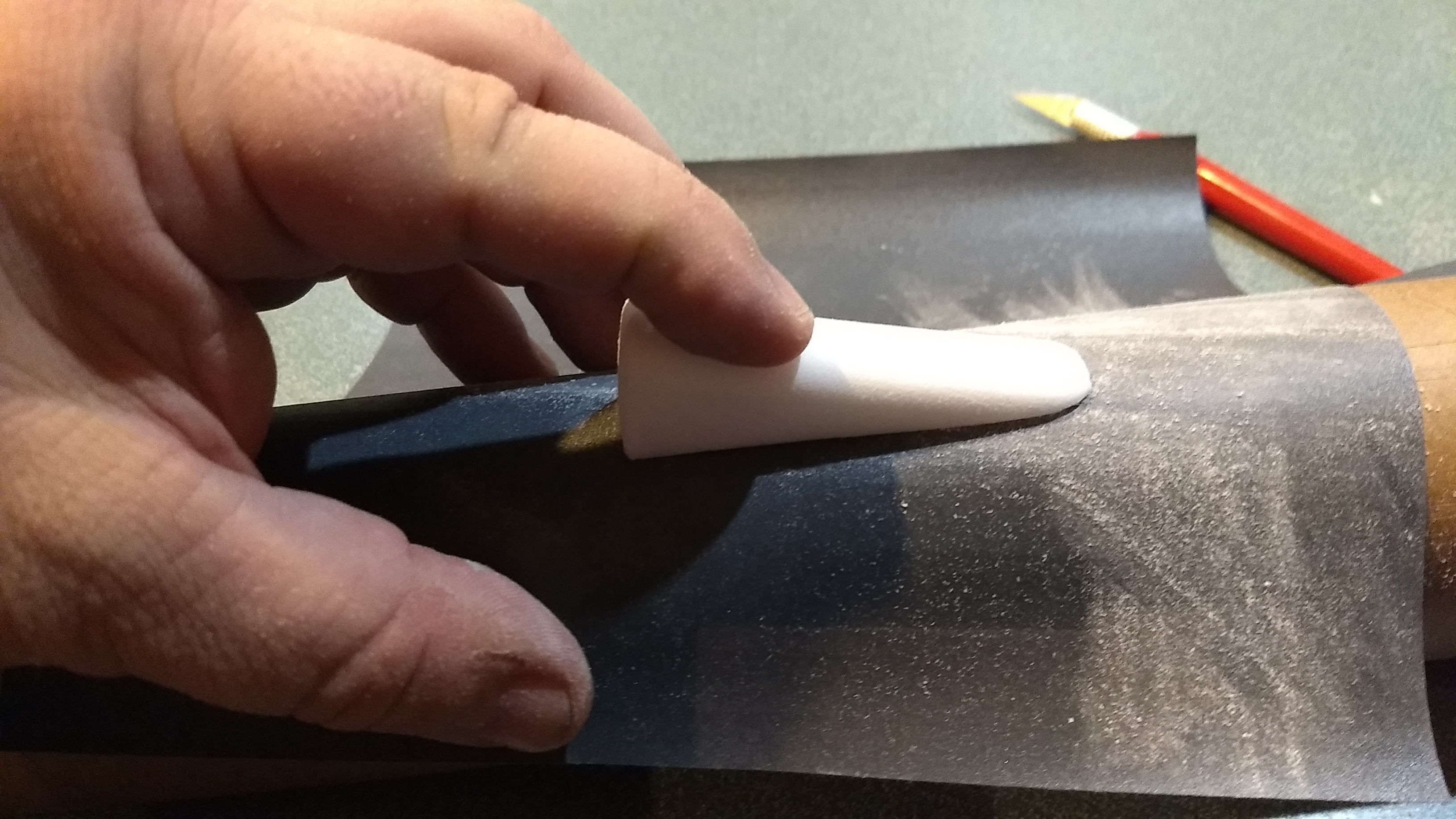
- Sand the bottom of the headrest to match the body tube contour
-

- Cockpit window glued approx 4″ back from the front of the wing. Headrest glued 2.5″ behind the windscreen.
-
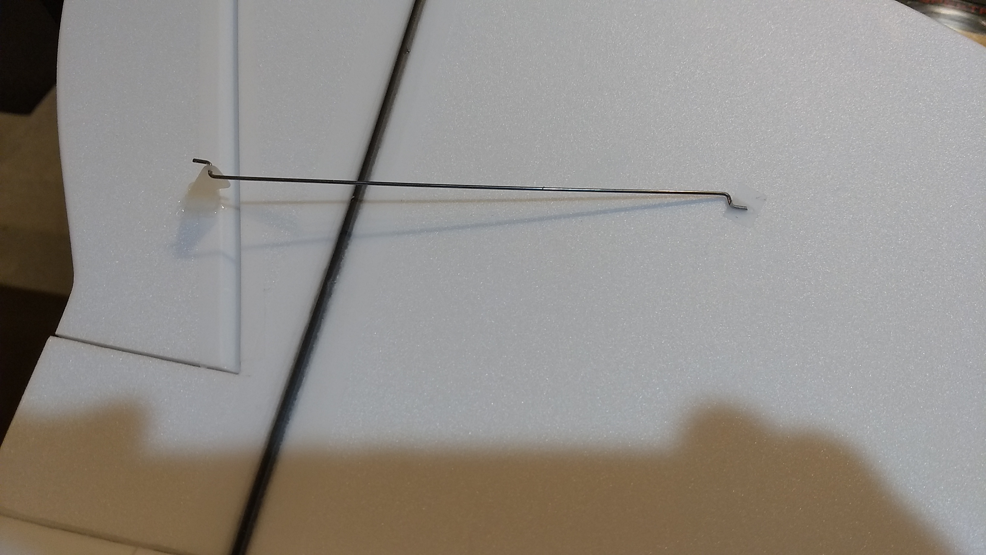
- Glue in the pushrod/control horn
-
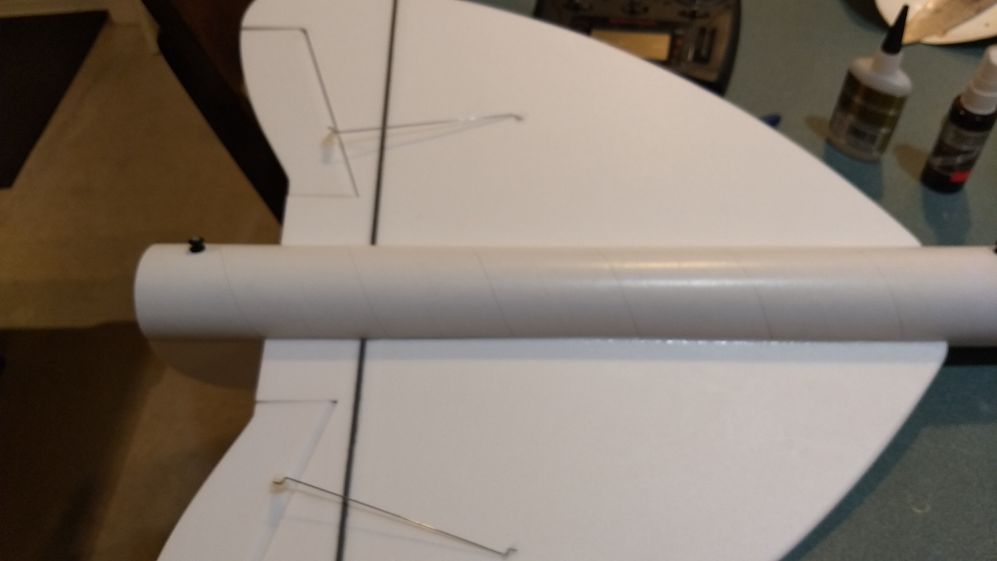
- Glue in the other control horns/pushrods
-
- Glue the top of the prongs of the control horns to lock them in place.
-
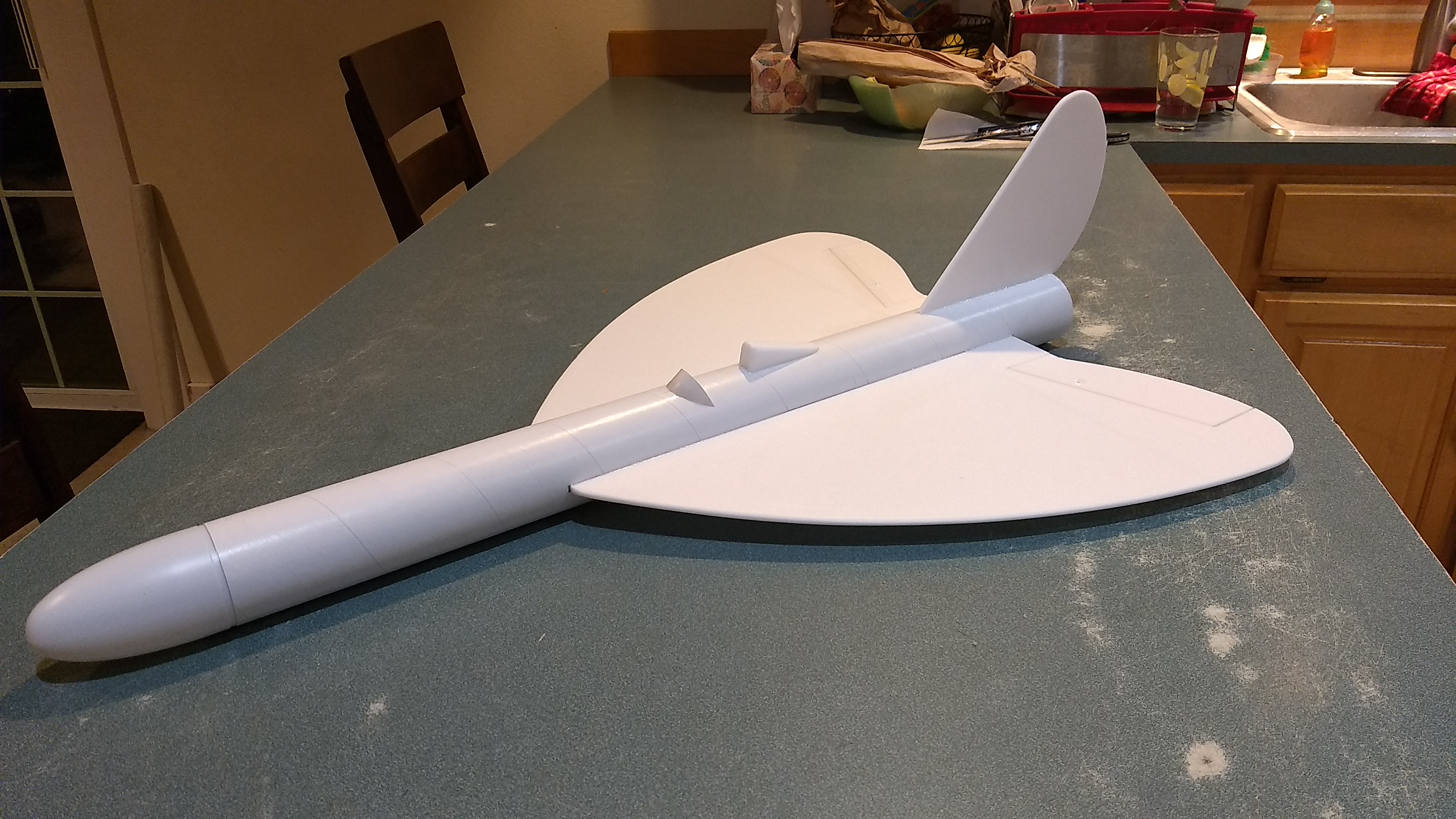
- completed airframe
-
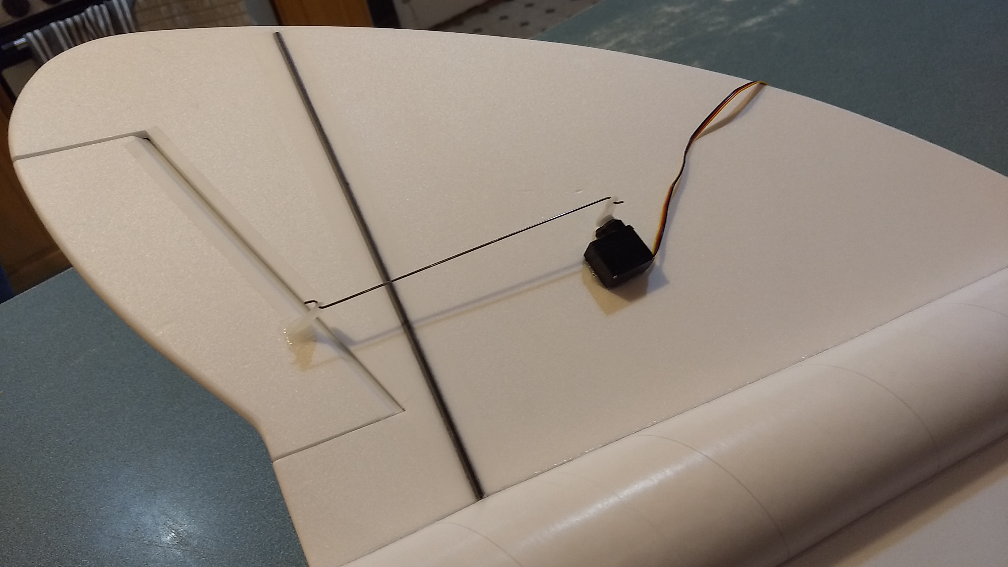
- Install the servos, note the orientation of the servo horn and servo electrical wire pointing forward.
-
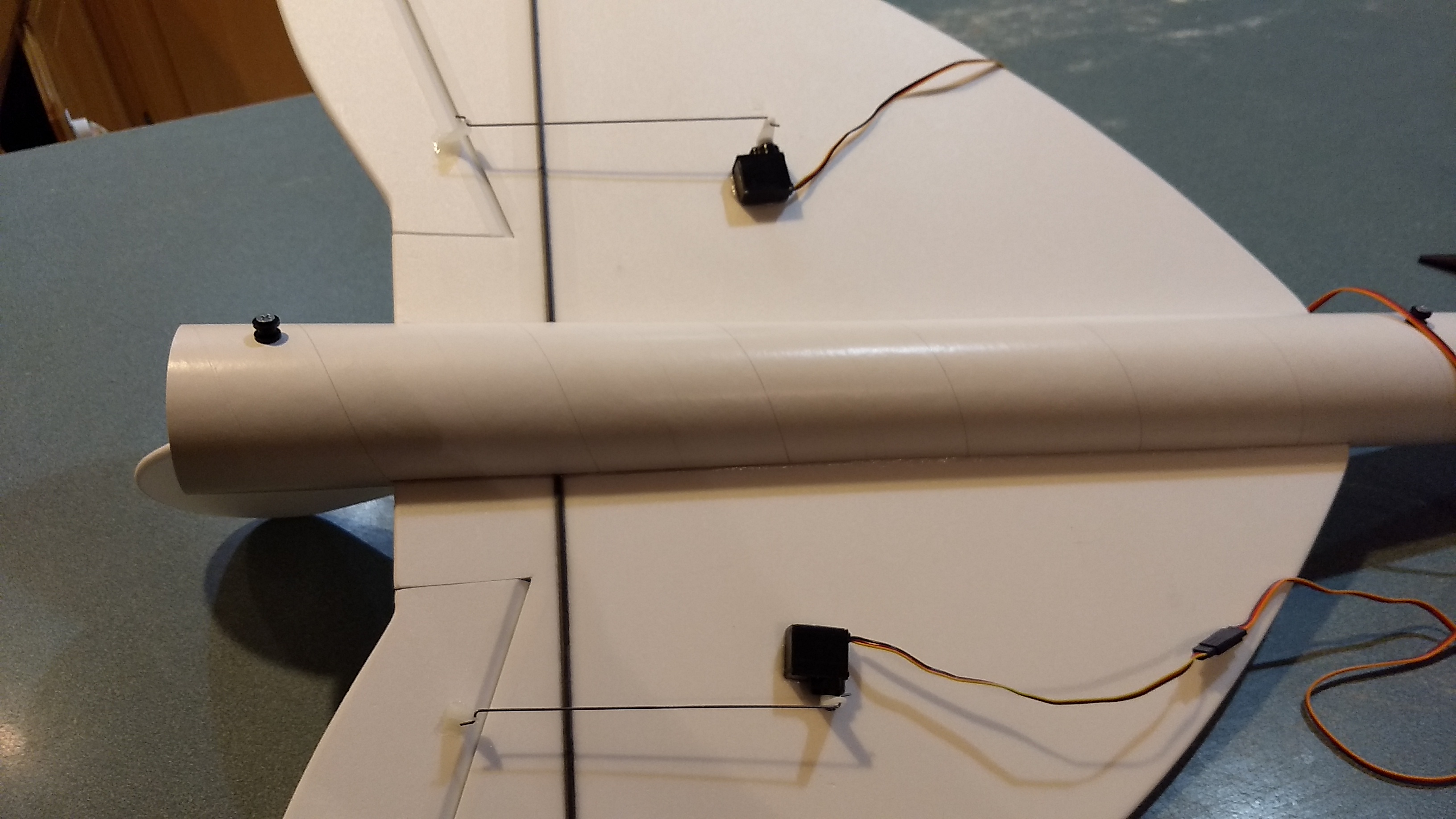
- both servos installed.
-

- Route the wire into the body tube via a slot.
-

- tape over the wire to the wing using the included blenderm tape
-

- Receiver mounted in body tube with velcro, can also be mounted in nose for CG if needed.
-
- Battery mounted in nose with velcro
-
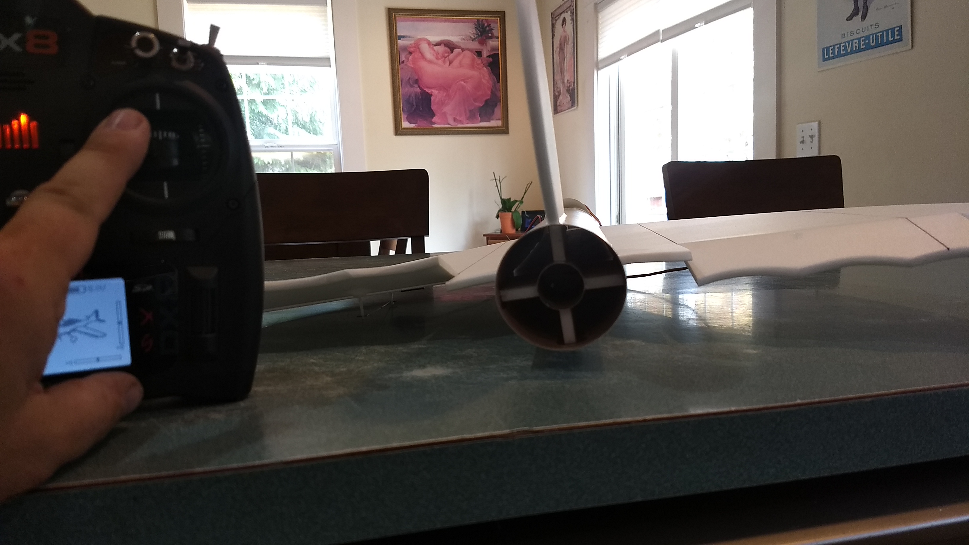
- up trim for glide
-

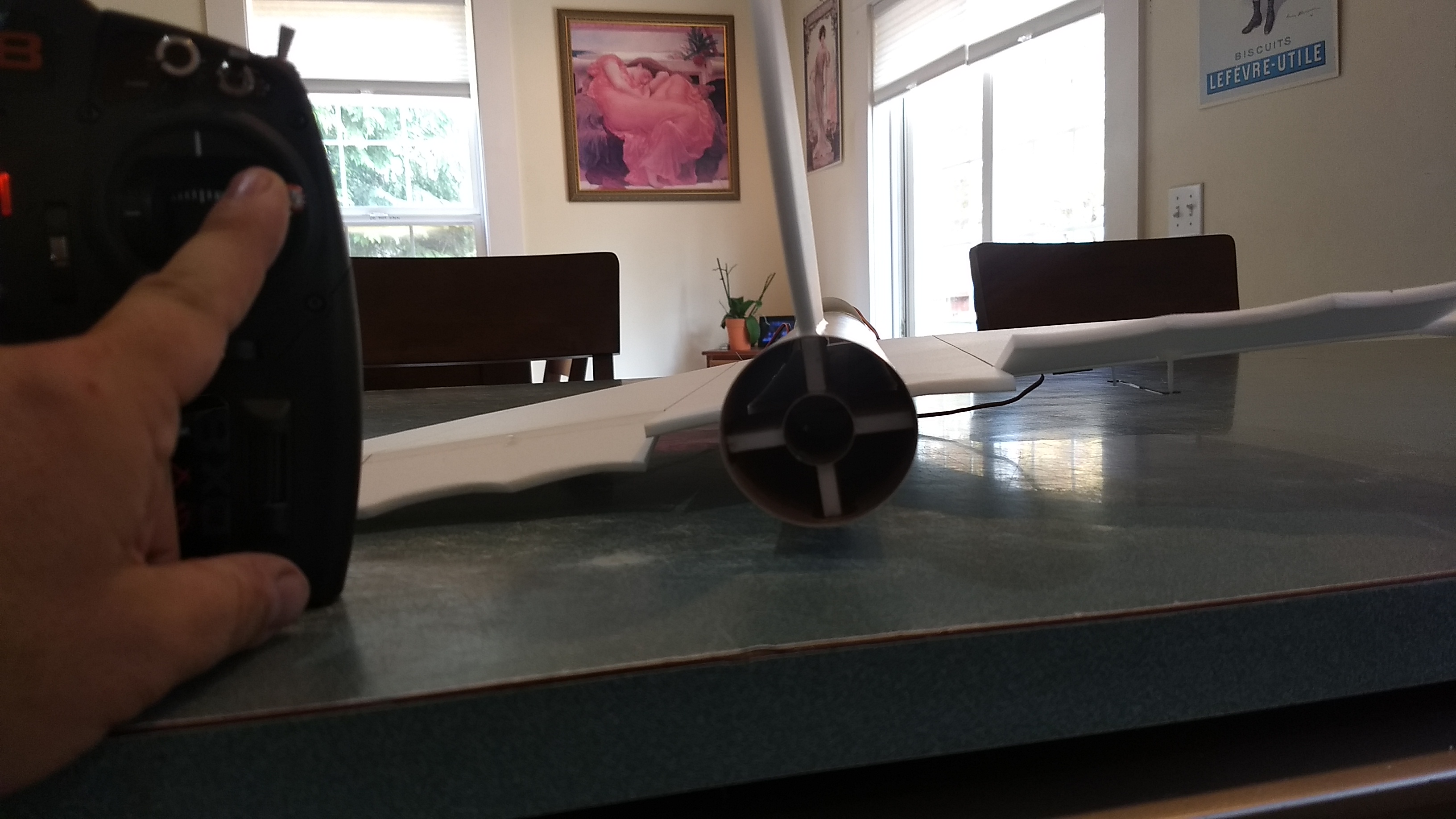
- down elevator
-
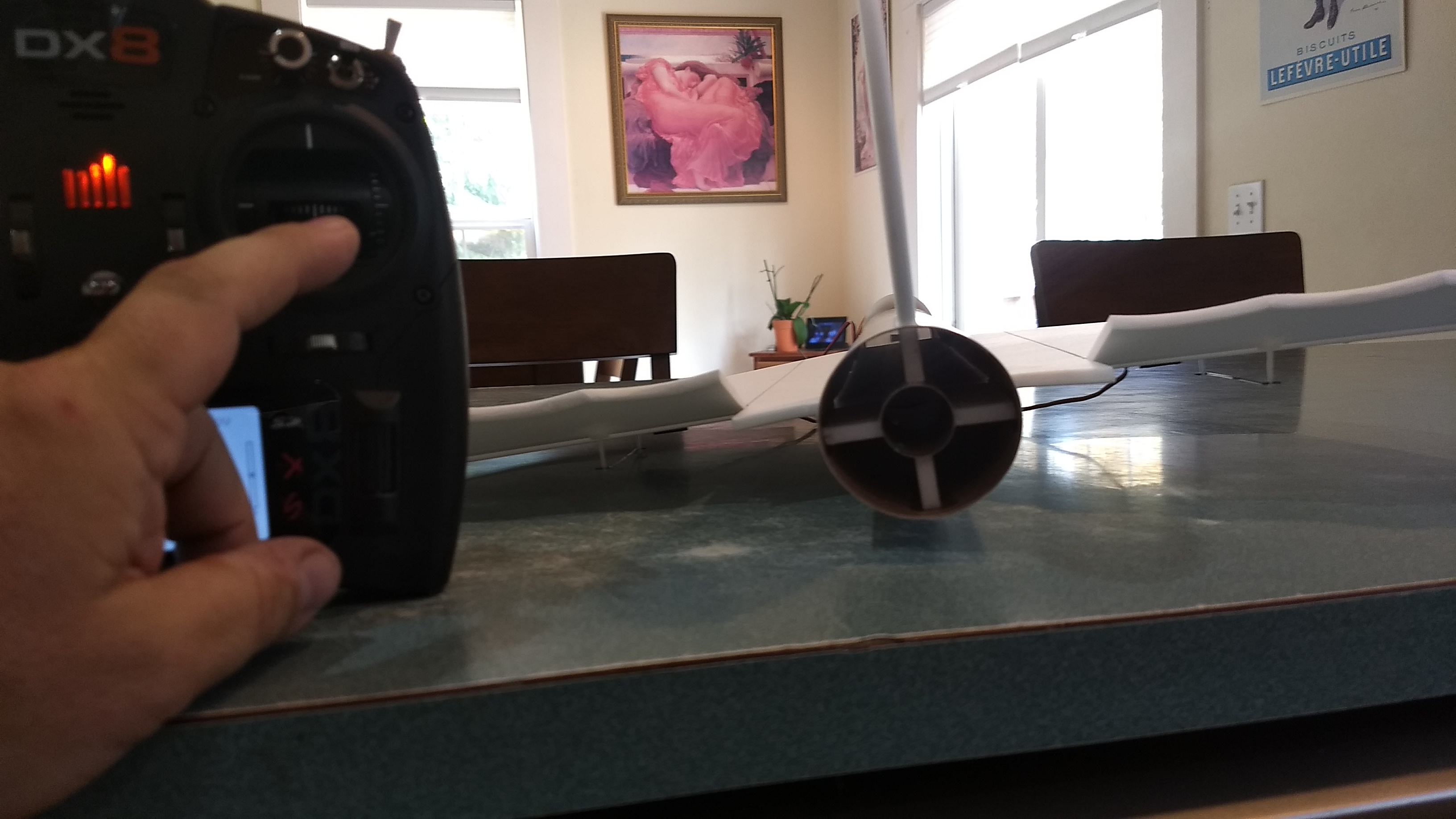
- Up elevator
-
- Right aileron
-
- left aileron
-
- Completed model
-
- Extra Machine gun detail