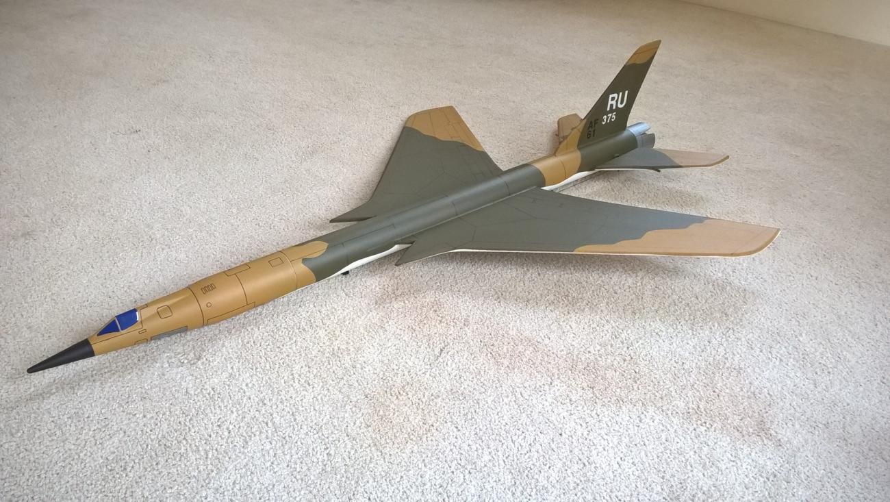
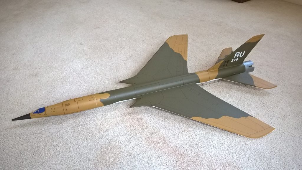
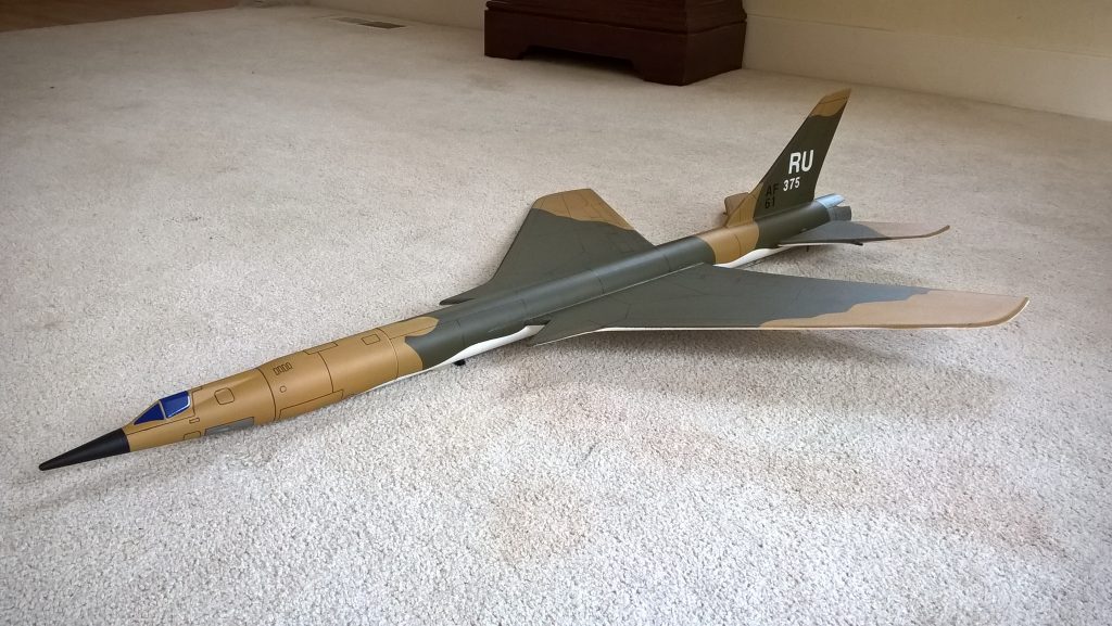
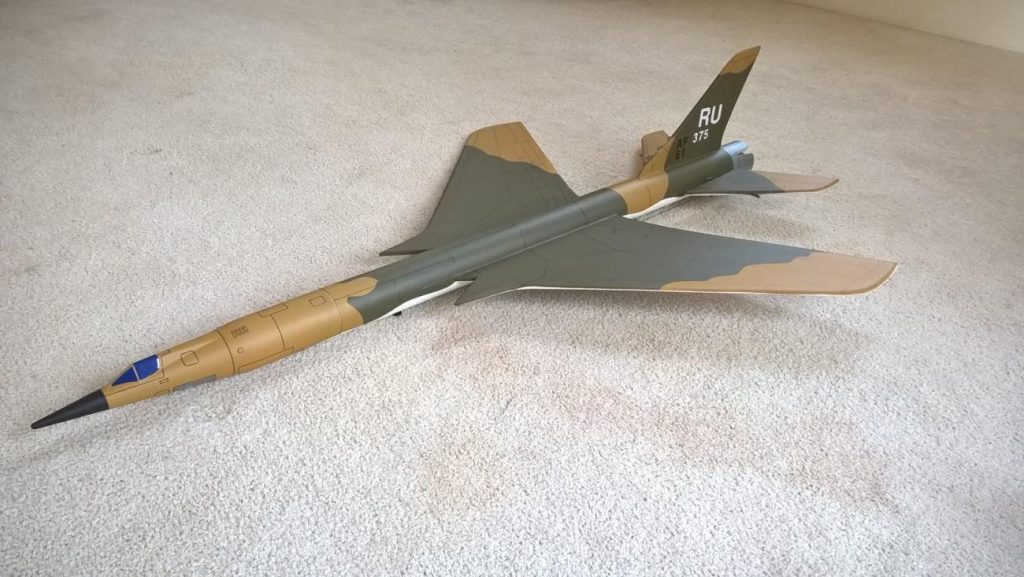
Thunderchief Rocket Glider Kit
The Thunderchief RC Rocket glider kit. This is styled after the F-105 thunderchief used in Vietnam for attack/bombing/sam supression roles. It has a light wing loading giving it a very nice glide and easy/stable boost. It comes with a plastic Interceptor nose cone, 2″ white tubing for the body and depron wing and full flying tail surfaces. Construction is slightly more complicated since you have to cut the slot in the tube for the wing after you join the two body tubes. You will need two 10 gram type servos, two 12″-18″ servo extensions, a receiver, and a small 500mah single cell lipo battery. You will need a transmitter with delta or elevon mixing. Please refer to the notes on items needed for completion and flying, then read the instructions completely before starting assembly. The assembly photos are for general reference but may not include every step in the manual.
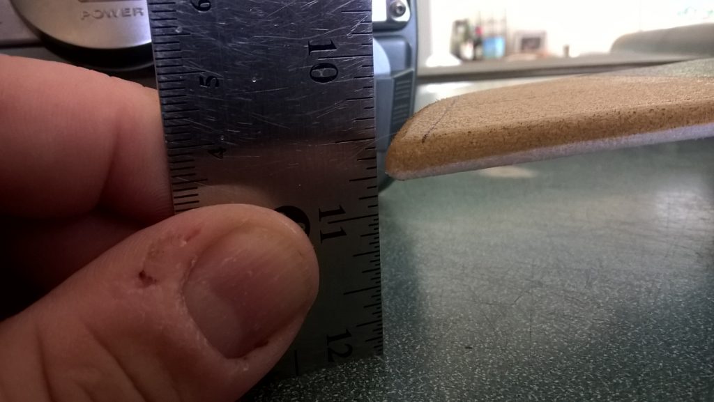
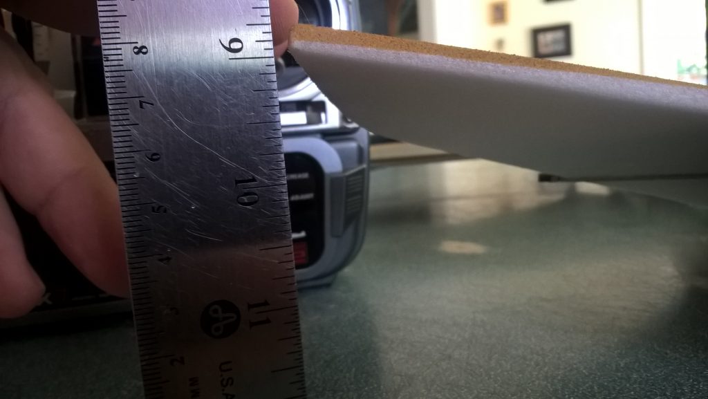
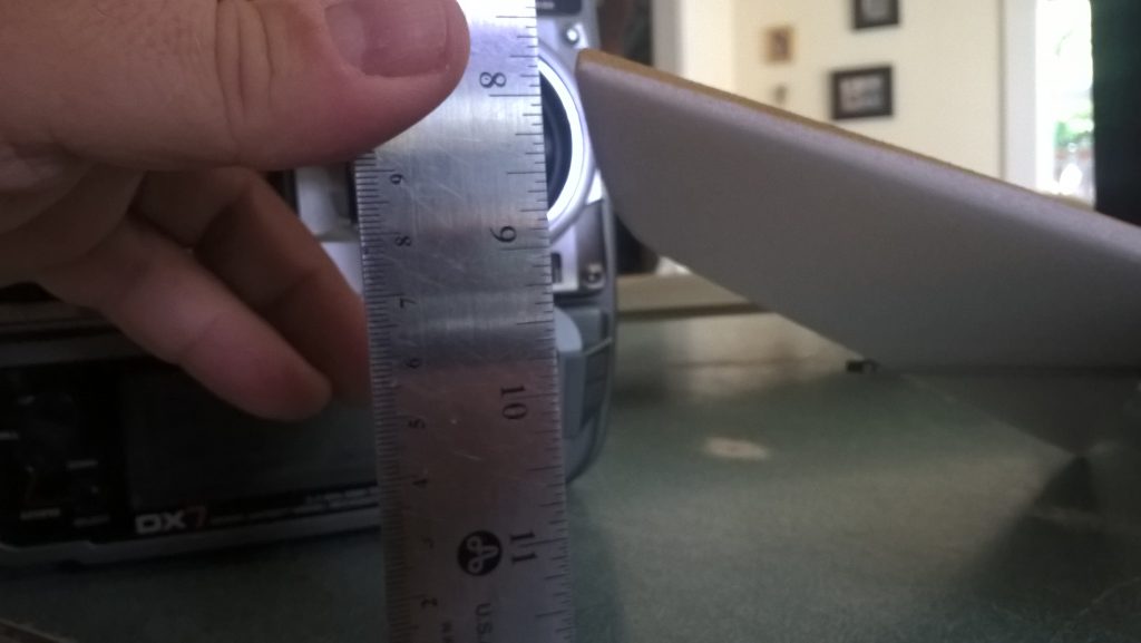
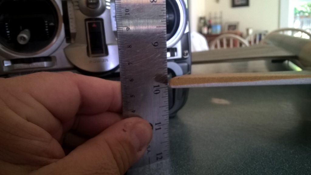
CG location for rocket flight: 15.25″ forward from the rear end of the body tube.
Welcome to the world of rocket boosted radio control gliders. This is not a model for a novice RC pilot, but anyone who is comfortable with RC flying of a medium speed model should be fine. Read through the instructions, look at the photos and be sure you understand the step before commiting to cutting or glue.
Thunderchief Rocket glider instructions
Identify all pieces, the kit should contain:
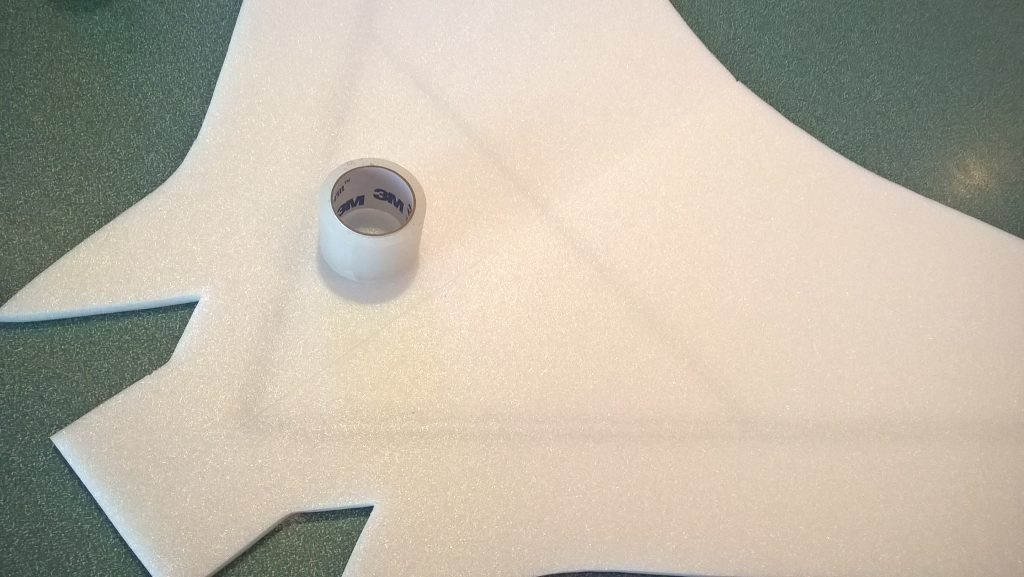
1 wing taped together
1 wing spar(carbon fiber)
2 pushrods
1 vertical stabilizer
2 horizontal stabilizers
1 tail pivot rod
1 tail pivot rataining ring
2 ez connectors
2 pushrod guides.
2 Body Tubes
Motor mount
2 centering rings
Velcro(for battery and rx/bec attachment)
2 Rail buttons with t nuts/screws or 1 Launch lug
2 landing skids
3M blenderm tape
Lead weight
Spare depron
Notes before starting:
Reference to CA+ means foam safe CA+, normal CA+ will melt the foam! Normally you need to use accelerator to get the CA to set on the foam since there is nothing for it to soak into and activate.
You may use 220-320 grit sandpaper and a sanding block to slightly round the edges of the foam if you prefer that look. It will not markedly impact the flight performance either way. Be very careful and use a light touch, it is very easy to catch the foam on the edge of the paper and tear the foam. Do any sanding before assembly.
Epoxy is not needed in this model. Weight is critical and the model is designed for the thrust and flight loads. Weight in the rear end is bad and will require additional weight in the front of the model.
Assembly:
- Glue a centering ring on the front of the motor mount about 1/8″ from the end. Make sure the notch in the ring slides over the motor hook. Glue another centering ring 1.25″ from the rear of the motor mount, again making sure the notch slides over the hook. Use a lightweight glue and use it sparingly.
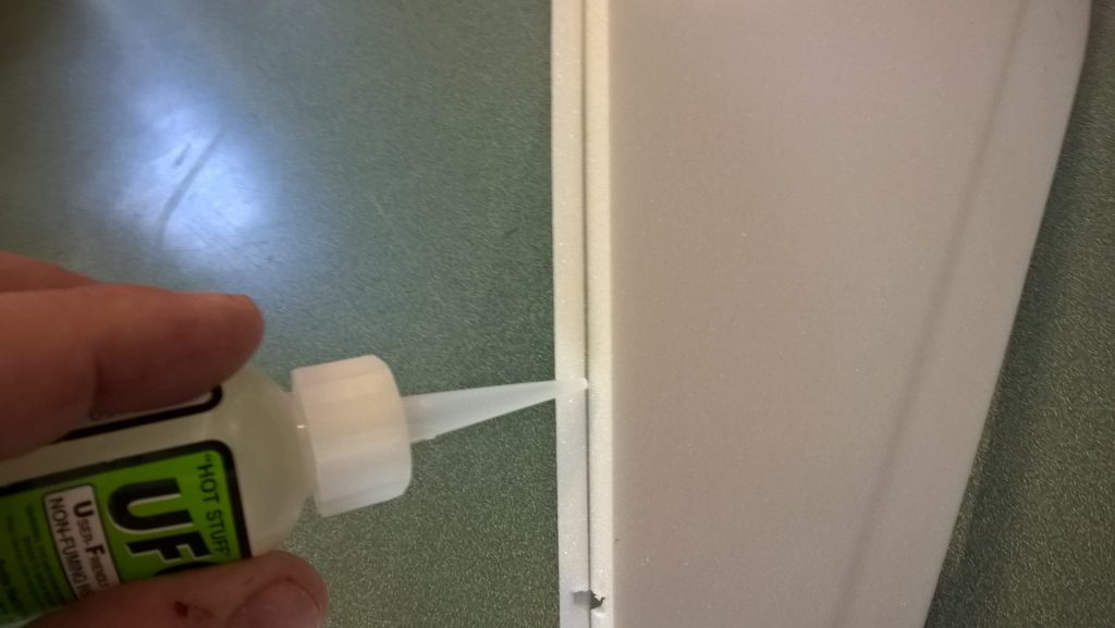
- Unfold the wing and glue it using CA+ at the taped joint, make sure it is flat. Once glued use the blenderm tape on top of the wing over the joint.
- Glue the spar into the slot in the bottom of the wing using CA+ then tape over using the blenderm tape.
- Join the two body tubes. Make sure the arrow mark on bottom of the forward tube lines up with the arrow mark on the bottom of the rear tube, this will make sure the wing cutout lines are aligned. Use glue sparingly since you have to cut through the coupler for the wing slot.
- Carefully cut out the wing slot on the lines marked. Lines are approx size. Make sure to check the wing thickness and don’t cut the slot too oversized. Take your time and go slowly. It’s easiest to do this using a piece of angle aluminum to help keep the line straight. Test fit the wing into the slot carefully. Sand or trim as needed for a good fit without dragging/damaging the foam. You’ll need to start by putting the wingtip into the slot, then rotating so that the wing goes in straight. Sand the front or back of the wing slightly if you are having trouble getting it in the slot, or trim the slot.
- Make sure the wing is centered in the body tube and glue using CA+ along the top and bottom on both sides. use CA+ and accellerator. You can squeeze the tube slightly as the glue sets to make sure it makes contact and doesn’t have a gap. Once glued in place, you can trim the forward portion of the wing flush with the body tube.
- Insert a pushrod into the third hole from the end in each control horn. The pushrod should go into the inboard side of the horn.
- Slide the pivot rod through both surfaces and the body tube, make sure the control horns are pointing down. Once installed, slide the small aluminum tube over the end of the pivot rod and CAREFULLY put a small dot of CA+ on the end of the rod and little ring and set it with accellerator to lock it in place. Be careful that you don’t get any on the moving surfaces. Make sure the surfaces are free to move.
- Install the vertical tail. Sand the slot or tab slightly if needed so that it fits. Glue in place with CA+ and add a light fillet. Make sure the fin is straight and perpendicular to the wing
- Glue in the motor mount into the tail, it should stop against the fin tab and be even or recessed slightly compared to the body tube.
- Make a hole in the bottom of the rear of the body tube at the place indicated for the rail button and install it using the T nut. Don’t tighten down really hard, just enough to secure it.
- Install the forward rail button on the mark indicated in the same manner.
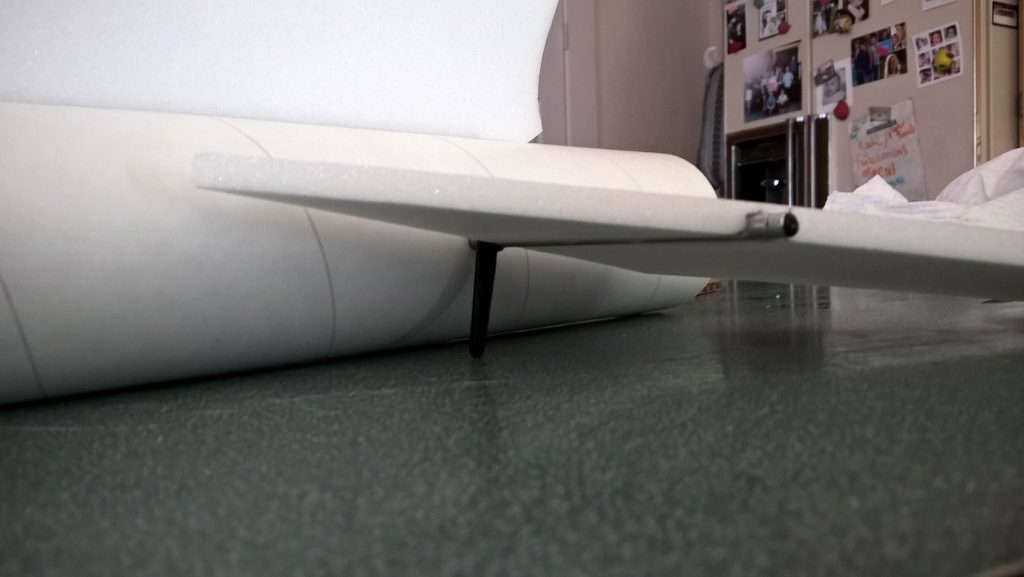
- Using a tool make two holes for the landing skid and glue one just in front of each rail button. Test fit on a rail to make sure they are aligned and don’t drag on the rail. These help protect the rail buttons from landing damage. Make sure the front skid isn’t so far forward so that it doesn’t interfere with the nose cone shoulder.
The basic construction is now complete.
Radio Installation
Note: Your radio needs to be configured for Delta mixing, this means that the servo arms will move the same direction during elevator stick movement and opposite for aileron stick movement. Connect your servos to the receiver one in the aileron connection and one on the elevator connection and apply power. Use a servo arm at least 9/16” long and with holes small enough that there won’t be slop with the pushrod wire when installed. I use the hole furthest out on the servo arm, to maximize movement. On some servos there are a long two-ended servo arm, you can trim off one end if needed to get sufficient length. Zero out any trim settings on the transmitter. The model once the motor has burned out is nose heavy and flying wings lose pitch authority when nose heavy so you want as much up elevator travel for trim/flare as possible.
- Install an EZ connector onto each servo output arm. Slide one of the standoffs onto each control rod using the outermost hole. They will be glued in place later. Connect a servo to each pushrod, the servo control wire should be pointing forward and the servo arms should be facing the body tube so that the pushrod makes a straight shot to the control horn. Once connected, tape each servo in place on the underside of the wing just to the rear of the CG so that they are not on the blenderm tape. Flip the model right side up and look at it from the rear. Moving the transmitter stick back(up elevator) should move both elevons up. Moving the transmitter stick to the right should move the right elevon up and the left elevon down. If you can’t get the servo reversing to give you the right polarity try swapping aileron/elevator inputs to the receiver or turning the servos over and swapping the servo arms to the other side of the output shaft. If that is correct, continue.
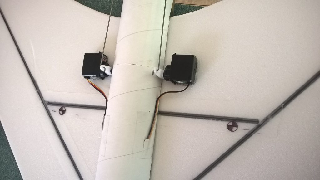
- Flip the model upside down and supported. The servos may be attached to the model using double back servo mounting tape(not included) or by directly gluing the servo to the wing with CA+ or a small amount of epoxy. Double back servo tape can loosen over time and with exposure to heat, I prefer to glue the servo in place. With the radio still on, put a small amount of glue on the servo, being careful not to get any near the output shaft. And set it in place on the model keeping the control surface centered. Do the same to the other side. Make sure the glue is set before continuing.
- Flip the model back right side up. Make sure the control surfaces are centered, use trims if needed or adjust with the ez connectors. Now measure the control surface movement. Full elevator movement should be 2 in each direction, aileron movement should be 3″ in either direction. Since the model will be nose heavy, extra elevon movement helps to give sufficient authority during glide.
- If you have a flap/elevator mix you can program up elevator to a switch setting. The model needs approximately 3/4″ of up elevon during glide and may need some down/roll trim for boost depending on how you built your model. If you can’t set the up elevator trim to a switch on your radio you’ll have to manually put in boost and glide trim which is hard to do while flying the model.
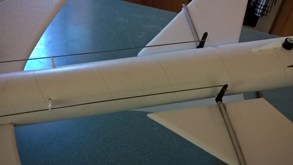
- Once the servos are attached and throws are set, attach the standoffs on the model to support the pushrod. You will make a slot in the body tube and push the standoff into the tube and CA it in place. You want the standoff about midway between the servo and control surface and be aligned so that it doesn’t drag on the rod, but just provides support to the rod so that air loads wont’ cause the rod to bend/flex. Refer to the pictures.
- Attach a 12-18″ servo extension to each servo.You just need to be able to route the wire to the front of the tube to attach it to the receiver.
- Make a slot on each side of the fuselage 2″ ahead of the coupler joint and pass the wires through to the inside and toward the front.
- Attach the servo wires to the receiver and make sure they are going the right direction. Tape down the servo wires and tape over the slot in the body tube.
- Use the included Velcro to attach the receiver 2″ from the front of the body tube on the top(or enough to allow the wires to clear the shoulder of the nose cone). This allows you to be able to remove and replace the receiver if needed for repairs or for removing the servo wires. I attached the battery inside nose cone on the shoulder.
- Insert your heaviest loaded rocket motor into the motor mount
- Support the model upside down at the balance point indicated for boost. I use two pencils with the eraser pointed up and held in place with a small hand vice. Place the model upside down on the pencil erasers on the balance point indicated in the kit spec sheet. Use the included lead weight to balance it either in the nose or tail as needed. Do not try to fly the model with it balancing it behind this point. The adage is, a nose heavy model flies poorly, a tail heavy model flies once
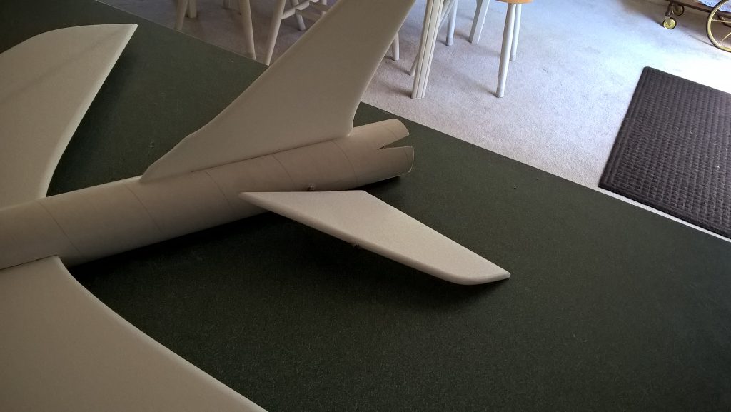
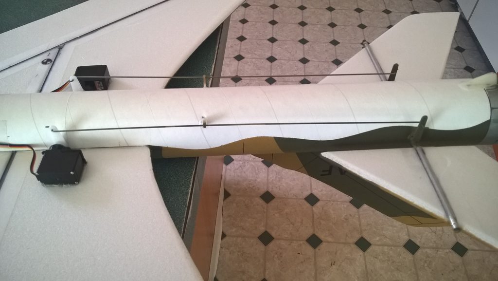
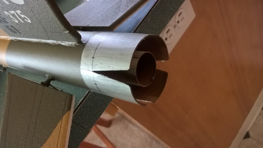
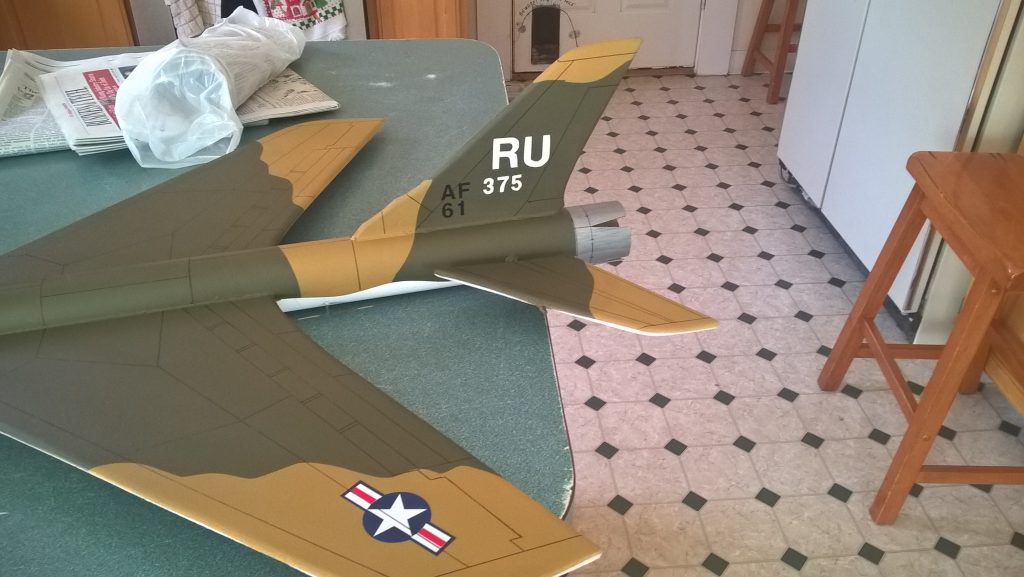
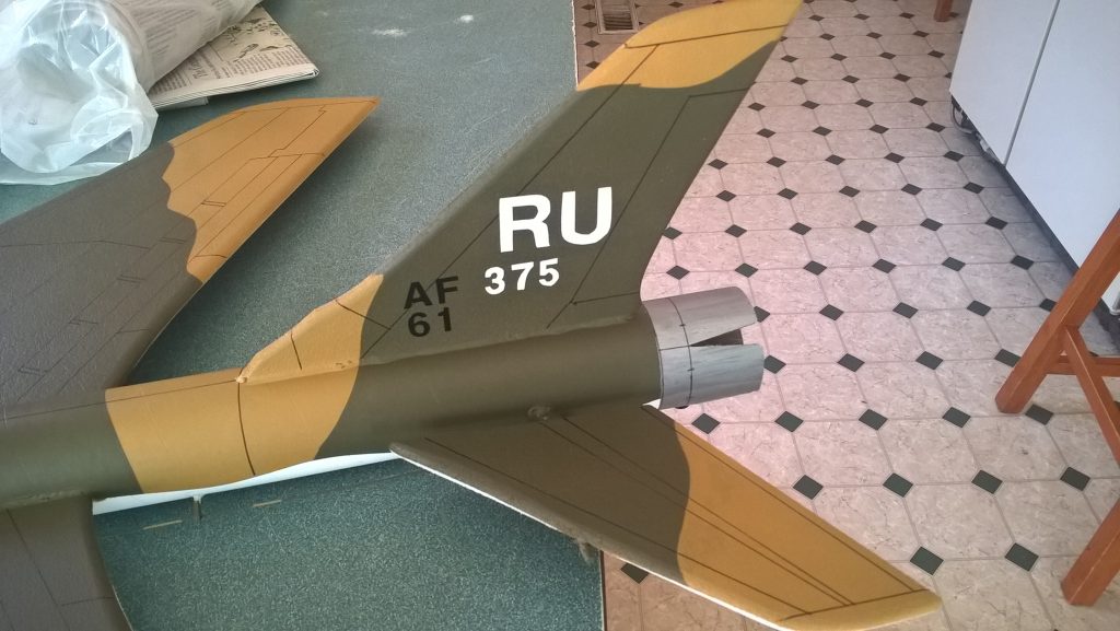
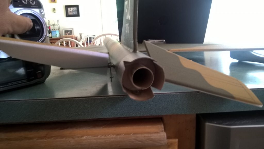
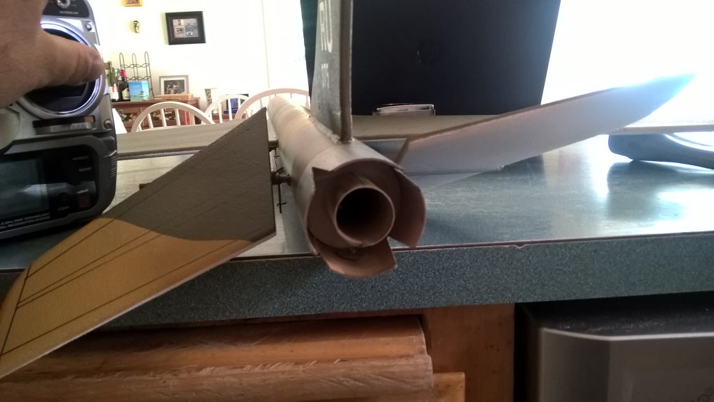
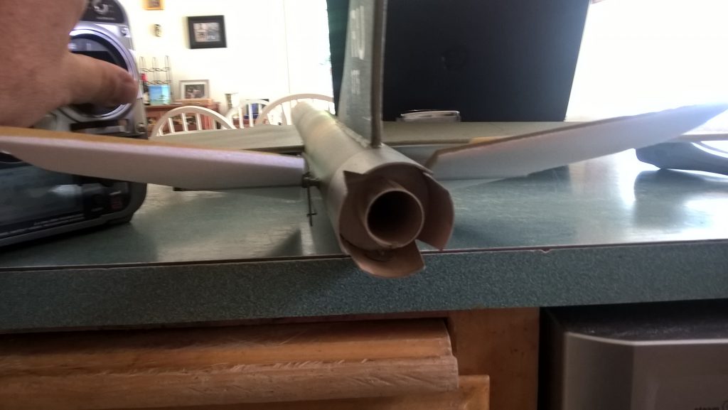
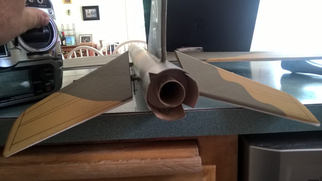
- I also cut some “V” notches in the rear of the body tube and painted them silver to mimick the afterburner/speed brake petals on the real aircraft as if they were partially deployed. You could also put some triangular black paint or vinyl to simulate the same thing.
- If you paint the model, make sure you test it on scrap foam first.
- If you are going to paint the model, you can mask off the servos. Make sure no paint will get on the servo output arm. Make sure to test the paint on a scrap piece first to ensure it won’t melt the foam. I use Model Master(testors) or testors small rattle cans for painting directly on the foam.
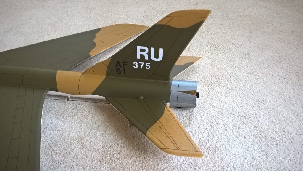
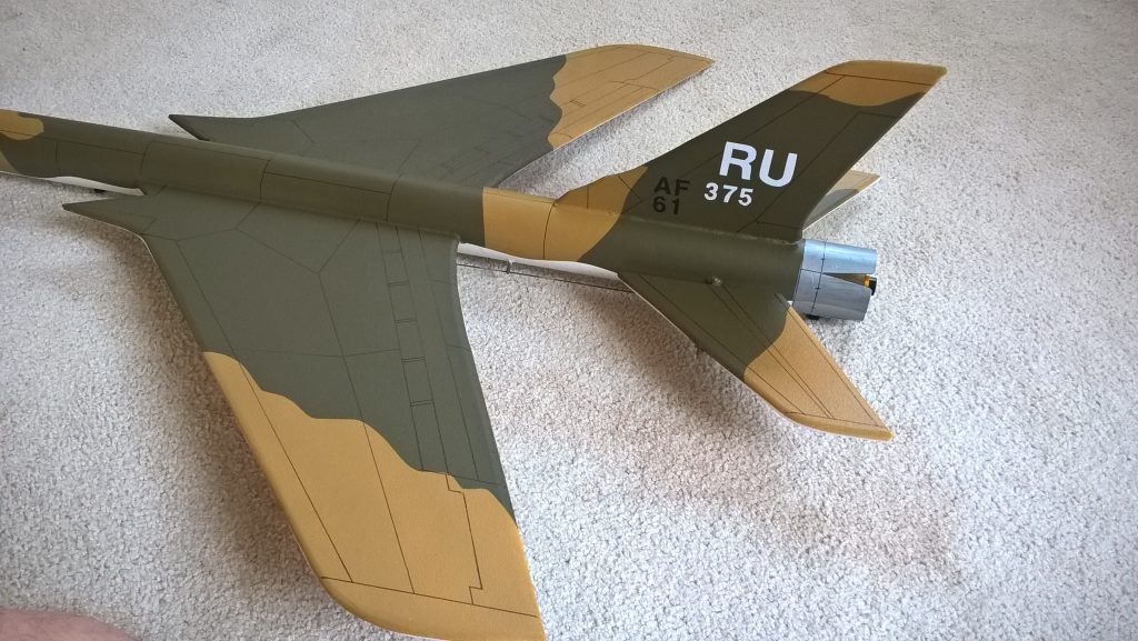
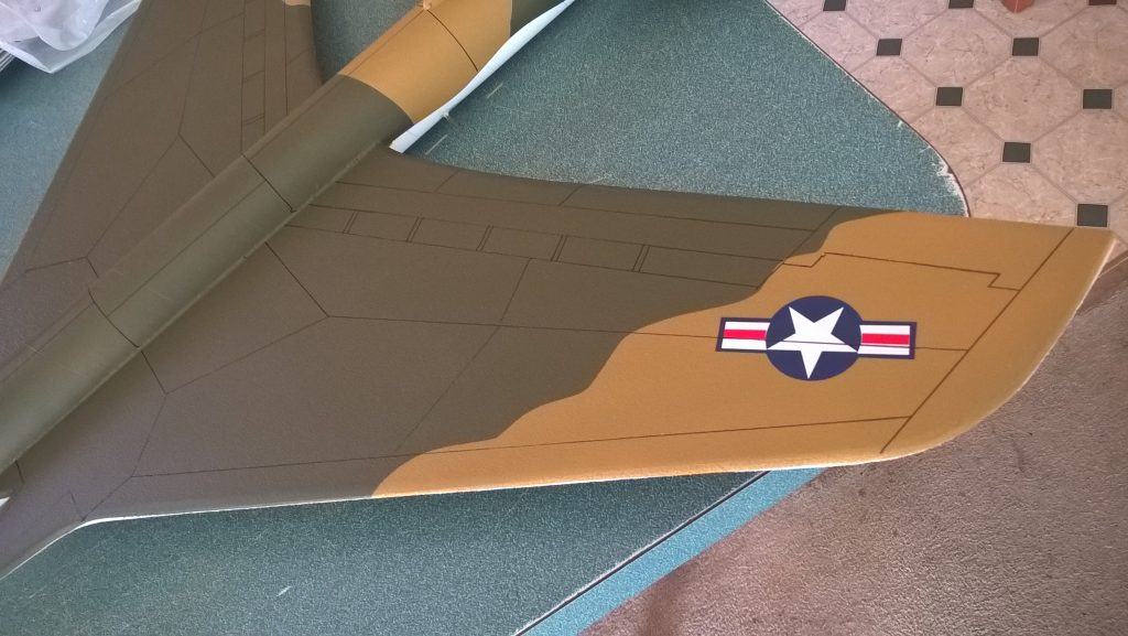
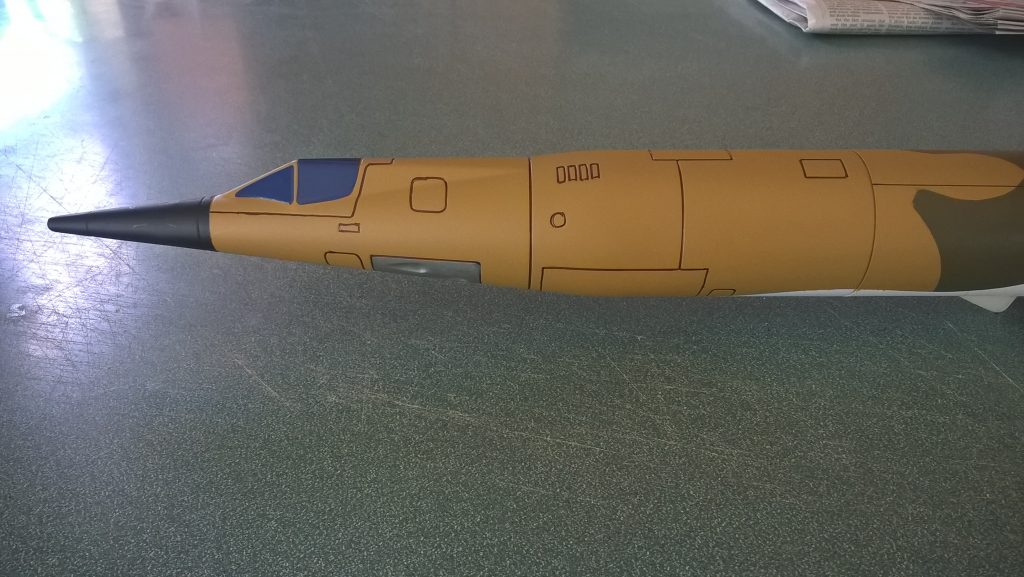
- I masked off the bottom of the model to keep it white, then I used model master africa mustard for the base color. I then masked off the camo pattern and sprayed the testors OD green on top. Paint added approx 1/2 ounces to the overall weight.
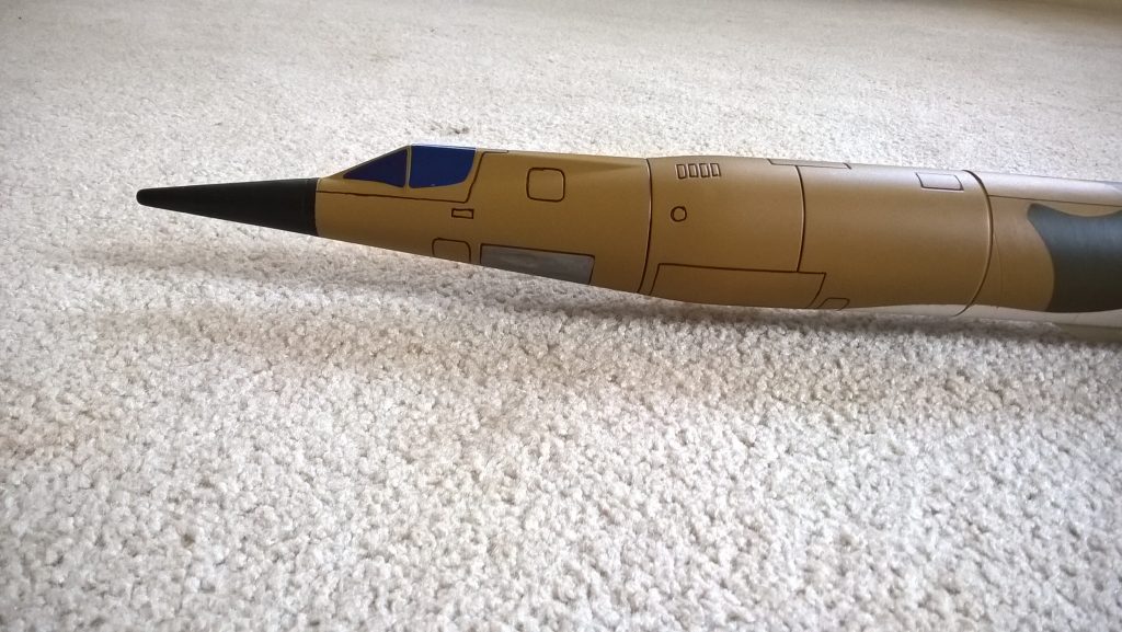
- Use a black sharpie to add panel lines if desired, I ran a fine line sharpie into all the panel lines in the nose cone and it really sets it off.
- I used vinyl trim for the canopy and tail markings, it helps to use a hot hair dryer to heat the decals and then push them down into the paint to make sure they adhere well.
- Re-install the receiver and battery
Flying: See the Instruction/Information link at the top for flying instructions Note, my prototype needed a small amount of down trim on boost and as it gained speed arced back up vertical. Be ready on the first few flights to keep the model straight till you have the trims set perfectly for boost and glide.
-
- Join body tubes so arrow marks align, then cut wing slot, then glue wing joint
-
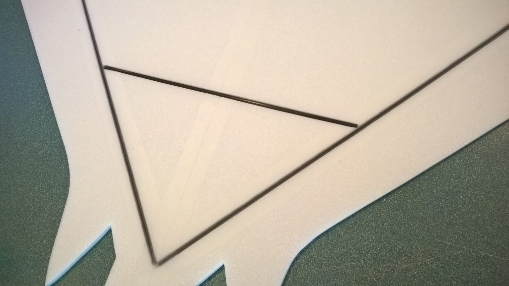
- Install Spars, then tape over spars and center joint
-
- Flip the wing over
-
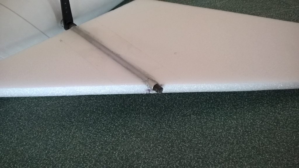
- Put pushrods into horns in the third hole from the end, then Install pivot rod and stabilizers
-
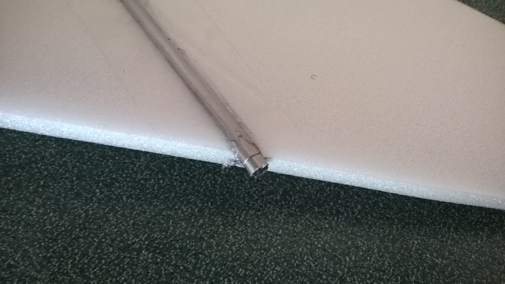
- Cap stabilizers with aluminum cap
-
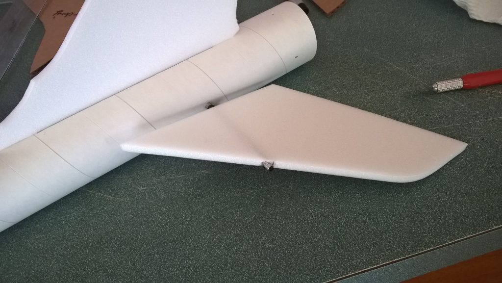
- Stabilizers installed
-
- flip model over
-
- Install Vertical stab
-
- Install wing and glue when centered
-
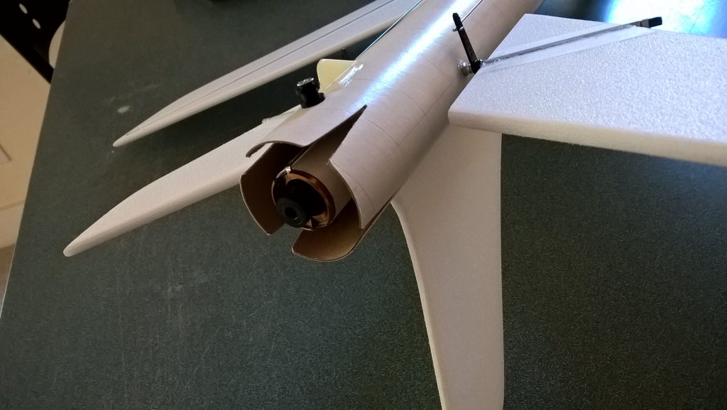
- Install Rail buttons, and skids, install centering rings onto motor tube, then glue in motor tube
-
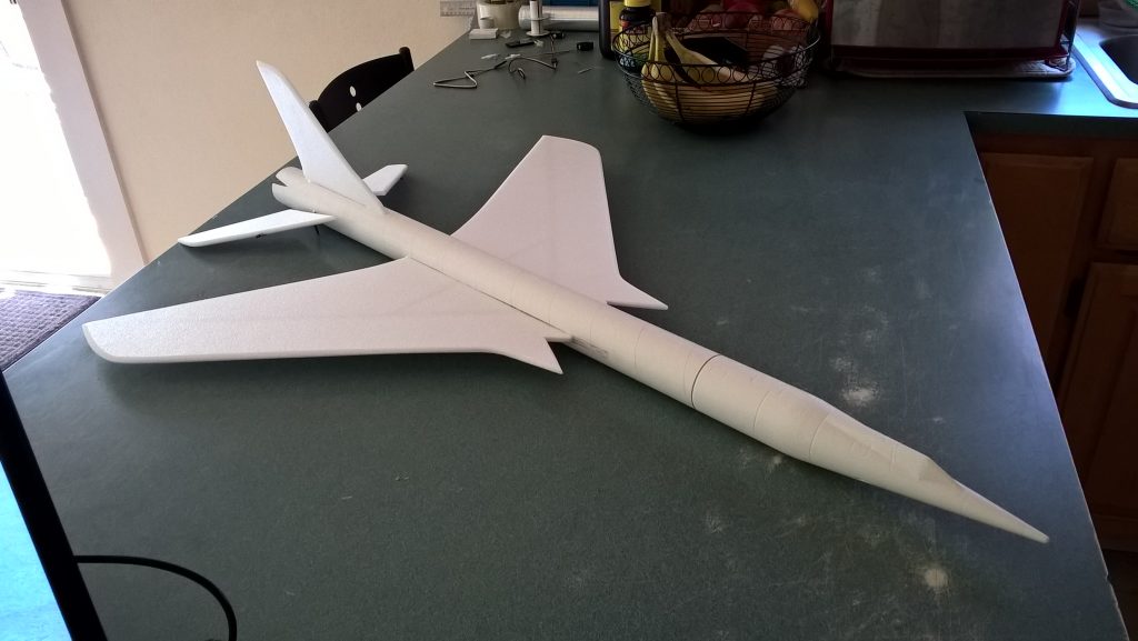
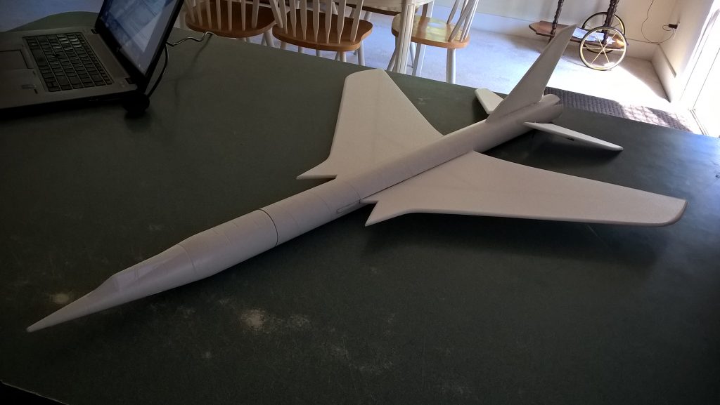
- Completed airframe
-
- Install supports for pushrods onto rods but glue in place after servos are installed making sure the pushrods ar estraight and supported.
-
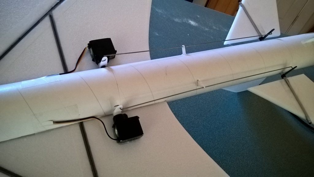
- Install servos, then glue supports in place
-
- Route servo wires into fuse and tape over
-
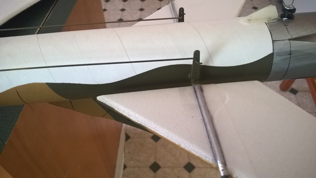
- Closeup of pushrods
-
- left aileron
-
- right aileron
-
- Up elevator
-
- Down elevator