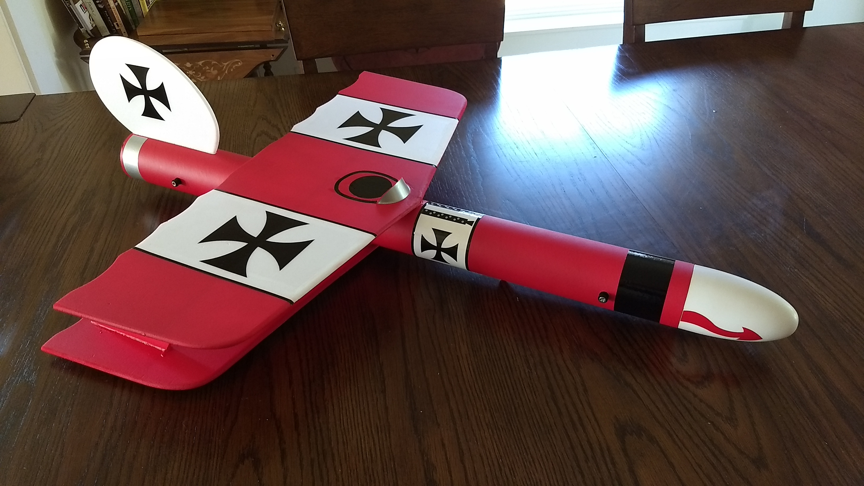
The Das RokitStik RC Rocket glider kit is a fantasy rocket powered biplane themed after the classic Radio controlled Das Ugly Stik series of planes originally designed by Phil Kraft in 1966. It comes with a plastic nose cone, 2.6″ white tubing for the body, Depron wing and 6mm depron tail surface. Spars are pre-installed and no slotting of the body is required. Please refer to the General information for all kits tab above, then read these instructions completely before starting assembly. CG location for rocket flight: 14″ forward of the rear end of the body tube, balanced by placing the balancing rods under the top wing with the model upright and having a slight nose down attitude.
Decals available from Stickershock23.com
Welcome to the world of rocket boosted radio control gliders. This is not a model for a novice RC pilot, but anyone who is comfortable with RC flying of a medium speed model should be fine. Read through the instructions, look at the photos and be sure you understand the step before committing to cutting or glue.
Identify all pieces, the kit should contain:
2 wings
1 Nose Cone
1 vertical stabilizer
4 wing reinforcing strips
2 Interplane Struts
2 control horns/Pushrods
2 Body Tubes
Motor mount
3 13/16″ x 2.5″ wide strips to center the motor tube
Velcro(for battery and rx/bec attachment)
2 Rail buttons with t nuts/screws
Lead weight
Notes before starting:
Foam safe CA+(Bob smith super gold + is good) is the only glue recommended for construction. You will also need foam safe accellerator to set the glue.
You may use 220-320 grit sandpaper and a sanding block to slightly round the edges of the foam if you prefer before gluing the wing and vertical stab in place. Do any sanding before assembly.
Assembly:
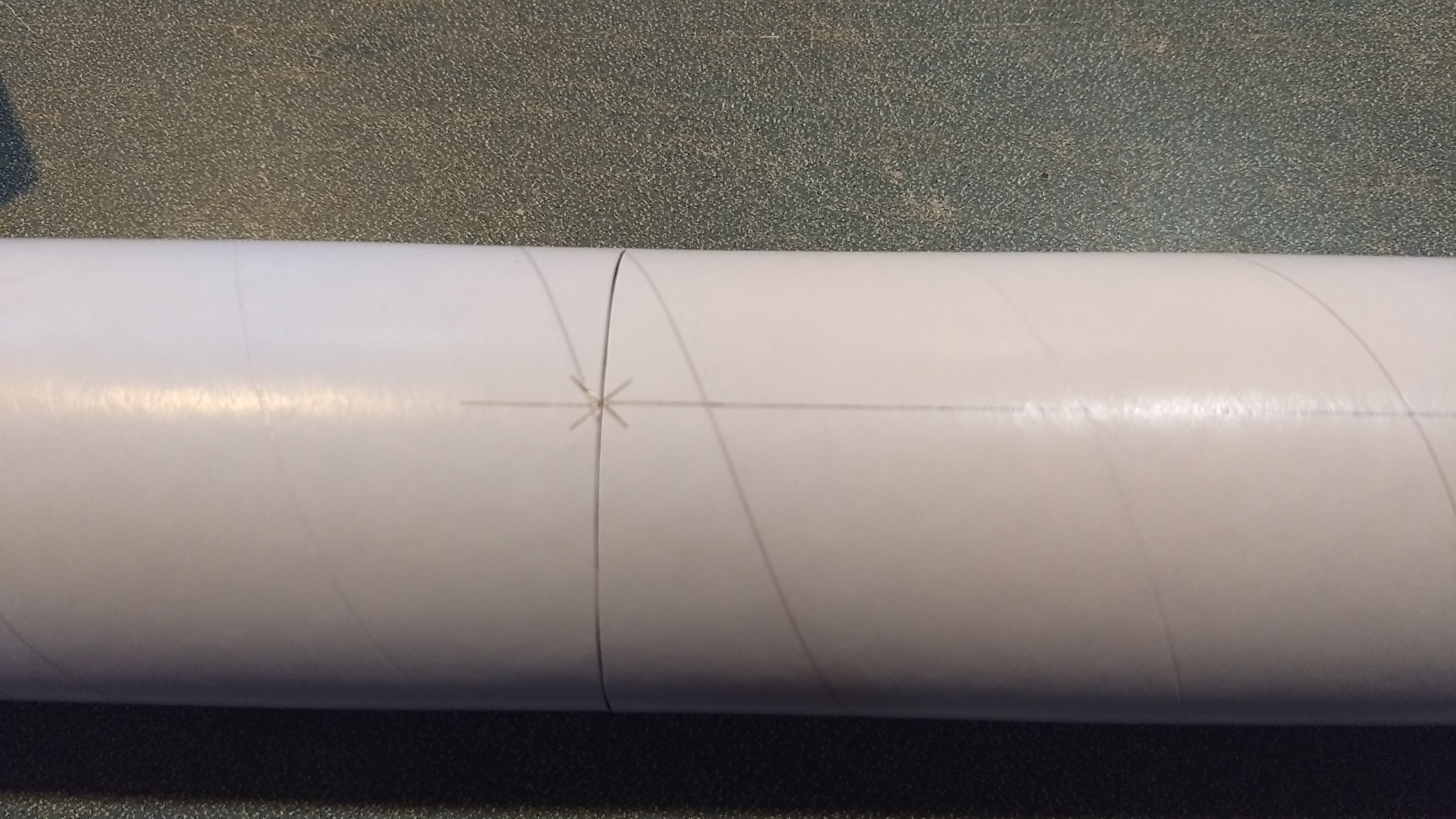
- Body Tubes. One tube will have a coupler pre-glued in place. Glue the other tube onto the coupler, make sure the small arrow marks are aligned on the two tubes, that will ensure wing line and rail button marks are properly aligned.
- Using an X-Acto, cut out the hole in the rear and front rail button locations marked on the bottom of the tubes to fit the t nuts. Insert the T nuts from the inside of the tube and install the T nuts, rail buttons and screws, don’t tighten them down really hard, just snug enough to not come out. The rail buttons are in the right locations so that they do not interfere with the vertical fin or nose cone shoulder and so that the rail will not rub on the servo or control arm during launch. It may be helpful to set the t nut on a ruler, and insert it into the body tube, then press into the hole from the inside then start the screw and rail button pieces. It may be helpful to have someone hold the tube for you. Photos show this step after the vertical fin is installed, but it is easier to do it now.
- Lightly sand the body tube on the bottom wing line pencil mark to help glue adhesion.
- the lower wing has the hinged control surfaces installed. The bottom of the wing has the spar visible.
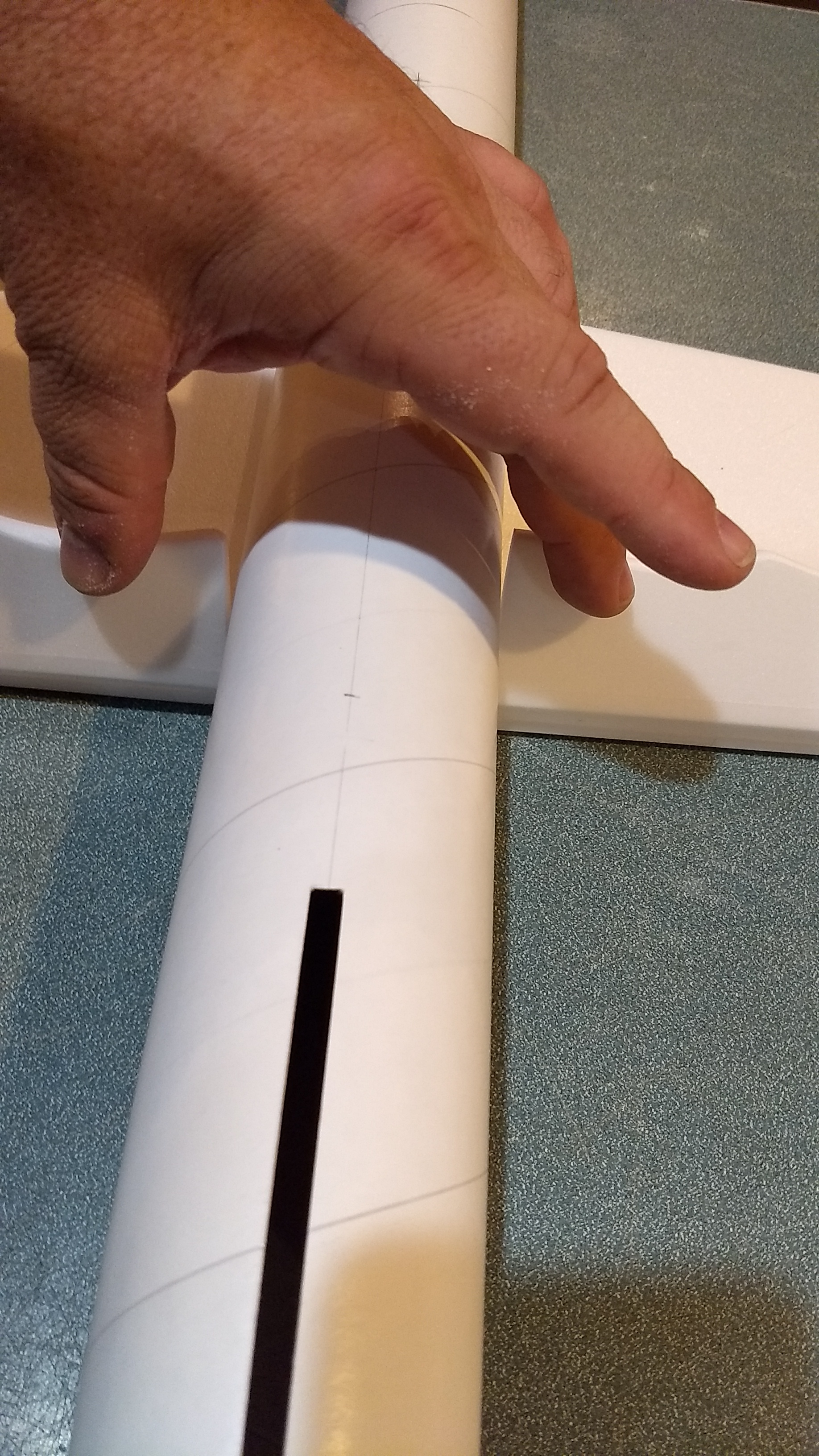
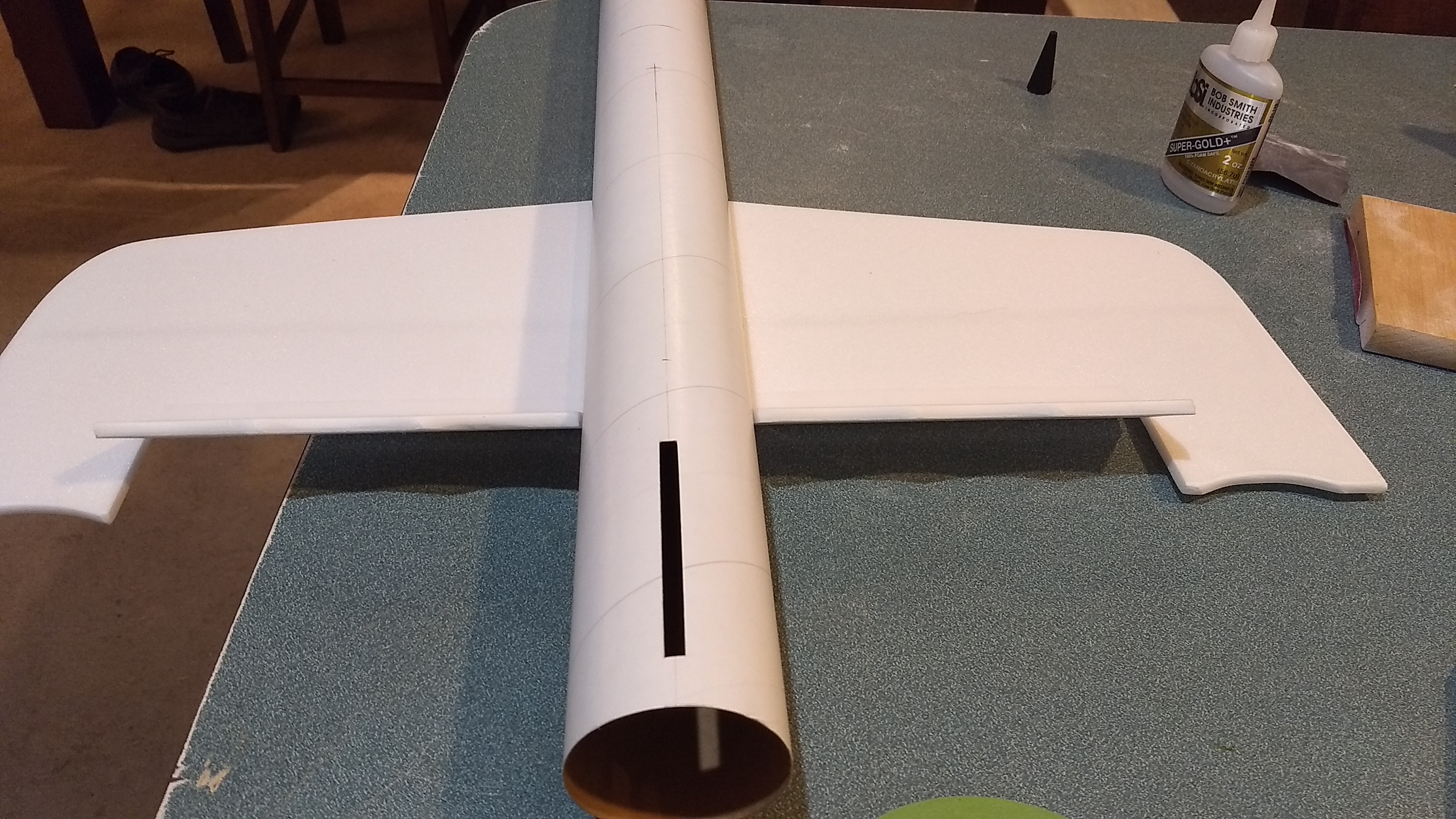
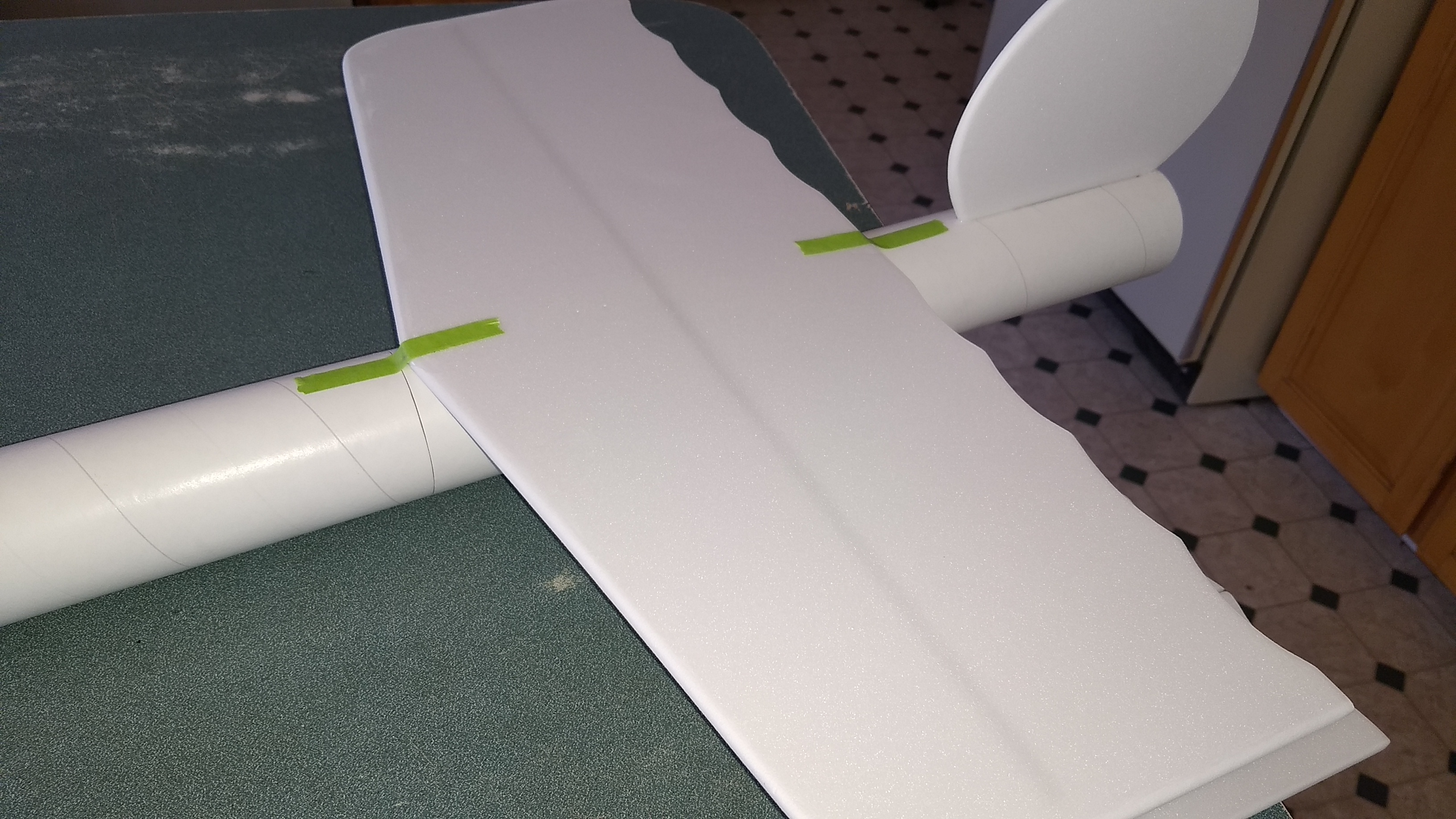
- Apply CA to the fuse and top center of the wing and lay the wing over the body tube upside down, and make sure the rear of the wing is even with the pencil mark on the body tube and the front is aligned with the other pencil mark, and the front and rear index marks are aligned with the longitudinal line on the body tube. Apply tape to hold it in place then set it right side up and make sure the body tube slot at the rear is vertical. If you fold the elevons up they can help you center the wing, the elevons should not drag on the body tube and be evenly spaced. It helps to put the horizontal tail under the front of the body tube to help it sit flat on the wing. Hold in place till the glue is set.
- Once set apply glue to a reinforcing strip on the flat bottom and the sharp angle edges and slide it into the joint between the body tube and the wing. This adds extra glue surface to help reinforce the wing joint. The foam strip should be centered front and back on the wing. Apply a fillet on the top and bottom of the strip/wing and strip/body tube joint. Repeat on the other side. BE CAREFUL to NOT PUSH THIS IN TOO HARD or it will roll the tube to the side and it won’t be centered any more. Just lightly place it. Repeat on the other side, then put a fillet of CA against the wing and tube where the reinforcing strip touches them.
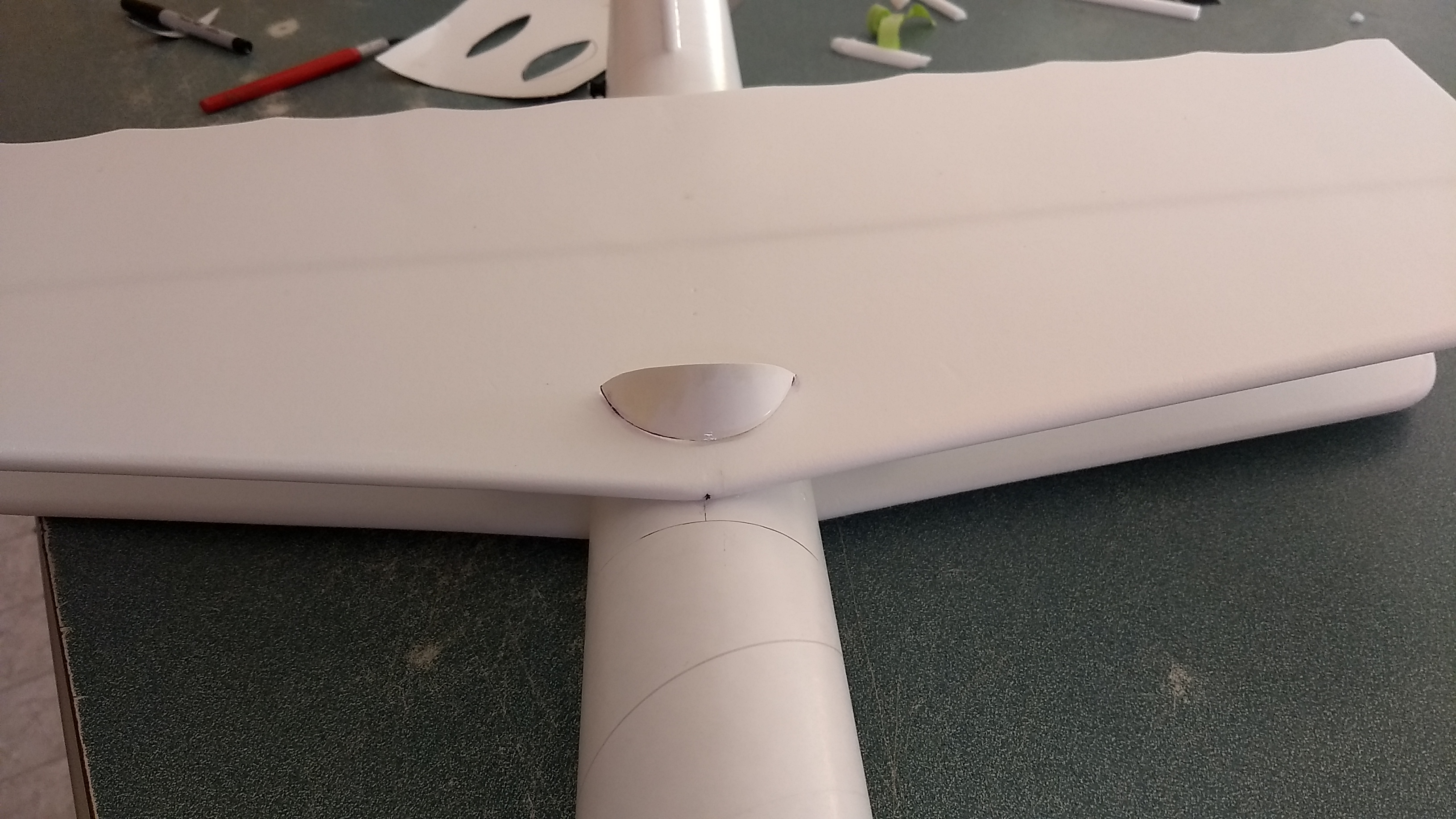
- Glue the vertical fin into place and make sure the vertical fin is straight up and down using a triangle or something similar. Apply a light filet to both sides of the vertical stab on the inside and outside of the body tube.
- Glue three 2.5″ long foam strips on the motor tube using foam safe CA+. These help center the motor tube in the body tube once you insert it into the body tube. Make sure the motor hook is about 45 degrees offset from these tabs so that hook has clearance to move. Make sure not to glue to the motor hook. Note the tabs will be on the sides and bottom of the tube, the fin tab will make contact on the top of the tube. Refer to the picture.
- Test fit the motor mount into the body tube and under the fin tab. Make sure it fits, or sand the foam tabs lightly. Glue the motor tube in place, it will inset about 1/2″ from the end of the body tube. Put a fillet on each side of the motor mount tabs and fuselage, NOTE*** the motor hook is glued at the front, make sure you have the front forward when you glue it in place. Make sure the vertical stab stays vertical.
- Note that there should be two holes on each control surface, these should be approx 2″ from the inboard end of the control surface so that the control horn faces forward and the holes where the pushrod go through are aligned with the hinge line. Apply CA+ to each of the control horns and press them in place in the TOP of each control surface into the pre-made holes. The control horn holes face forward and the pushrod should be closest to the body tube. Apply a fillet around the control horn on the the prongs on the bottom of the wing to lock them in place.
At this point you will install the servos before you put the top wing in place.
Radio Installation
Note: Your radio needs to be configured for Delta mixing, this means that the servo arms will move the same direction during elevator stick movement and opposite for aileron stick movement. Connect your servos to the receiver one in the aileron connection and one on the elevator connection and apply power. Use a servo arm at least 9/16” long and with holes small enough that there won’t be slop with the pushrod wire when installed. I use the hole furthest out on the servo arm, to maximize movement. On some servos there are a long two-ended servo arm, you can trim off one end and use that arm to get sufficient length. Zero out any trim settings on the transmitter.
- Connect each servo to a pushrod. If the pushrod is too tight, you can use twist an X-Acto knife in the servo arm hole to make it larger, but be careful and do not make it too large. The servo should be next to the body tube on the top of the wing, with the servo electrical wire pointing forward and the servo arm pointing toward the wing tip. Hold each servo in place so that the control surfaces are centered. With the model right side up look at it from the rear. Moving the transmitter stick back(up elevator) should move both elevons up. Moving the transmitter stick to the right should move the right elevon up and the left elevon down. If you can’t get the servo reversing to give you the right polarity try swapping aileron/elevator inputs to the receiver or turning the servos over and swapping the servo arms to the other side of the output shaft. If that is correct, continue.
- The pushrods should naturally align to the servo. The z bends are made using a tool but it doesn’t always align perfectly. You can use a needle nose pliers to adjust the z bend to allow the servo to sit right next to the body tube without having to put strain on the pushrod. The ends of the z bends are left angled out at a slight angle so that it is easier to insert and remove the servos from the wire if needed.
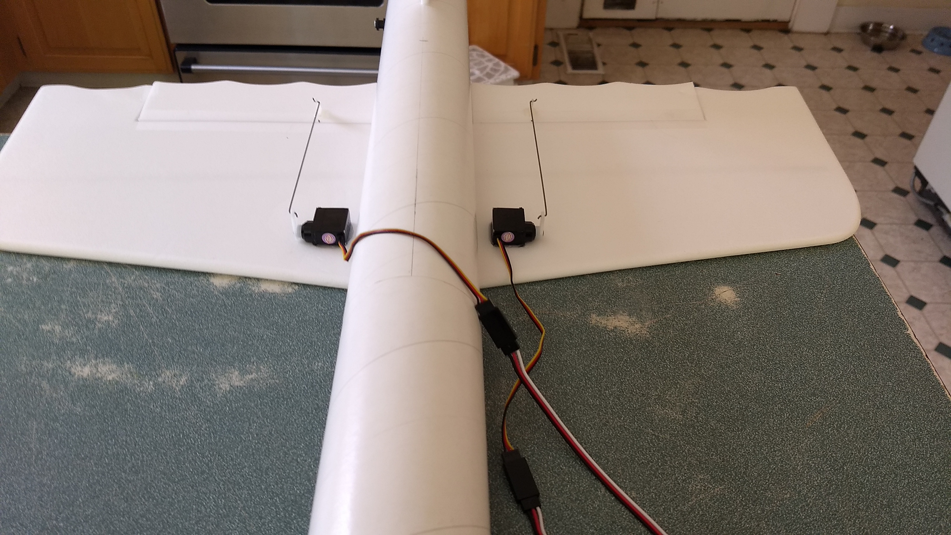
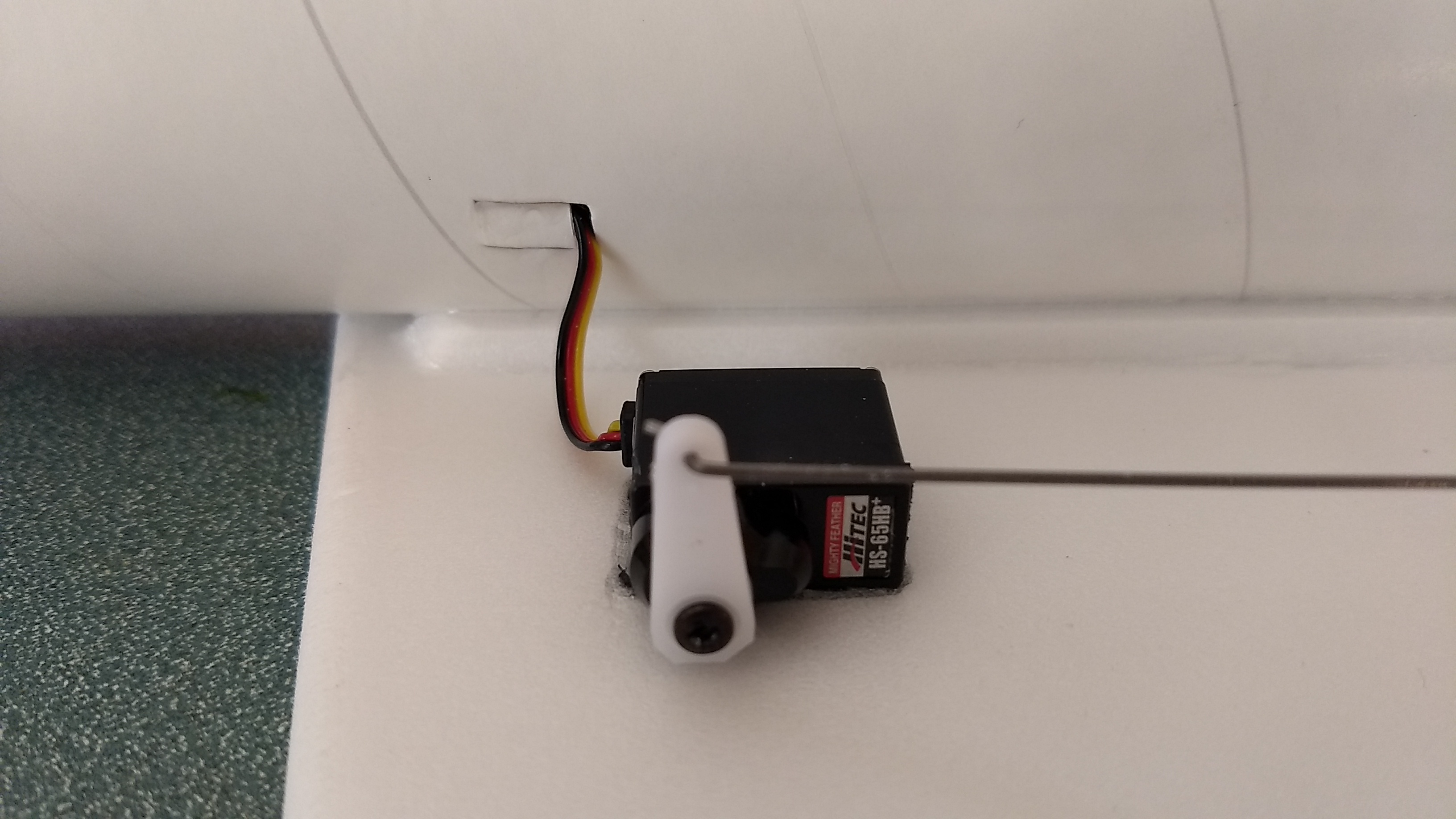
- The servos may be attached to the model using double back servo mounting tape(not included) or by directly gluing the servo to the wing with foam safe CA+. Double back servo tape can loosen over time and with exposure to heat, I prefer to glue the servo in place. With the radio still on, put a moderate amount of glue on the servo, being careful not to get any near the output shaft, and set it in place on the model next to the body tube keeping the control surface centered. Do the same to the other side. Make sure the glue is set before continuing. Note** The servo wire should point toward the front of the model and the servo should be about an inch from the body tube with the pushrod going straight forward. The Servo arm should be about 2″ away from the body tube. This is so that the rail does not drag on the servo or the servo horn when launching. Apply a fillet of glue around the servo/wing to help secure it and let it cure being careful not to get any glue near the output shaft of the servo.
- Attach a 12″ servo extension to each servo. You just need to be able to route the wire to the front of the tube to attach it to the receiver.
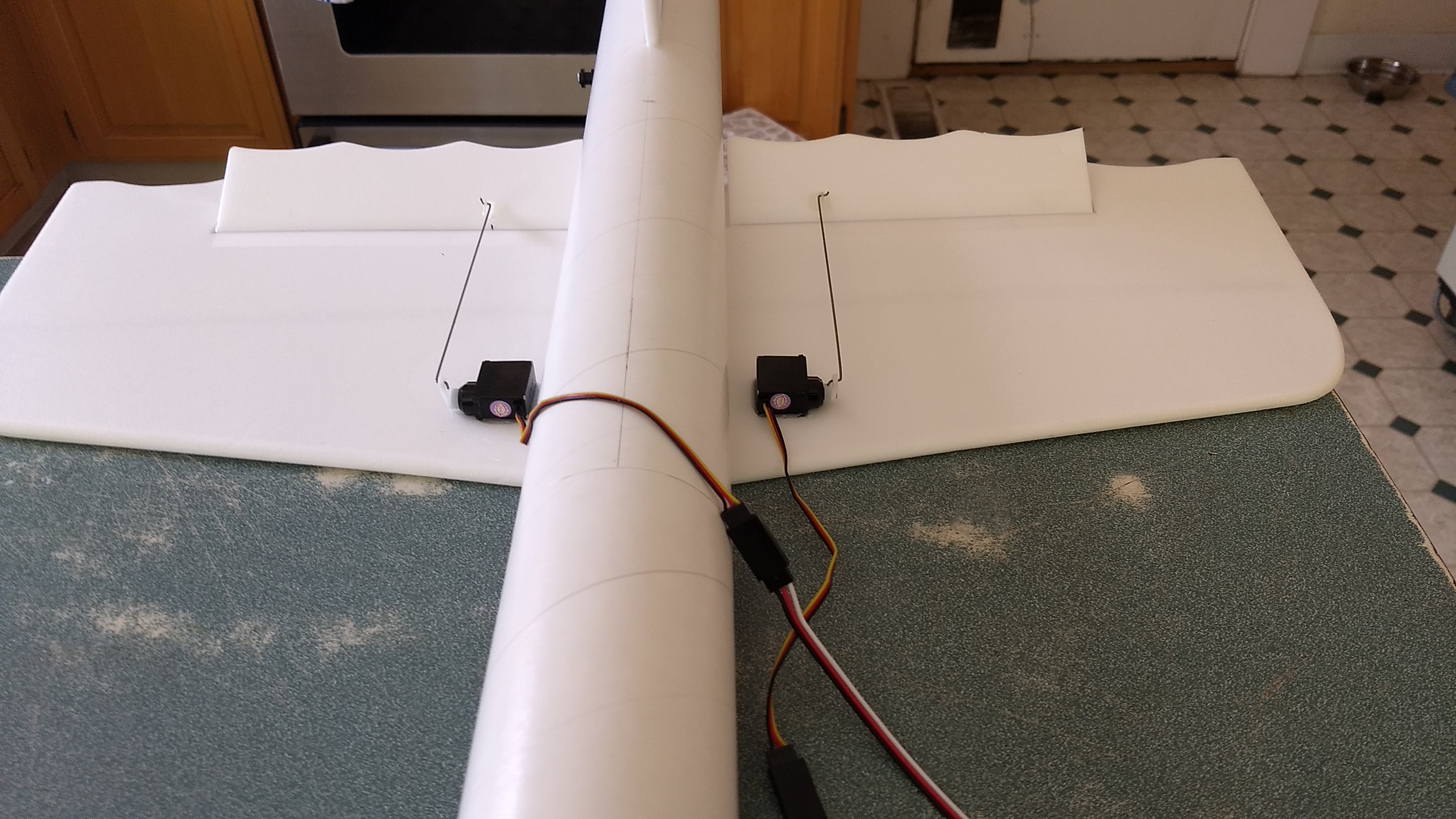
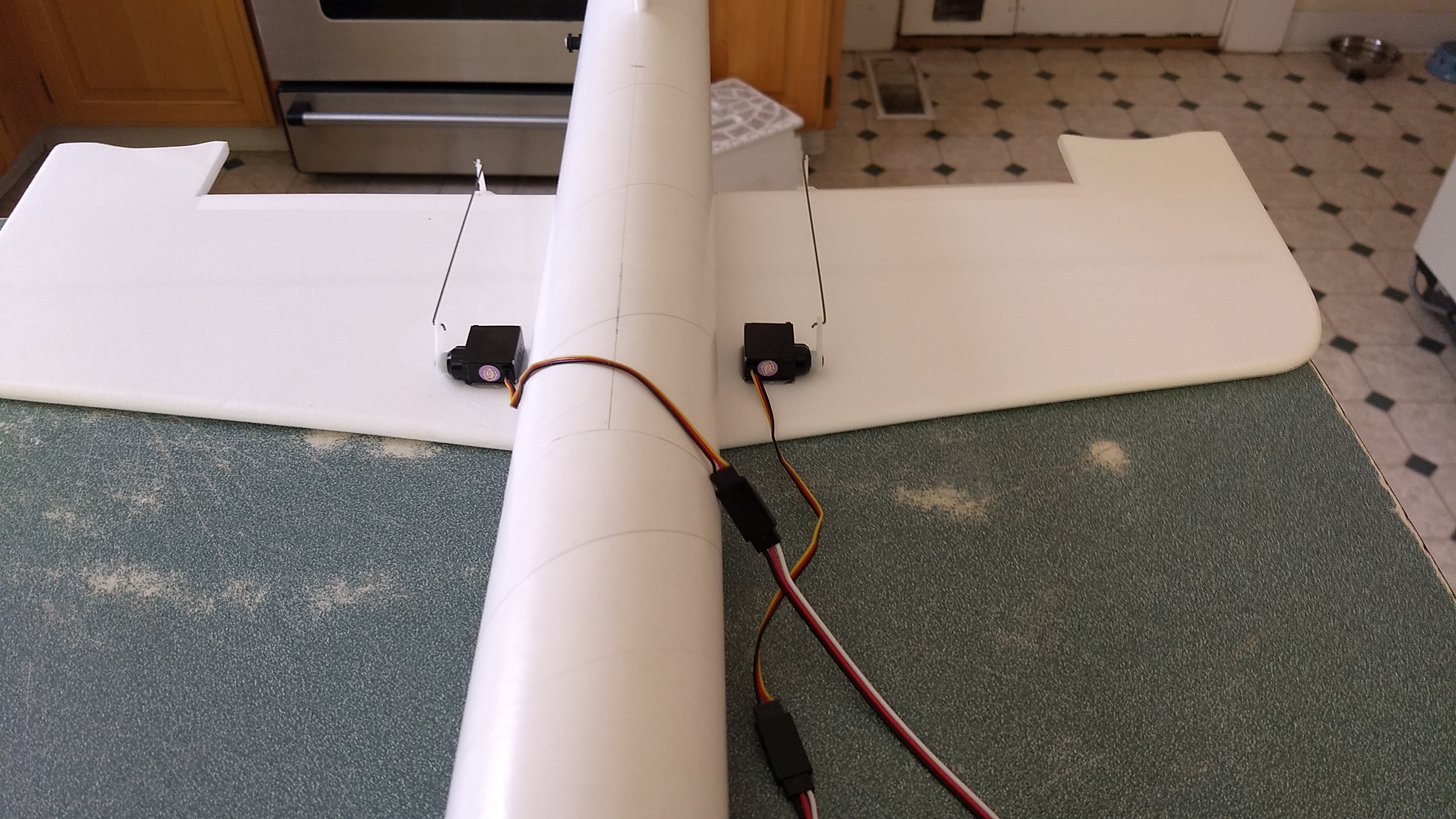
- Make a 1/8″ wide by 1/2″ long slot in the body tube on each side of the body tube near the servo and pass the wires through to the inside and toward the front. On my model I just made a U shaped cut, folded the cardboard forward, inserted the wire then folded the cardboard back over the slot/wire. I then glued the cardboard tab in place. See photo for more clarity.
- Re-Attach the servo wires to the receiver and make sure they are going the right direction.
- Make sure the control surfaces are centered, use trims if needed. Now measure the control surface movement. Full elevator movement should be 5/8-3/4″ in each direction, aileron movement should be 3/8-1/2″ in either direction. Sometimes the foam has a slight curve to it at the wing tips, it won’t affect flight performance. When setting the control surfaces for neutral use the middle of the wing as your guide for what is level.
- If you have a flap/elevator mix you can program up elevator trim for boost and glide. If you can’t set the up elevator trim to a switch on your radio you’ll have to manually put in boost and glide trim using the trim tabs which is hard to do while flying the model. My model needed slight down trim for boost and about 3/16″ of uptrim for glide.
- Install the two interplane struts onto the lower wing at this time, use the wing marks on the lower wing as a guide. The interplane struts will angle forward.
- Use the included Velcro to attach the receiver insde the body tube far enough in that the nose cone won’t hit it. This allows you to be able to remove and replace the receiver if needed for repairs or for removing the servo wires.
- I attached the battery inside the nose cone on the bottom of the shoulder with velcro.
- Lightly sand the upper wing line on the body tube and glue the top wing in place, the interplane struts will help keep the wing parallel to the bottom wing. Make sure it is centered with the marks and make sure the glue is cured before you proceed.
- Glue the interplane struts to the top wing making sure there are no twists in the wings as you do this.
- Install the other two foam reinforcing strips into the wing/body tube joint as you did on the lower wing, again being careful not to push them in too hard and roll the body tube.
- The windscreen is made from scrap cardstock curved to shape and glued to the wing. Below is a pdf file with the windscreen and marking details, you can print that with no borders or page scaling and use that for the windscreen shape or you can apply the silver stickershock decal to cardstock after the model is painted, cut it out and use a clear glue to glue it to the model.
- I can only recommend testors/model master enamel spray at this time, others I’ve tried damage the foam surface. I recommend flat colors as they dry faster and the surface imperfections of foam aren’t as noticable.
- The Model is painted flat red, I masked off the tail and 5″ wide sections on the top and bottom wings spaced about 3″ out from the center.
- Install the receiver and battery
- Insert your heaviest loaded rocket motor into the motor mount
- Support the model at the balance point indicated for boost. I had to mark the underside of the upper wing and angle my balancing rods to go under the top wing with the model upright and get a slight nose down attitude. Use pieces of the included lead weight as far forward into the tip of the nose to balance it, or in the tail as needed. Glue the lead weight in place so it does not shift during flight. Do not try to fly the model too nose or tail heavy. Remember, a nose heavy model flies poorly, a tail heavy model flies once
- If you choose to use the stickershock markings, after application use a hair dryer on hot to warm the markings and them push them down into the foam surface with your finger. They will really conform and stick down well.
- The white strip goes right in front of the wing and covers the body tube joint, I put a black strip on each end of the white stripe, then applied the 1.75″ iron crosses on each side.
- Apply the medium iron crosses on each side of the tail
- Apply the large iron crosses to the top of each wing and bottom of each wing.
- Apply a black stripe on each side of the white wing stripe, this helps to hide any bleed under from the masking.
- The wide black stripe goes about 2″ back from the front of the body tube.
- Apply the nose arrows on each side of the nose cone.
- Apply the two machine guns ahead of the wing on the body tube.
- Apply the silver stripe on the rear of the body tube.
- Apply the silver windscreen to your windscreen.
Flying: See the General Instruction link at the top for flying instructions. Be ready on the first few flights to keep the model straight till you have the trims set perfectly for boost and glide. I found my model was a bit pitch sensitive on boost so I used 70% throw for boost on my dual rate switch, and switched to 100% for glide when I switched in the up trim.
[Download not found]The photos below are for reference but please read through and follow the steps in order as the text is written.
-
- Glue the two body tubes together
-
- glue the body tube to the lower wing
-
- Use the elevons to help center the tube left and right.
-

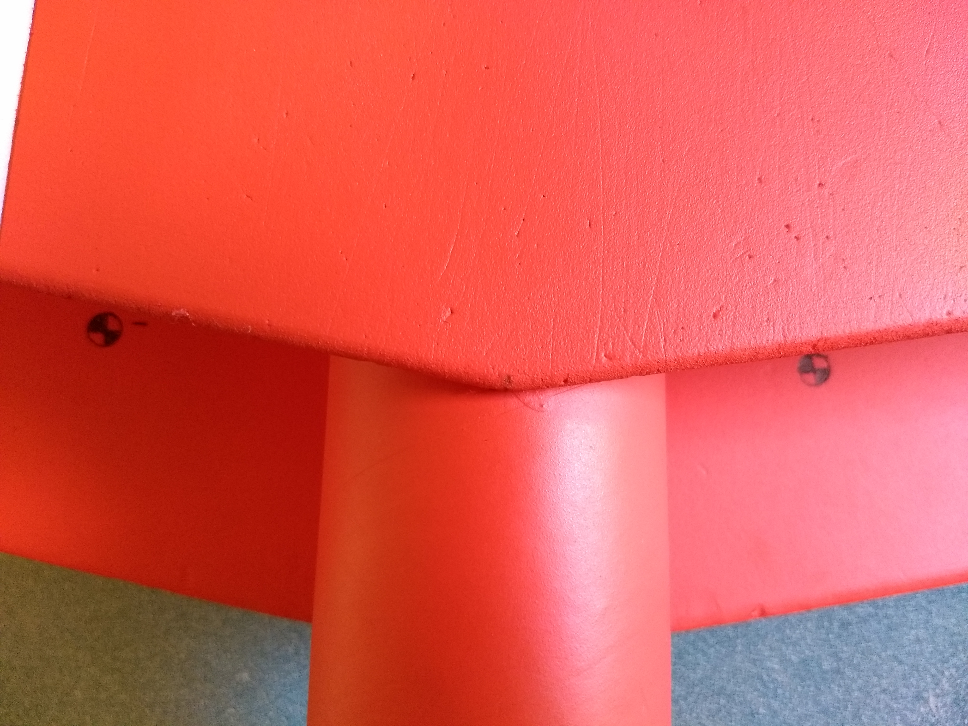
- Install the rear rail button
-
- Install the front rail button
-
- Install the vertical stab
-
- Glue the three foam tabs onto the motor tube, current kits do not use a motor hook, you just use a small piece of tape to friction fit the motor from falling out.
-
- Test fit the motor mount under the vertical stab tab
-

- Glue in place when fit is good, note it is inset about 1/2 inch.
-

- Make sure the verticals tab stays perpendicular to the wing while the motor mount sets.
-
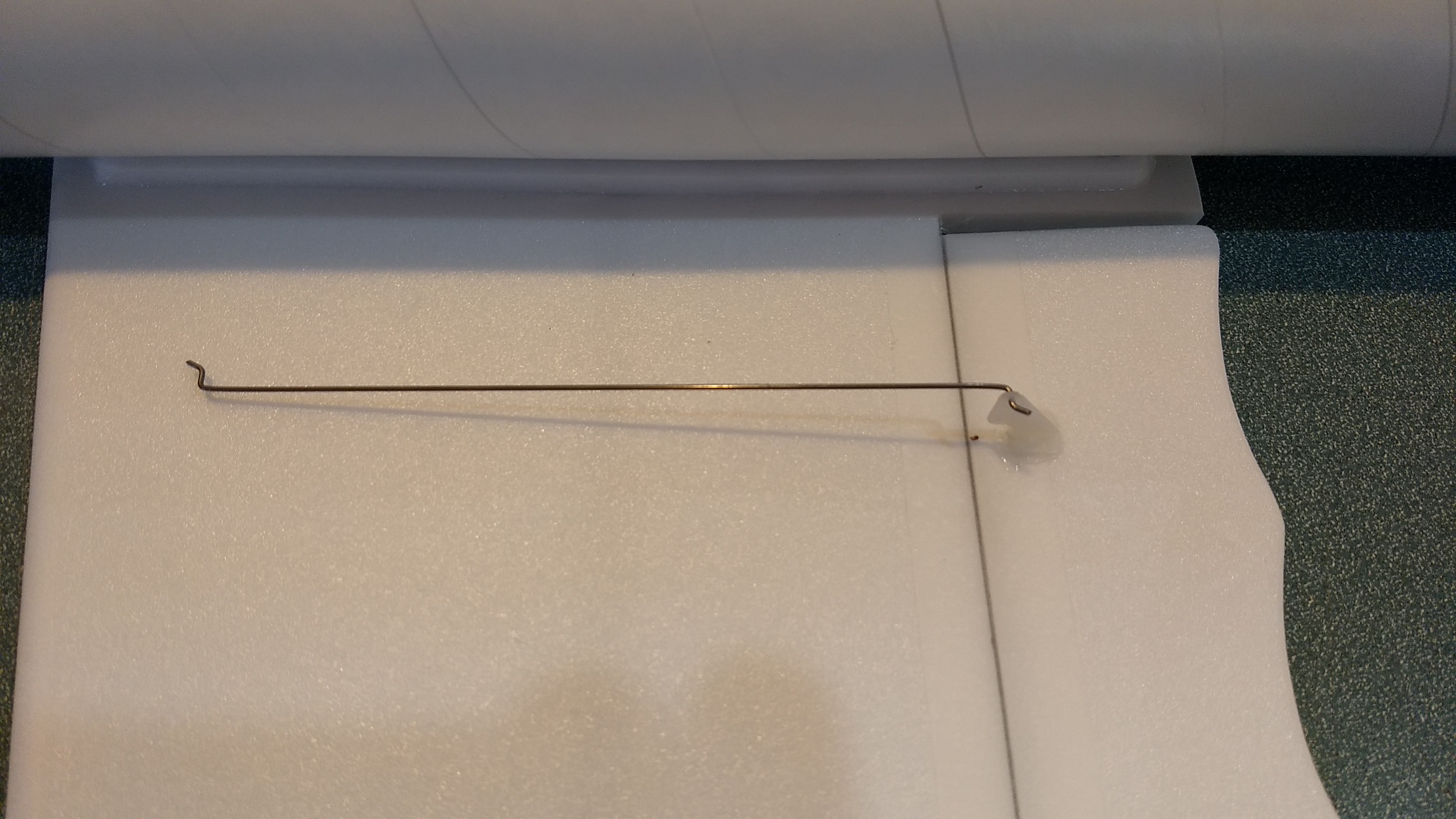
- Install the two pushrods.
-

- Add glue to the prongs of the control horn to lock it in place.
-
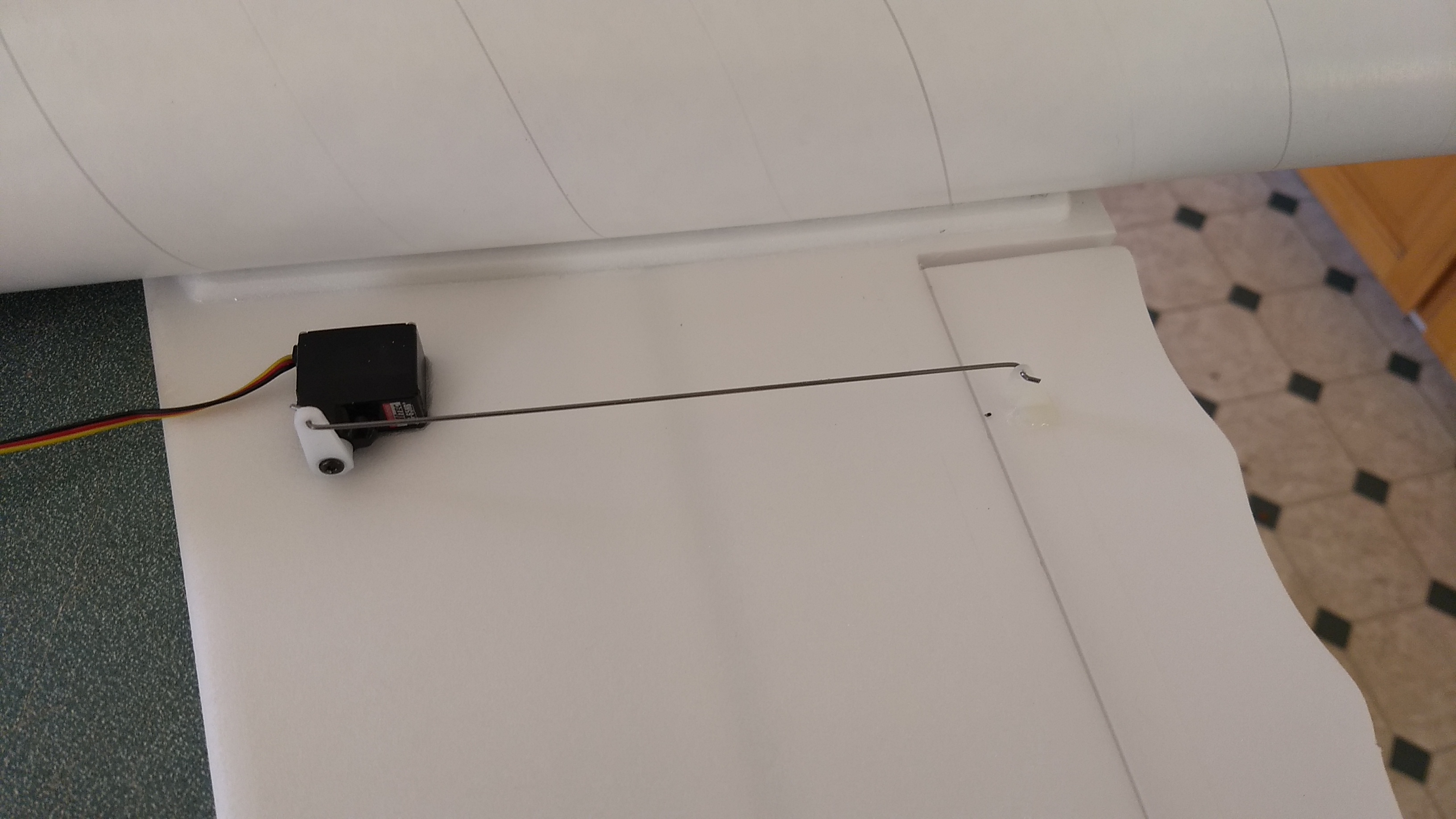
- Install the servo, note the servo is about 1″ away from the body tube and the servo arm is about 2″ away so that the rail will not drag on the servo or arm when launching.
-
- Up elevator
-
- down elevator
-

- right aileron
-

- left aileron
-
- up trim for glide.
-
- route servo wire into body tube via a slot or tab.
-
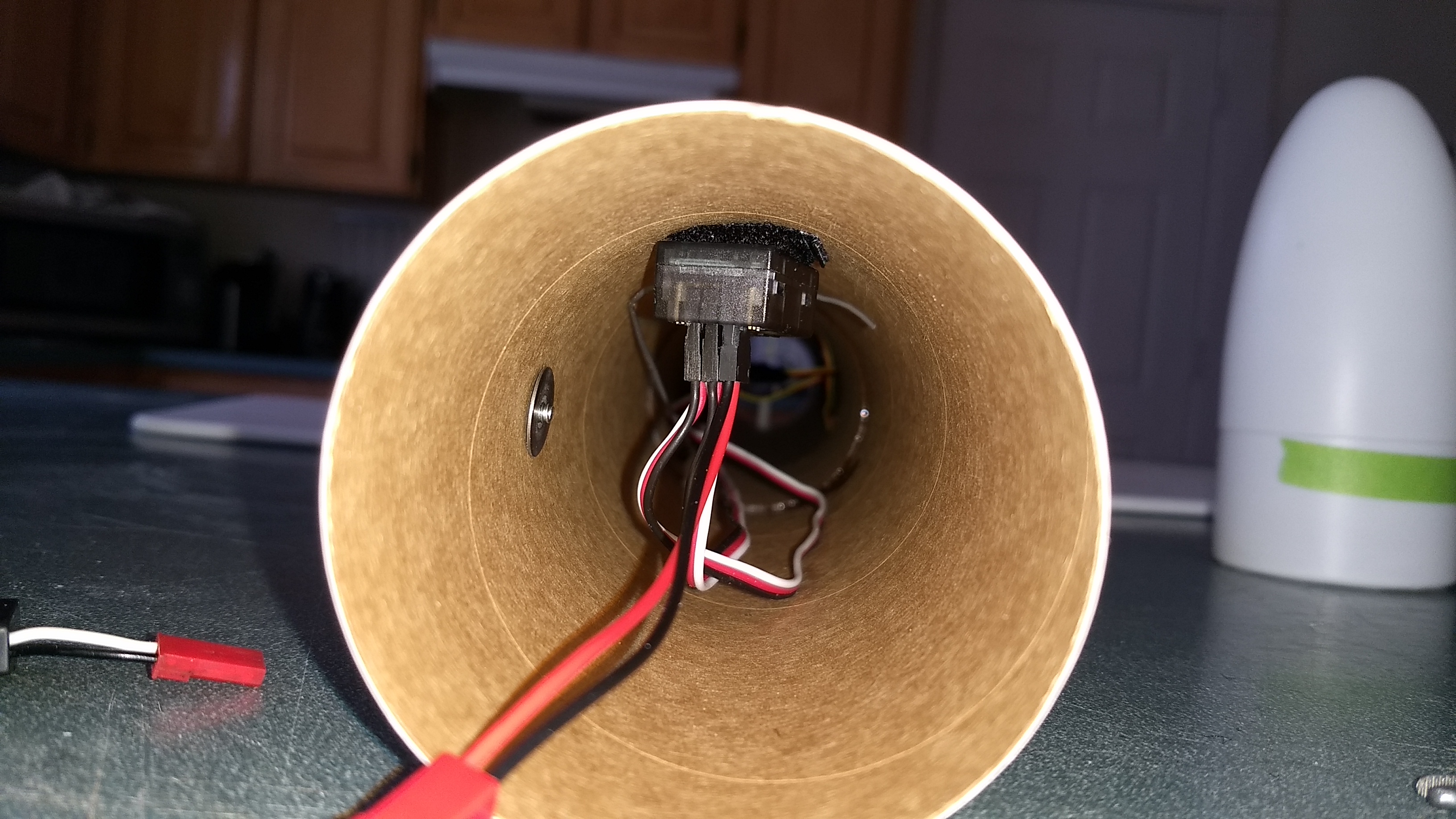
- Install the receiver with velcro far enough back from the front that the nose cone shoulder doesn’t hit it.
-
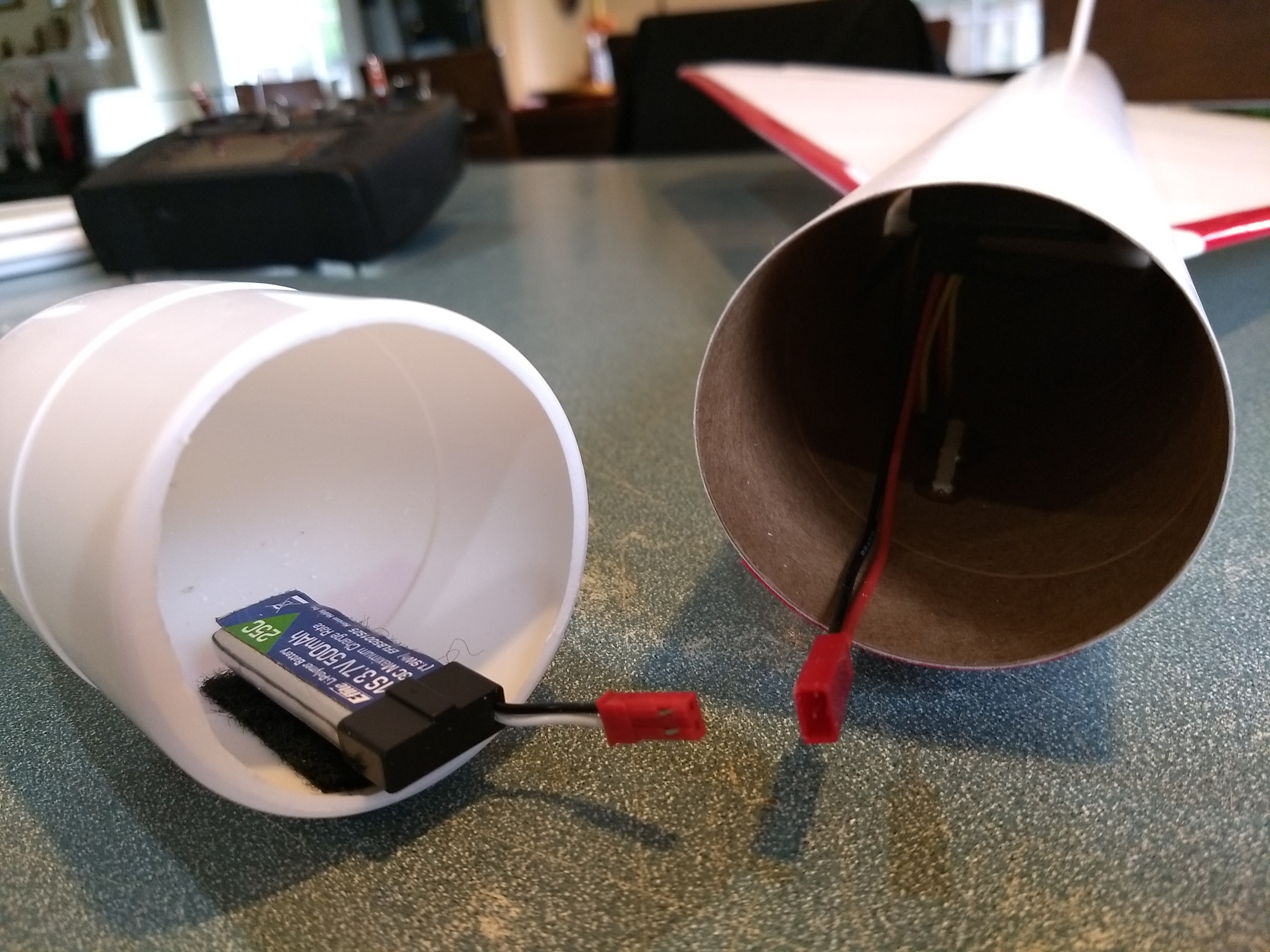
- Battery velcro’d to the inside of the nose
-
- Glue the interplane struts to the lower wing angling forward using the marks on the lower wing as a guide, then glue the top wing to the body tube on the alignment marks, the inter wing struts will help keep the wing parallel to the lower wing.
-
- cockpit window installed
-
- CG location
-
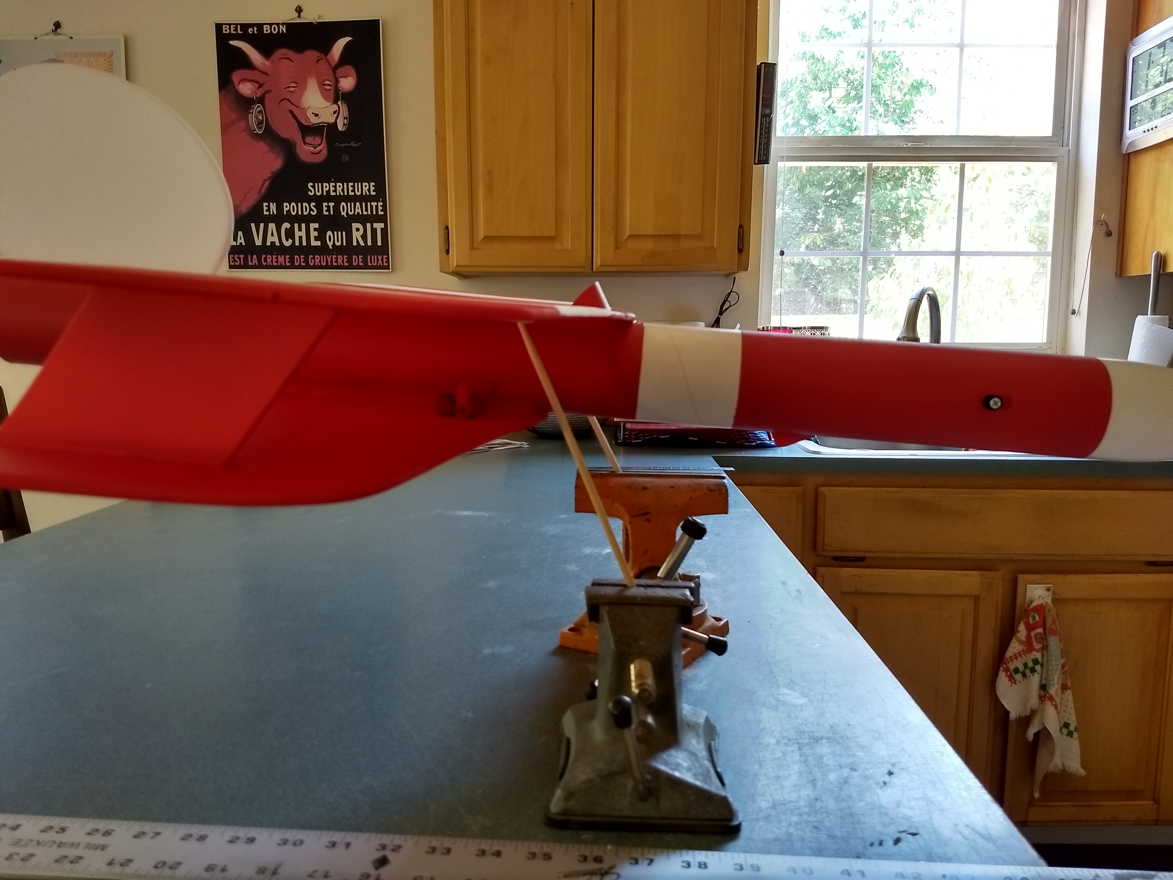
- balancing the model
-
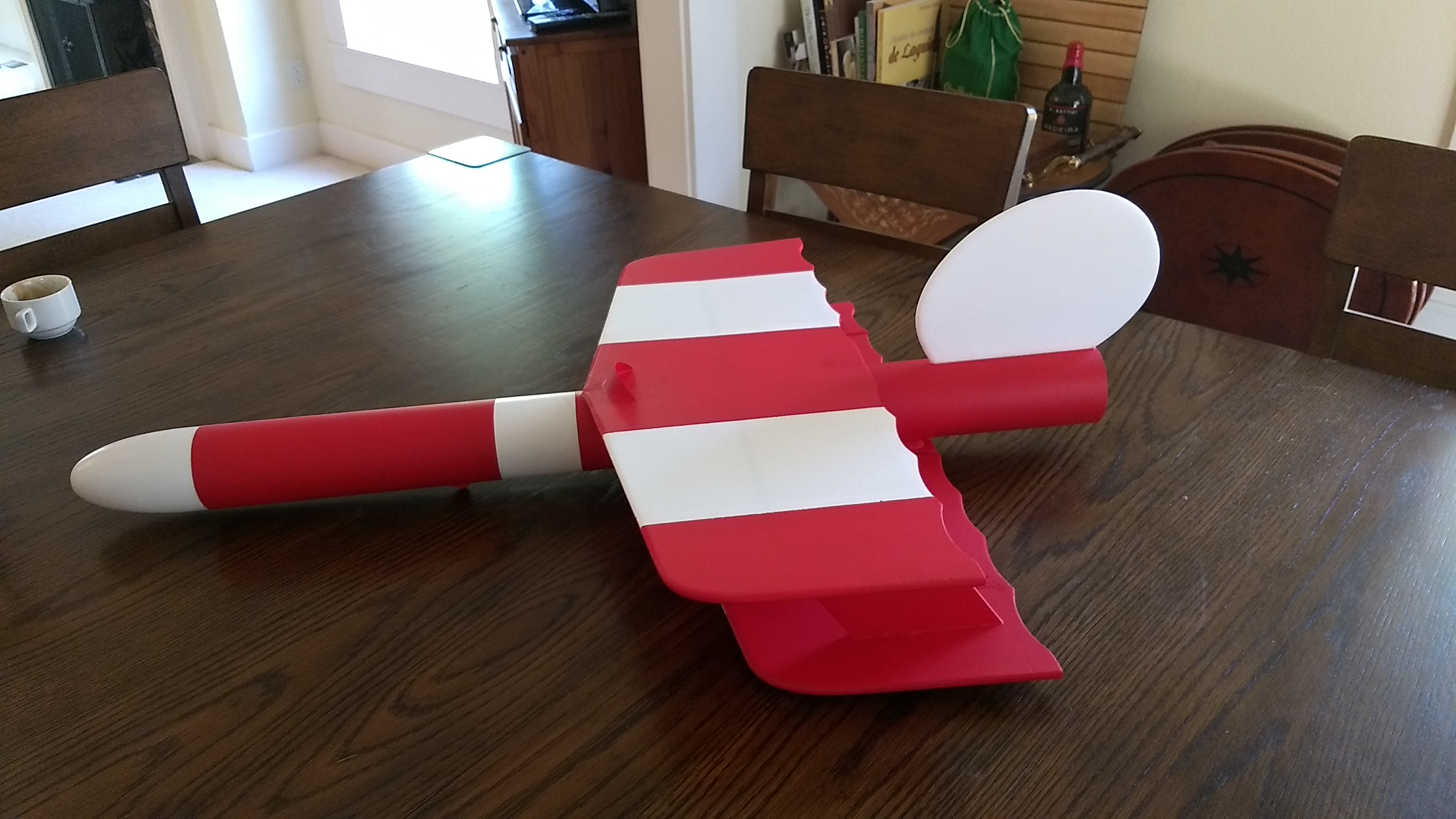
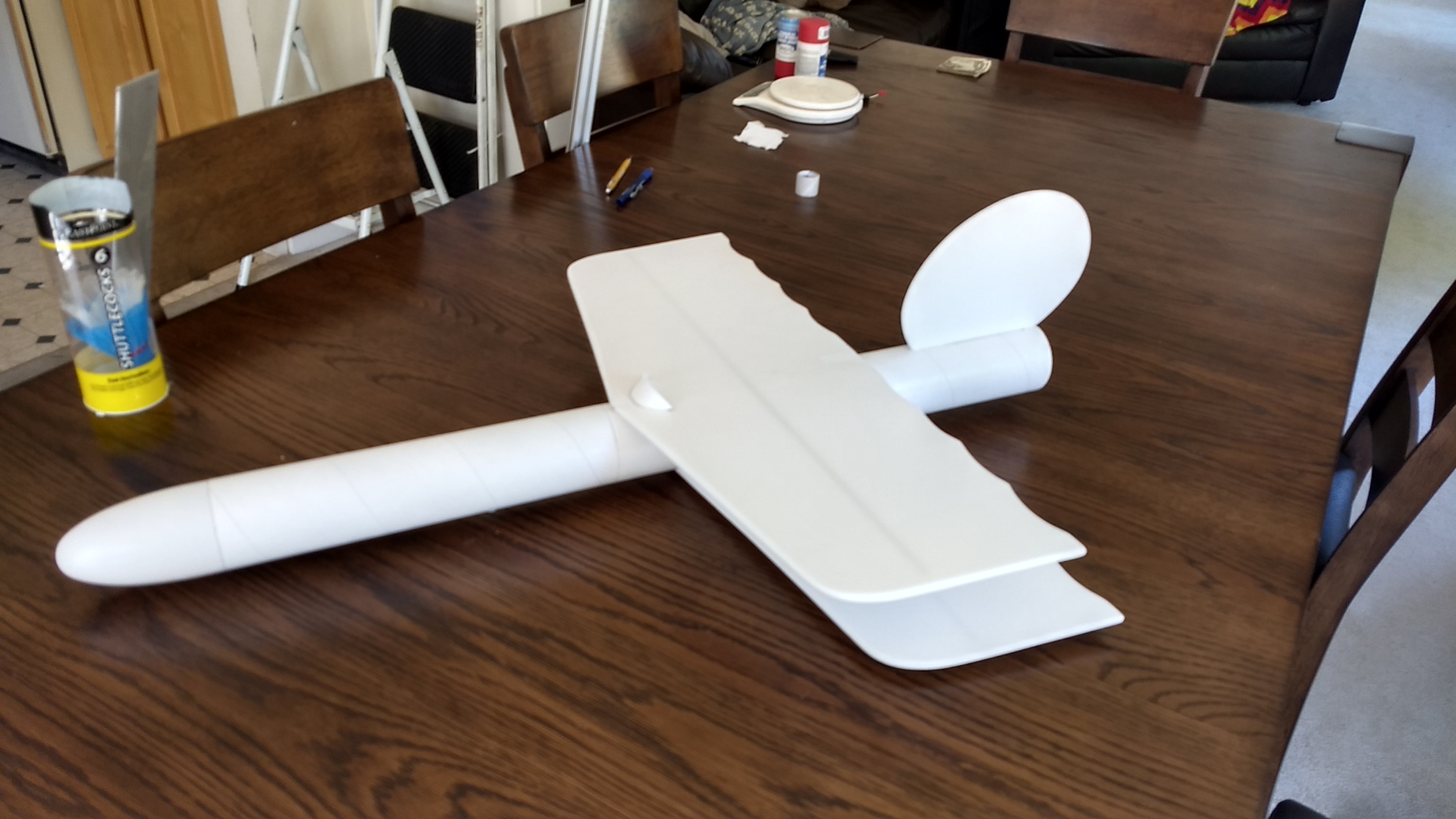
- Model painted ready for markings.
-
- Completed model shown with stickershock23 markings.