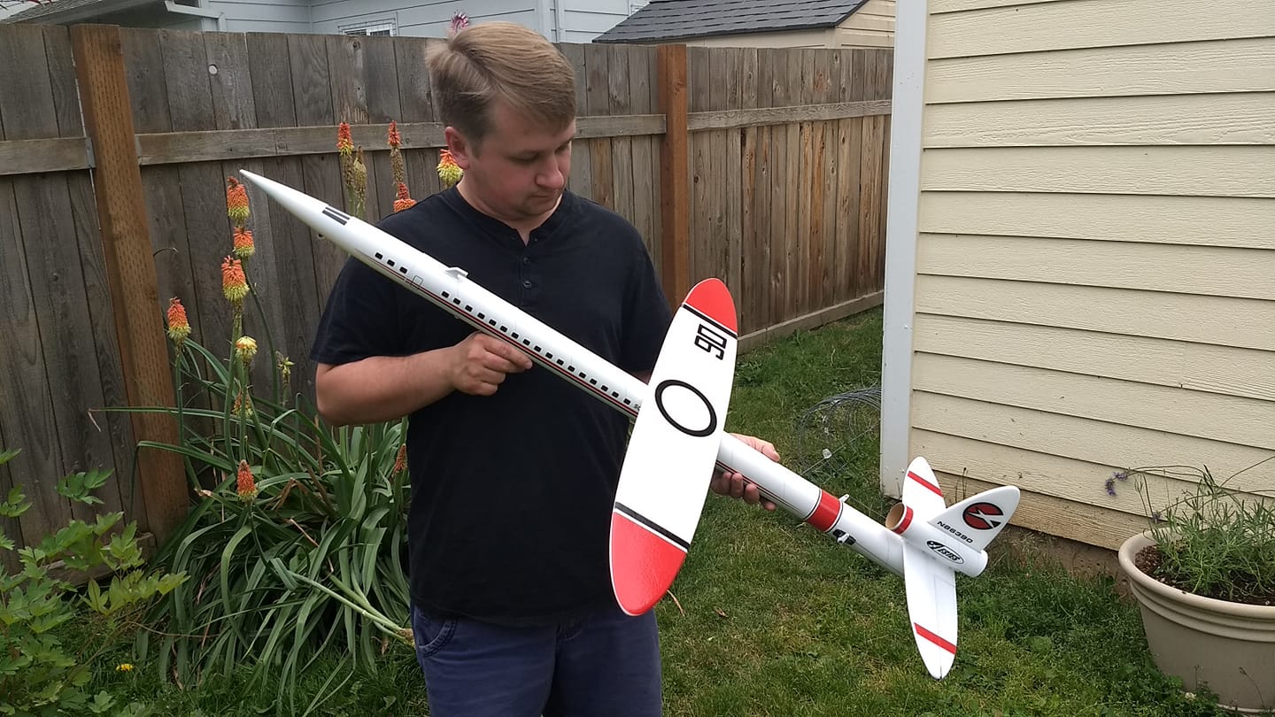
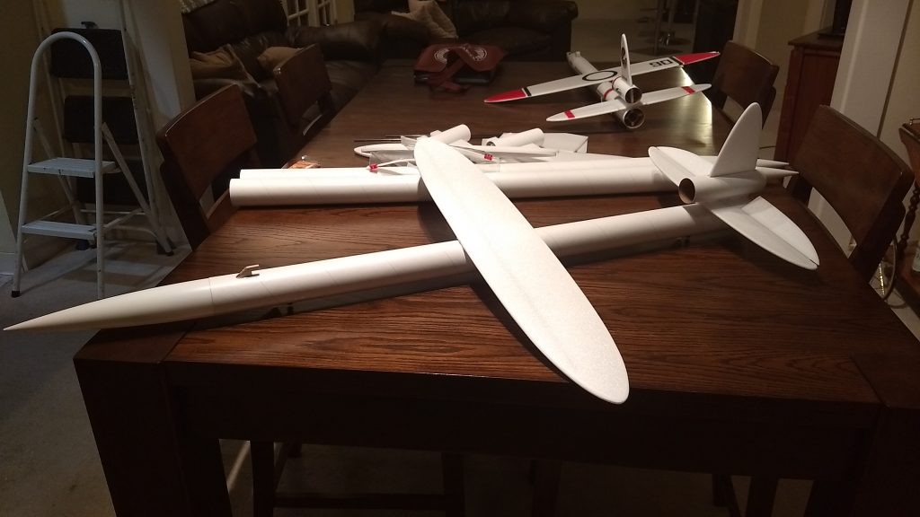
The Scissor Wing Transport RC Rocket glider kit is a 2x upscale modeled after Estes Scissor wing transport free flight rocket glider. It comes with a plastic nose cone, 2″ white tubing for the body and depron wing and tail surfaces. You will need two 10 gram type servos, two 24″ servo extensions, a receiver, and a small 500mah single cell lipo battery with jst connector. You will need a transmitter with delta or elevon mixing and a lightweight sub 10 gram receiver. Please refer to the general instructions link above, then read the instructions completely before starting assembly. The assembly photos are for general reference but may not include every step in the instructions. Everything is white so no paint is required. ST-20 tubing 2″ diameter, 34″ tube length, 44″ length, 28″ wingspan,11 3/8 oz rtf, and 10.2 oz glide weight.
**CG location for fixed wing rocket flight: 1.5″ back from the LE of the wing RTF with motor installed, which should be right on the spar. This model is designed to fly on the 24mm Aerotech E-6 rocket motor only with a very mild long boost and low speed.
***If you choose to modify the kit to fly it as a swing wing, be sure to set the glide CG 1/4″ ahead of the spar with an empty motor casing installed, when you boost with the wing rotated back the CP will move far enough to the rear that the model will be stable. Due to assymetric drag you should put some roll command on the elevons for boost and use an E-18 or F-12 motor to get sufficient speed off the rail, once the model has reached apogee you can flip the wings out. I have not done this modification and so give no guarantees of function or strength of this modification. ***
Welcome to the world of rocket boosted radio control gliders. This is not a model for a novice RC pilot, but anyone who is comfortable with RC flying of a medium speed model should be fine. Read through the instructions, look at the photos and be sure you understand the step before commiting to cutting or glue.
Identify all pieces, the kit should contain:
1 wing
1 24″ long by 1/8″ spar
1 4″ long by 3mm spar
1 horizontal stab with spar installed and surfaces hinged.
1 vertical stab
1 vertical stab tube 5 3/8″ long by 1.6″
1 Nose Cone
2 pushrods with control horns.
2 long and 2 short foam reinforcing strips for the wing/tail body tube joint.
2 body tubes
Motor mount
3 foam centering strips for motor mount.
Velcro(for battery and rx/bec attachment)
2 Rail buttons with t nuts/screws
2 landing skids
Battery adapter for 1s Lipo to rx
Lead weight
Spare foam
Notes before starting:
Reference to CA+ means foam safe CA+, normal CA+ will melt the foam! Normally you need to use accelerator to get the CA to set on the foam since there is nothing for it to soak into and activate.
You may use 220-320 grit sandpaper and a sanding block to slightly round or taper the edges of the foam if you prefer that look. It will not markedly impact the flight performance either way. Be very careful and use a light touch, it is very easy to catch the foam on the edge of the paper and tear the foam. Do any sanding before assembly.
Epoxy is not needed in this model. Weight is critical and the model is designed for the thrust and flight loads. Weight in the rear end is bad and will require additional weight in the front of the model.
Assembly:
- Body Tubes. One tube will have a coupler glued in place. Glue the other tube onto the coupler, make sure the small arrow marks are aligned on the two tubes, that will ensure the wing mark and rail button marks are properly aligned. Use CA+ sparingly.
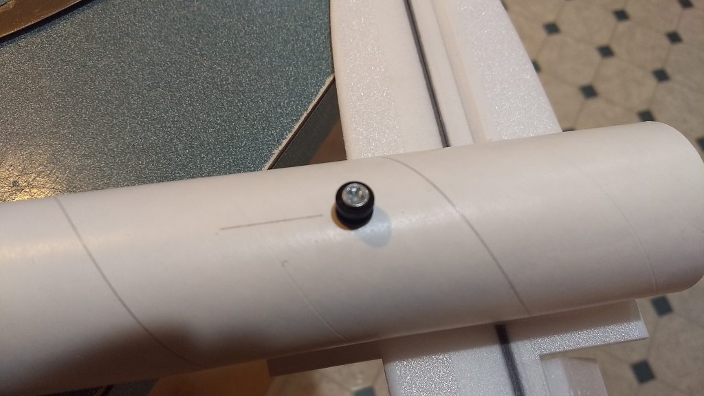
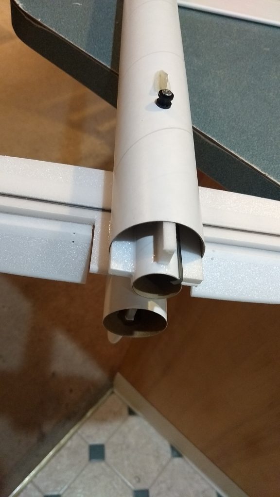
- Make a hole and insert a T-nut into each pre-marked RB(rail button) location on the bottom of the body tube and then screw in the rail button with the included screw. It helps to set the t nut on a table knife and insert it into the model and hold it in place while you put the rail button pieces in place.
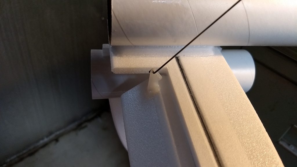
- Mount a skid in front of each rail button. Make two starter holes, make sure the skid is not too far forward to interfere with the nose cone shoulder and does not hit the rail button. Make sure they are aligned with the rail buttons. Glue in place with CA+. The skids should fit into the slot in the rail and not drag, and should contact the ground before the rail button to protect them on landing.
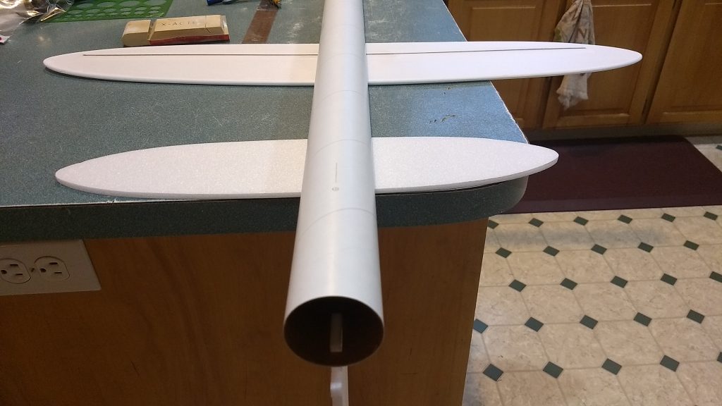
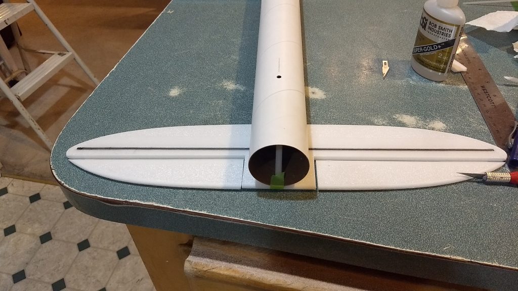
- Unfold the wing and glue it at the taped joint
- Glue the two spars in the grooves in the wing, then tape over them with blenderm tape. The long spar is at the front of the wing.
- If you are going to pivot the wing skip steps 6, 7, 8 and 9 and refer to this general guidance in steps a-c below, otherwise continue on to step 6
- Add a 1/16″ ply 3″ diameter disk on the top and bottom of the wing to support the wing joint and tie into the spars, then create your pivot support and mount the wing as desired. the pivot location should be right at the joint between the two body tubes, this will position the wing for optimum glide.
- The rear of the wing will fit under the rear vertical stab tube and the front will be held captive by a ply plate. The ply plate notch is not cut since the height of the notch depends on how high your pivot stand and wing are. Cut the notch and locate the plate once the wing is installed to be sure you have it in the right location.
- Lightly sand the top wing line on the body tube to help adhesion of the glue.
- Apply foam safe CA+ onto the wing line and also down the center line of the underside of the wing. The underside has the spar visible.
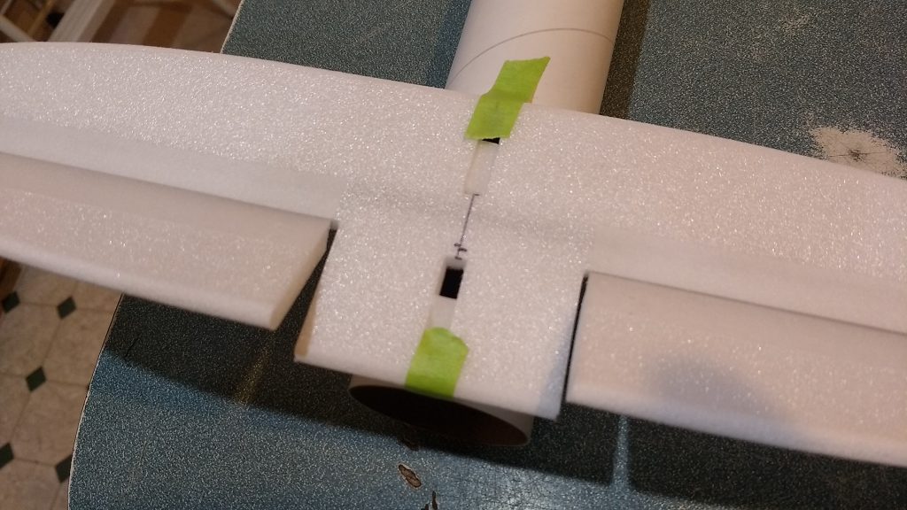
- Attach the wing onto the body tube keeping it straight and keeping the rear of the wing aligned the marked wing line on the body tube. The front and rear wing locations are marked. You can use a little bit of tape to hold the wing in place in the front and back so it doesn’t slide forward/backward. Then quickly flip the wing/body over onto a flat surface. Set the horizontal stab under the tail so that the wing/body tube can lay flat. Make sure the tube is not rotated to one side or the other, I measured from the side of the body tube to each wintip to make sure the tube is not rotated.
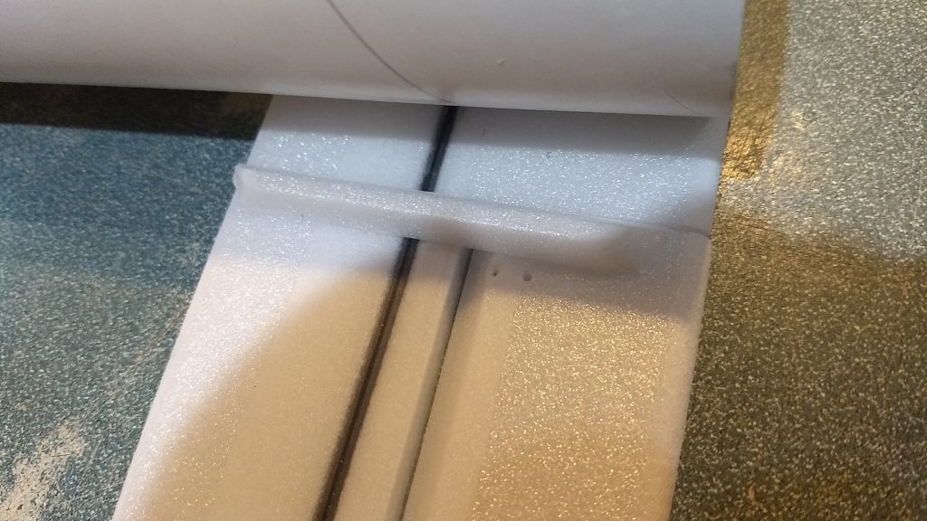
- Glue the two long reinforcing strips on either side of the wing, against the body tube and the wing. Don’t push this in too hard as it can rotate the body tube relative to the wing. All this piece does is to act as a filler to allow you to put additional CA fillets against the wing and body tube to help it attach firmly. The angled cut goes into the wing joint. Apply a fillet of CA+ onto the strip and wing/body tube joints.
- Cut two 1/2″ wide by 1″ long strips out of the spare foam, these help located the horizontal stab for gluing.
- Lightly sand the area where the horizontal stab sill sit.
- glue the horizontal stab to the body tube, you can insert the two foam strips flush with the top of the stab to locate it in place, then flip it upside down to make sure it is level with the wing. Make sure the notches in the stab and body tube are aligned front and back and side to side.
- Add the small reinforcing strips on either side like you did on the wing, these go into the joint where the horizontal stab meets the tube.
- Remove the small foam locating strips and make sure the notches are clear.
- Carefully insert the vertical stab into the notches in the stab and into the body tube. Make sure it is perpendicular to the stab and then glue in place.
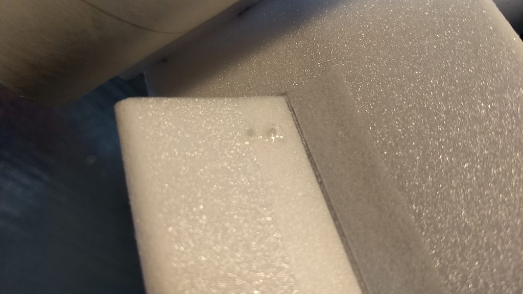
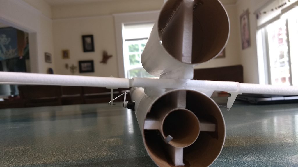
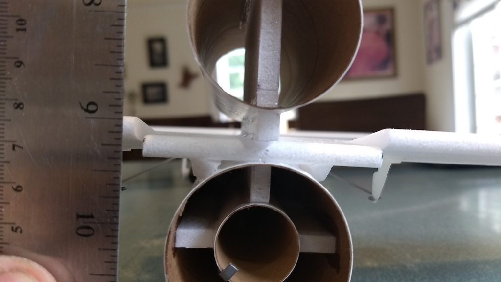
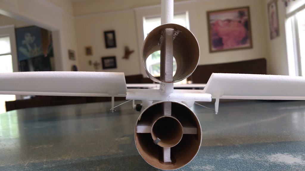
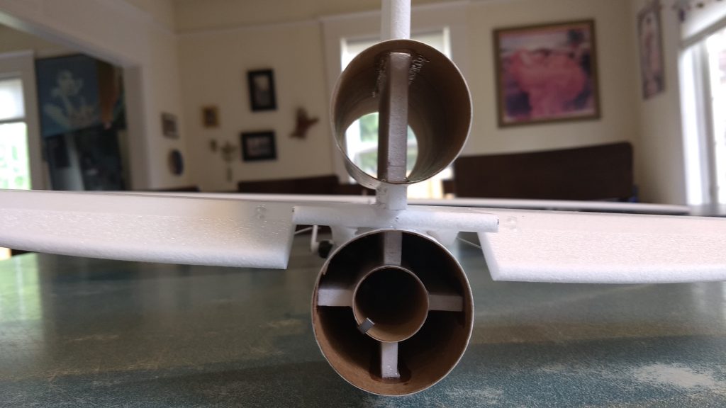
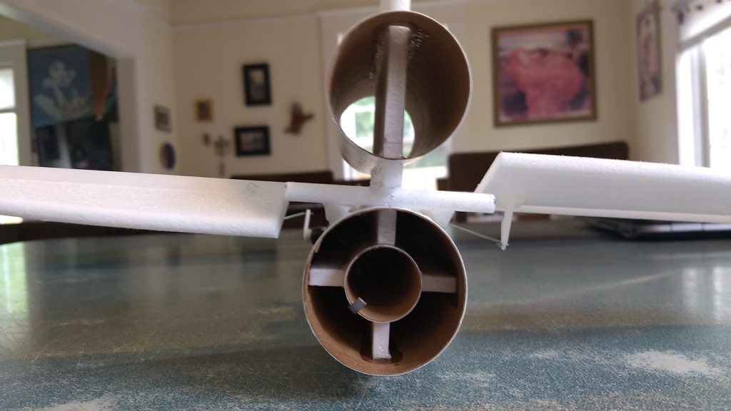
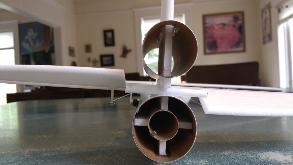
- Slide the dummy motor tube over the stab and down to the little stubs of foam that keep it about 1/4″ above the stab. Glue it in place with a small amount of glue. The motor tube should stick forward more than to the rear, the rear should only extend about 1/2″ past the rear of the stab.
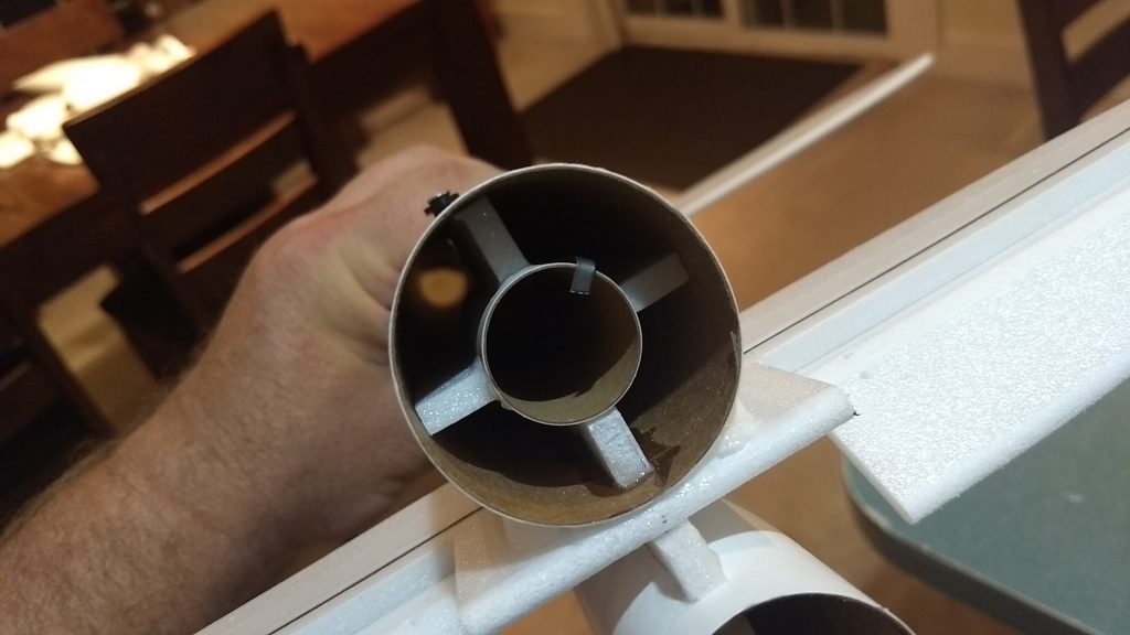
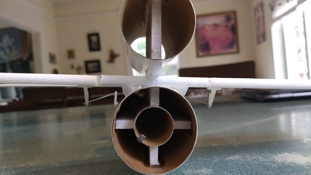
- Glue the three foam centering tabs onto the motor mount. You want two directly opposite each other and one at 90 degrees to the other two. The fourth tab will be the vertical stab tab that sticks down into the body tube. Do not glue to the motor hook as that needs to move freely.
- Test fit the motor mount into the body tube. Lightly sand the foam strips till it will insert snugly and fit under the vertical stab tab.
- Glue the motor mount into the rear of the model, the motor mount can be inset about a half an inch from the rear of the body tube.
- Note the motor hook is glued and taped at the front, make sure you insert it so that the free end of the motor hook is at the back so you can lift the motor hook to release the spent motor.
- Glue a pushrod/control horn into the bottom each elevator half in the pre-made holes. I have the pushrod on the outside away from the body tube so I can remove it to put the z bend in for the servo.
- Apply some foam safe CA+ to the top of the prongs to lock them in place.
- Note the servo locations on the body tube, adjust them for your servos and carefully cut out to fit your servos and not be loose.
- Notch and glue your retaining block the the top of the model in the location that is correct to capture the wing, or in the spot marked on the tube if just for decoration.
- The basic construction is now complete.
Radio Installation
Note: Your radio needs to be configured for Delta mixing, this means that the servo arms will move the same direction during elevator stick movement and opposite for aileron stick movement. Connect your servos to the receiver one in the aileron connection and one on the elevator connection and apply power. Use a servo arm at least 9/16” long Zero out any trim settings on the transmitter.
- Attach a 24″ servo extension to each servo.You just need to be able to route the wire to the front of the tube to attach it to the receiver. Route them into the servo pocket in the body tube toward the front and install the servos. Install the servos so that the electrical wire points forward. and so that the servo horn is pointing up.
- Attach the servos into the receiver at the front of the model.
- Mark the place where the z bend needs to go when the control surface is level. Remove the servo. Remove the pushrod from the control horn and put a z bend at the location marked. Reinstall the pushrod into the control horn and into the servo horn. Install the servo into the pocket and glue it in place. Repeat for the other side. Adjust your sub trims so that the control surfaces are level.
- Moving the transmitter stick back(up elevator) should move both stabilizers trailing edges up. Moving the transmitter stick to the right should move the right elevator up and the left down. If you can’t get the servo reversing to give you the right polarity try swapping aileron/elevator inputs to the receiver If that is correct, continue.
- Now measure the control surface movement. Full elevator movement should be 5/8″ in each direction, aileron movement should be 1/2″ in either direction.
- If you have a flap/elevator mix you can program up elevator to a switch setting. The model needs approximately 3/16-1/4″ of up elevator trim during glide. If you can’t set the up elevator trim to a switch on your radio you’ll have to manually put in boost and glide trim which is hard to do while flying the model. My model needed a very tiny bit of down trim for boost.
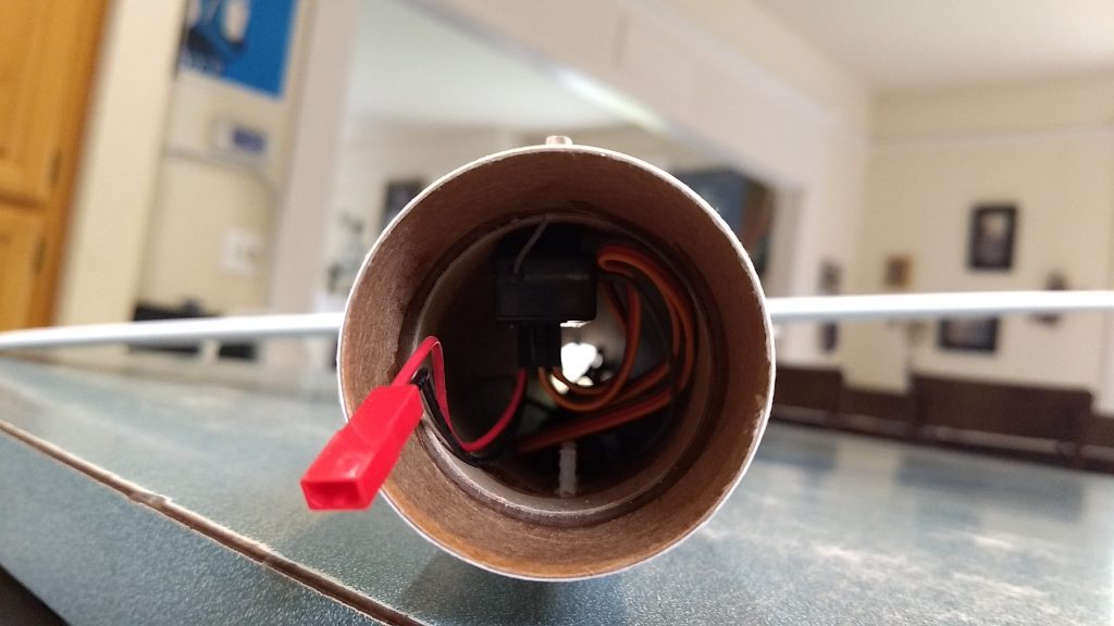
- Use some of the included Velcro to attach the battery in the nose cone. Attach the receiver inside the front of the nose cone behind the nose cone shoulder/shelf using the remaining velcro but not so far the battery wire can’t reach the battery.
- Insert your heaviest loaded rocket motor into the motor mount and install the battery.
- Support the model at the spar. I use two pencils with the eraser pointed up and held in place with a small hand vice. Place the model on the pencil erasers on the balance point indicated above. Use the included lead weight to balance it. Do not try to fly the model with it balancing it behind this point. The adage is, a nose heavy model flies poorly, a tail heavy model flies once
- My model needed approximately 1.25 ounces of nose weight. I simply taped a baggie to the outside of the nose cone till I figured out how much I would need, then put the lead shot into the nose and put drops of CA to hold it in place. Verify your final CG again.
- If you use stickershock cut vinyl markings, It helps once applied to use a hair dryer on hot to soften the material and then push it down onto the model with a towel. It helps it conform and stick much better.
- Flying: See the General Instruction/Information link at the top for flying instructions. Be ready on the first few flights to keep the model straight till you have the trims set perfectly for boost and glide.
-
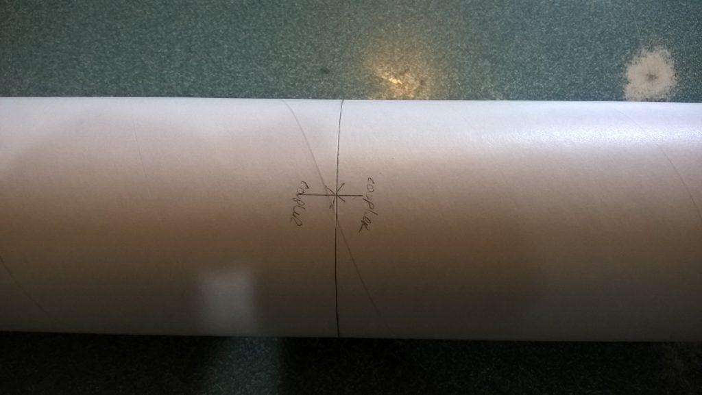
- Join the two body tube pieces so that the arrow marks align.
-
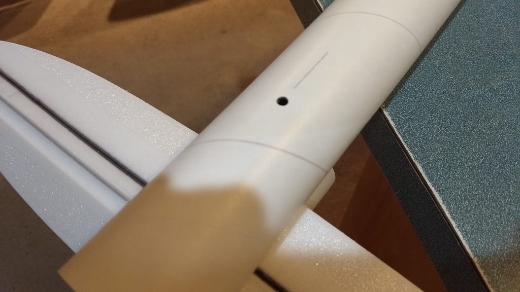
- Make rear rail button hole
-
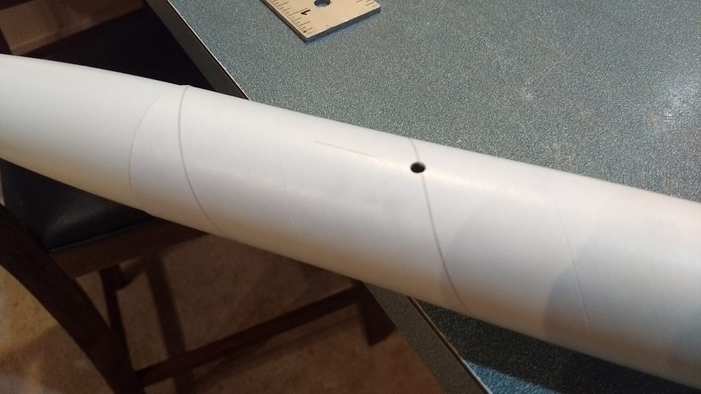
- make front rail button hole
-
- install front and rear rail button
-
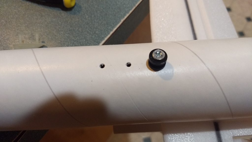
- make holes for skid
-
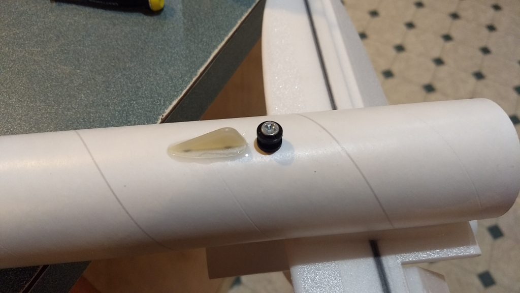
- install skid just in front of rear rail button
-
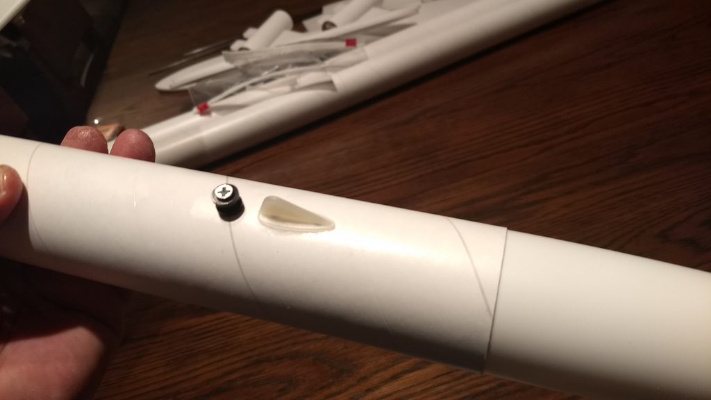
- install front rail button and skid.
-
- Glue the wing in place making sure is is flat with the horizontal stab and the wing tips are equal distance to the front of the body tube.
-
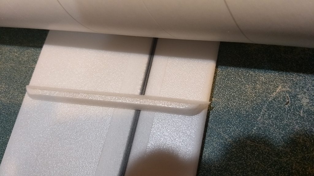
- Install the short foam gussets on each side of the stabilizer/body joint and long gussets on each side of the wing/body tube joint.
-
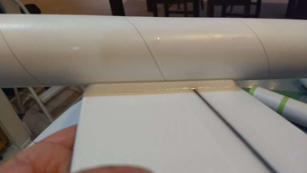
- Gussets installed
-
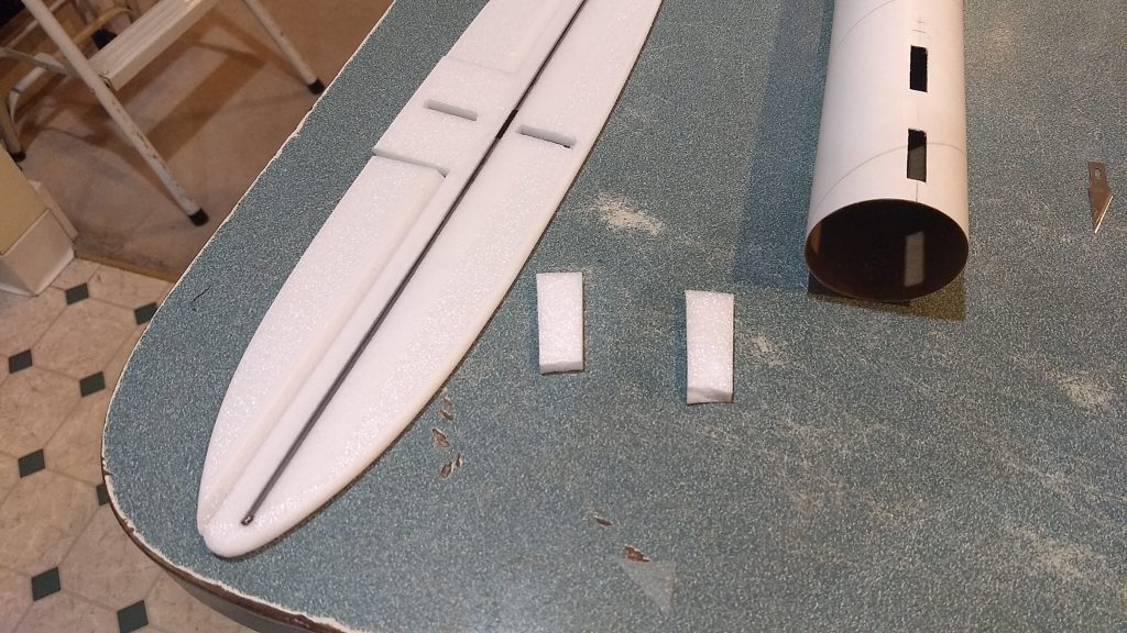
- cut two 1/2″ by 1″ long strips to help align the horizontal stab
-
- glue the horizontal stab in place using tape
-
- lay the model upside down to make sure the stab is flat and use a triangle to make sure the body tube bottom is vertical to the stab.
-
- add the gussets on each side of the stab.
-
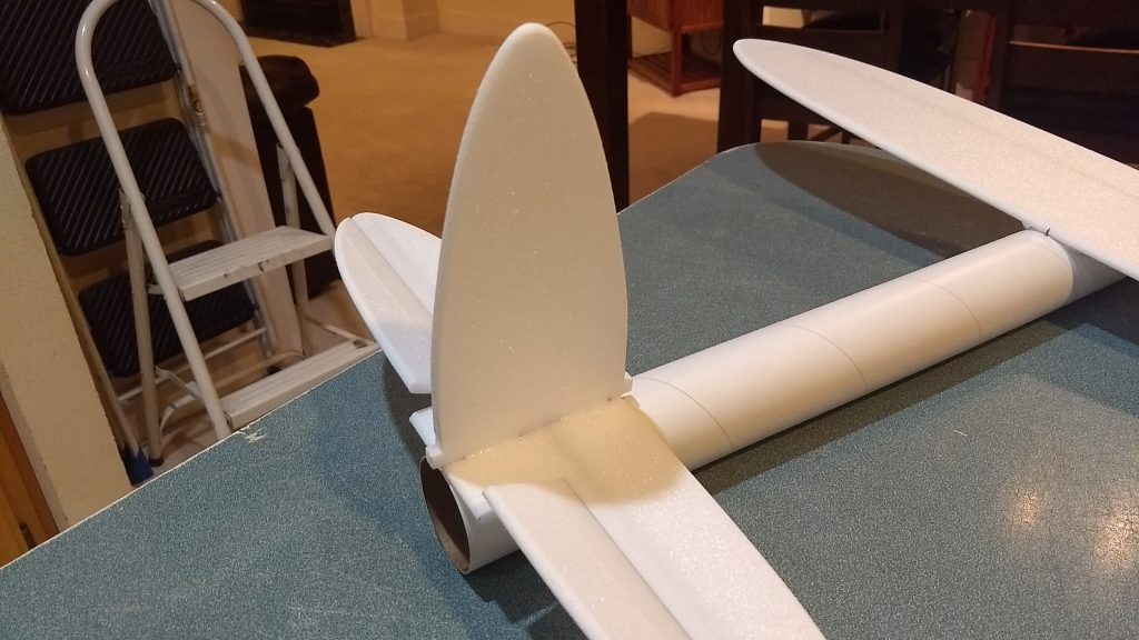
- remove the foam locating tabs and glue the vertical stab in place.
-
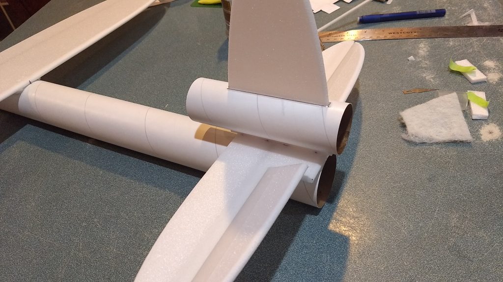
- Slide the stab into the short tube and glue in place. Test fit the stab into the slot in the horizontal stab and glue in place with the longer portion of the tube pointing forward.
-
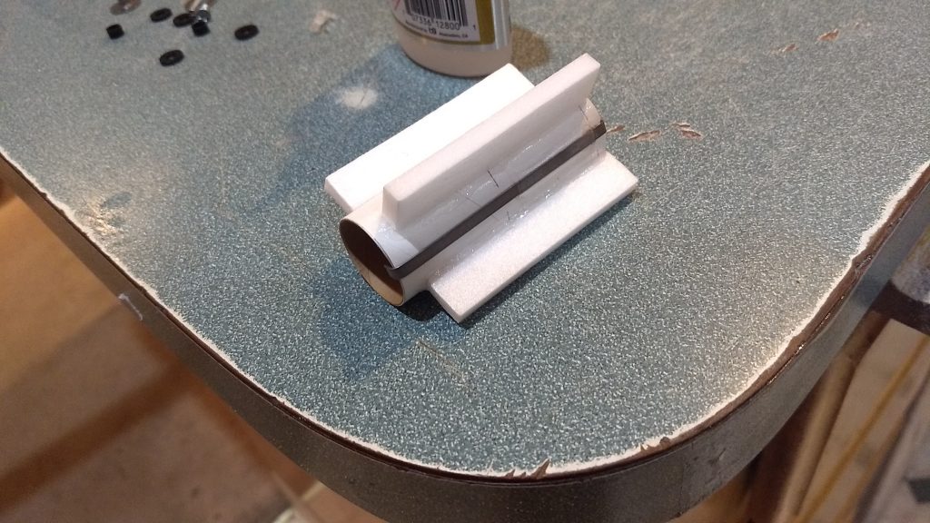
- glue the three centering strips onto the motor mount as shown
-
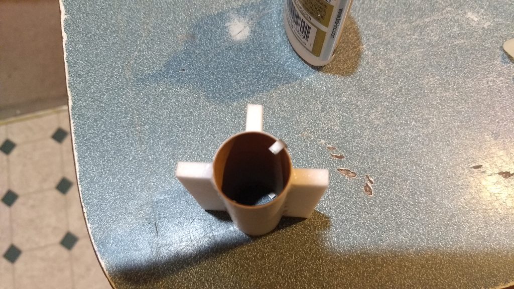
- motor mount showing how the tabs are offset from the motor hook
-
- test fit the motor mount into the model, sand the tabs if needed till it slides into place under the vertical stab tabs
-
- glue in place recessed about half an inch.
-
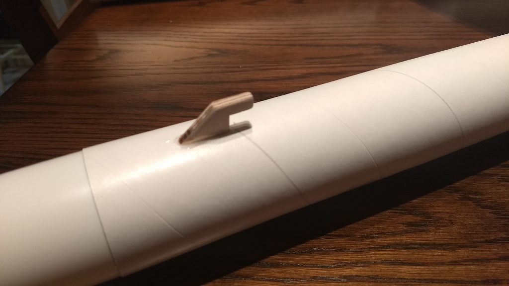
- Glue the wing hold down approx 1″ from the front of the body tube.
-
- glue in control horn into the bottom of each control surface
-
- add glue on the prongs on top of each control horn/suface
-
- Completed airframe
-
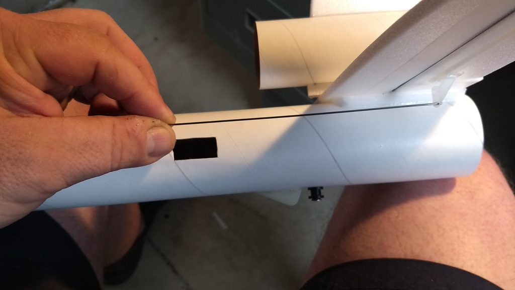
- cut pockets for your servos making sure the control surface will be level when the servo is in place.
-
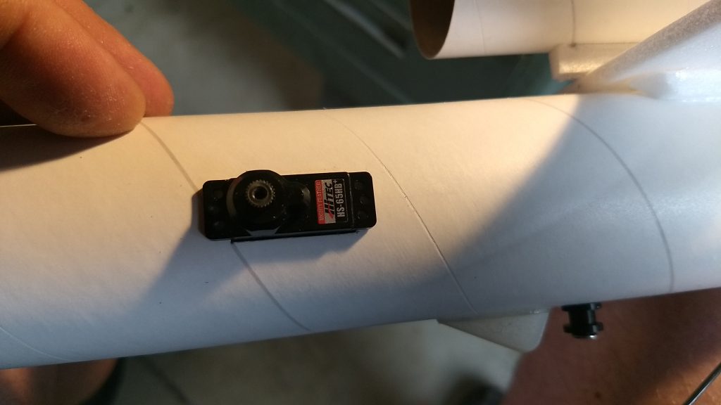
- set servo in pocket cut into body tu
-
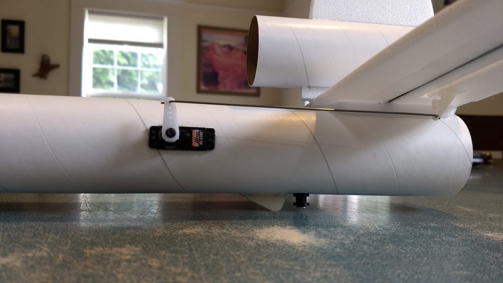
- Install the servos and make sure the control surfaces are level, note servo arms point up. Connect the wires to the receiver and power up the radio, ensure movement and then glue servos in place.
-
- Run servo wires to receiver and mount receiver with velcro inside the body tube.
-
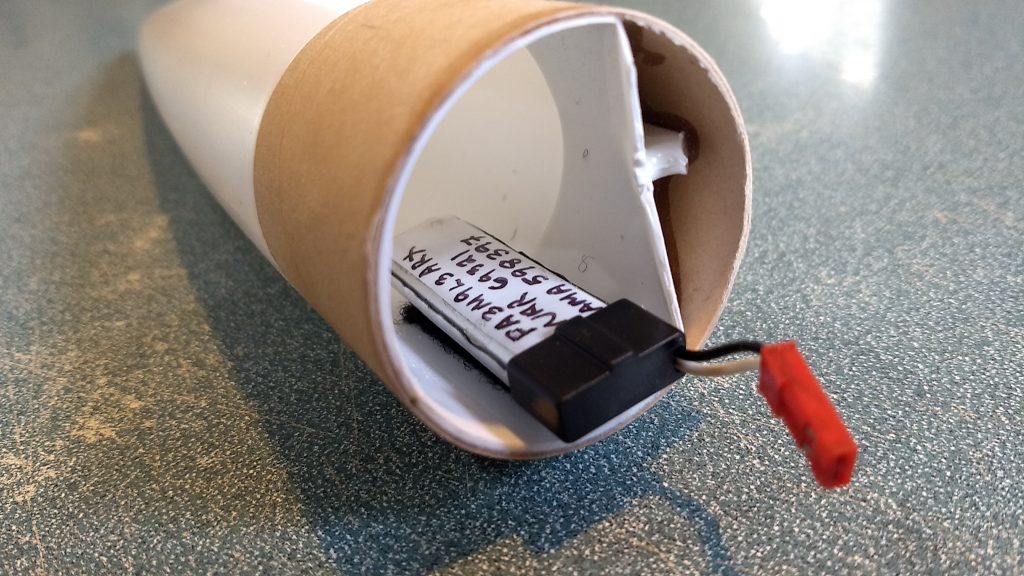
- Mount the battery with velcro inside the nose cone as far as the battery wire will reach.
-
- Slight down trim for boost.
-
- Neutral controls
-
- Up trim for glide
-
- Up elevator
-
- down elevator
-
- right aileron
-
- left aileron
-
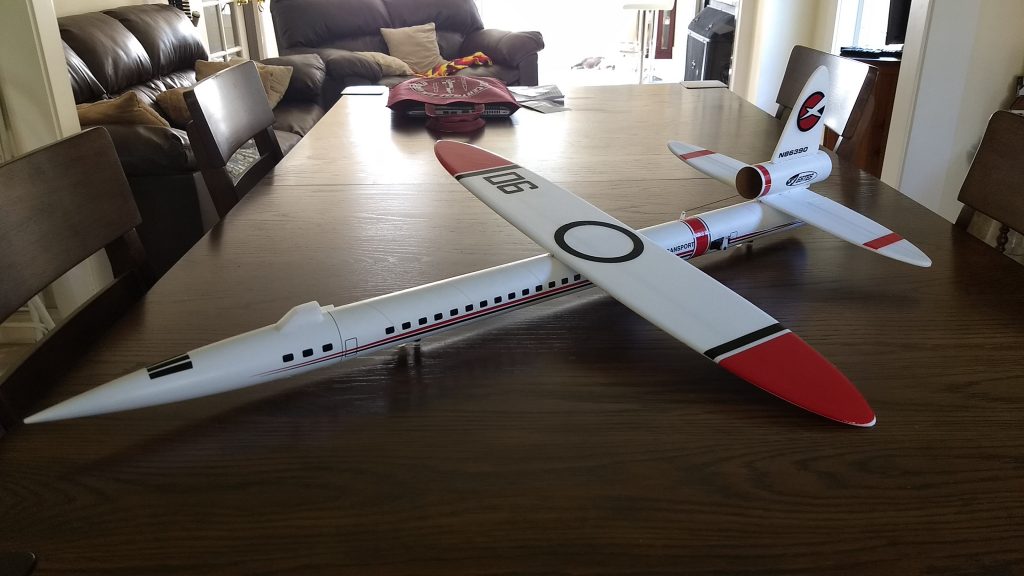
- Completed model shown with stickershock markings.
-
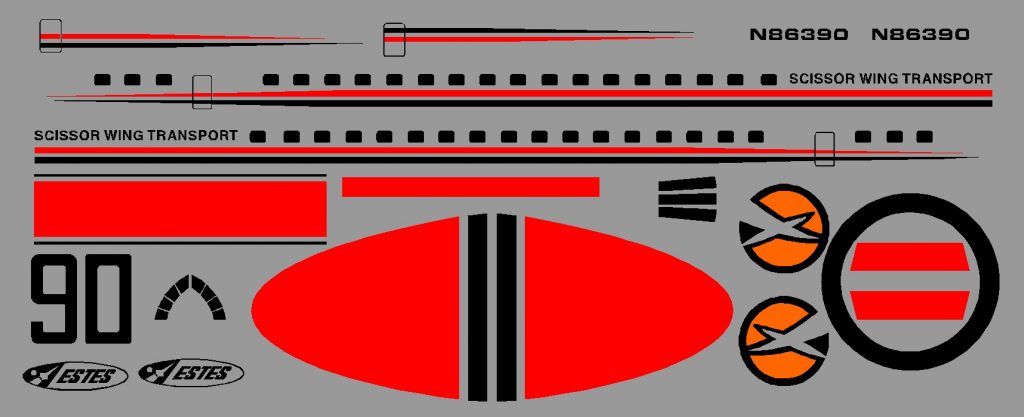
- Example of optional stickershock decals