 Interceptor 24mm kit
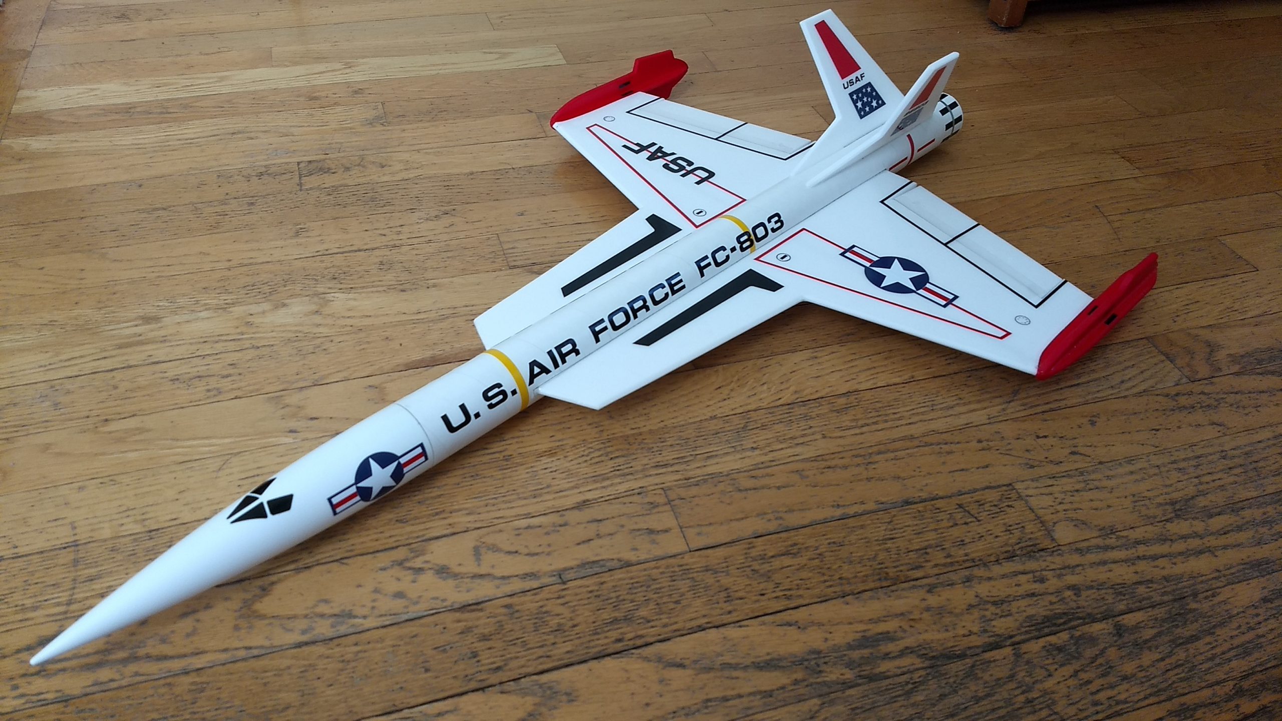
The Interceptor 24mm kit has a classic space fighter design with twin V tails, wing tip pods and sleek styling. The kit includes white 2″ body tubes, coupler, marking Guide, 6mm depron wing and tail surfaces with pre-hinged elevons, plastic nose cone, motor tube, spar, rail buttons, battery wire, velcro, blenderm tape, pushrods, motor tube, control horns and lead weight. Specs: 38″ length, 22″ wingspan, 10 oz rtf, for 24mm E-6 reloadable or single use composite motors. You will need two 10 gram type servos, two 12″-18″ servo extensions, a receiver, and a small 500mah single cell lipo battery. You will need a transmitter with delta or elevon mixing.
Kit specs: 38″ long, 22″ wingspan, 10 oz ready to fly for Composite reloadable or single use E-6 rocket motors only.
Please refer to the general instructions tab above then read the instructions completely before starting assembly. The assembly photos are for general reference but may not include every step in the instructions. High quality cut vinyl decals are available HERE select the Standard 24mm set
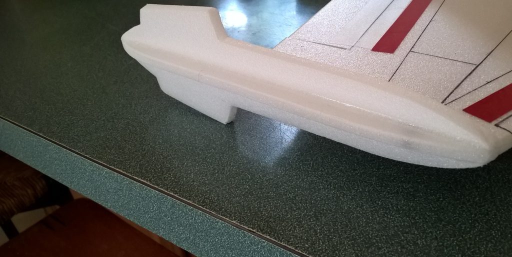
CG location for rocket flight: Where the wing leading edge meets the strake, balanced with loaded rocket motor and battery in place as ready for flight.
Welcome to the world of rocket boosted radio control gliders. This is not a model for a novice RC pilot, but anyone who is comfortable with RC flying of a medium speed model should be fine. Read through the instructions, look at the photos and be sure you understand the step before commiting to cutting or glue.
The kit contains:
2 body tubes
1 Nose cone
1 coupler
1 wing taped together
1 wing spar(carbon fiber)
2 pushrods/w control horns
2 vertical stabilizers
4 wingtip plates
Marking Guide
Motor mount
Motor block
Velcro(for battery and rx/bec attachment)\
Rail buttons with t nuts/screws(may be pre-installed)
3M blenderm tape
Lead weight
Spare depron
Notes before starting:
Reference to CA+ means foam safe CA+, normal CA+ will melt the foam! Normally you need to use accelerator to get the CA to set on the foam since there is nothing for it to soak into and activate.
I beveled the edges of the wing, strake and stabilizer leading and trailing edges with an exacto knife and straight edge, just a small 1/16″ bevel on both sides. If you decide to sand the edges instead, be very careful and use a light touch, it is very easy to catch the foam on the edge of the paper and tear the foam. Do any sanding before assembly.
Epoxy is not needed in this model. Weight is critical and the model is designed for the thrust and flight loads. Weight in the rear end is bad and will require additional weight in the front of the model.
Assembly:
- Join the two body tubes and coupler together using any adhesive.
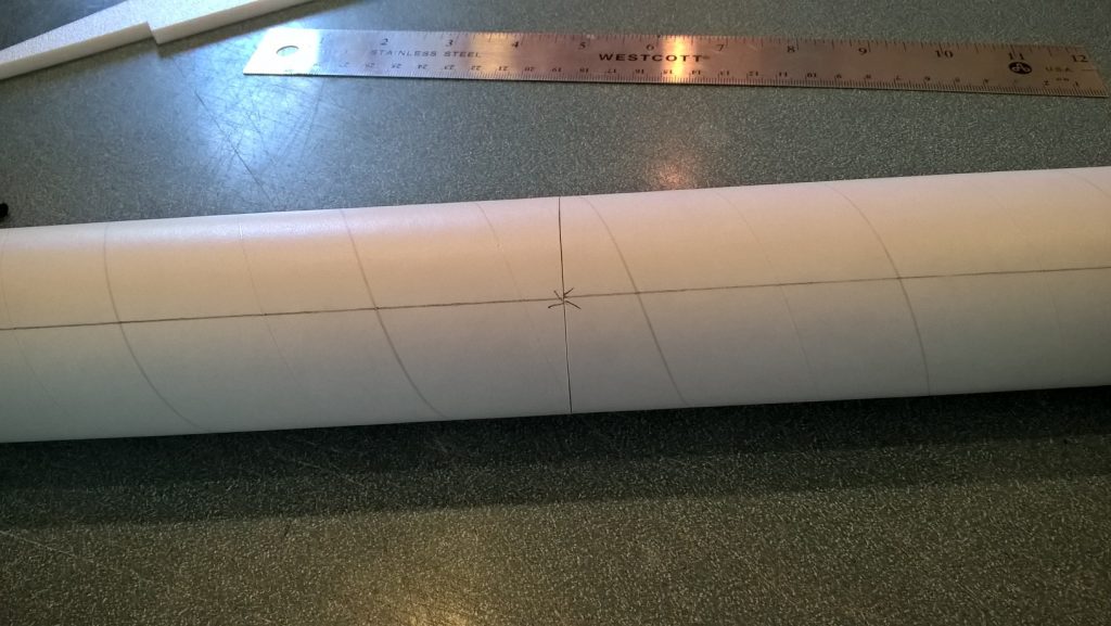
- Use the provided marking guide to mark the wing lines and upper stab lines after aligning the bottom mark on the guide with the pre-cut rail button holes.
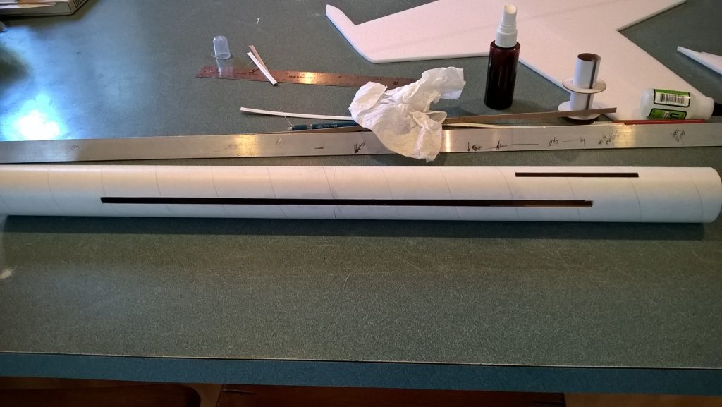
- The slots for the stabs will start 2.75″ from the rear of the body tube forward the length of the tab on the fin, use the fin to determine the length, the width will be cut to just fit the foam, take your time and make multiple passes till you cut through, test fit and adjust as needed. I use a piece of angle aluminum to cut the lines.
- The slots for the wings will start 5.5″ from the rear of the tube forward to the length of the wing, use your wing to measure the exact length and the width will be the width of the foam. Take your time and make multiple passes till you cut through, test fit and adjust as needed.
- Install the rail buttons using the T nuts. Don’t tighten down really hard, just enough to secure them.
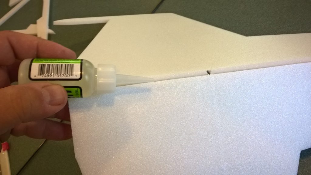
- Unfold the wing and glue it using CA+ at the taped joint, make sure it is flat.
- Glue the spar into the slot in the bottom of the wing using CA+ then tape over using the blenderm tape.
- Test fit the wing into the slot carefully. Sand or trim as needed for a good fit without dragging/damaging the foam. You’ll need to start by putting the wingtip into the slot, then rotating so that the wing goes in straight. Sand the front or back of the wing slightly if you are having trouble getting it in the slot. Make sure the wing is centered in the body tube and glue using CA+ along the top and bottom on both sides. use CA+ and accellerator.
- Install the two vertical tails. Sand the slots or tabs slightly if needed so that they fit. Glue in place with CA+ and add a light fillet. The angle isn’t super critical as long as they are symmetric.
- Glue a pushrod/control horn into the pre made holes in the bottom of each control surface, with the pushrod on the side closest to the body tube. Use CA+ and make sure it is glued well. Once done, flip the model over and put some CA+ on the top where the prongs stick through the surface to lock it in place.
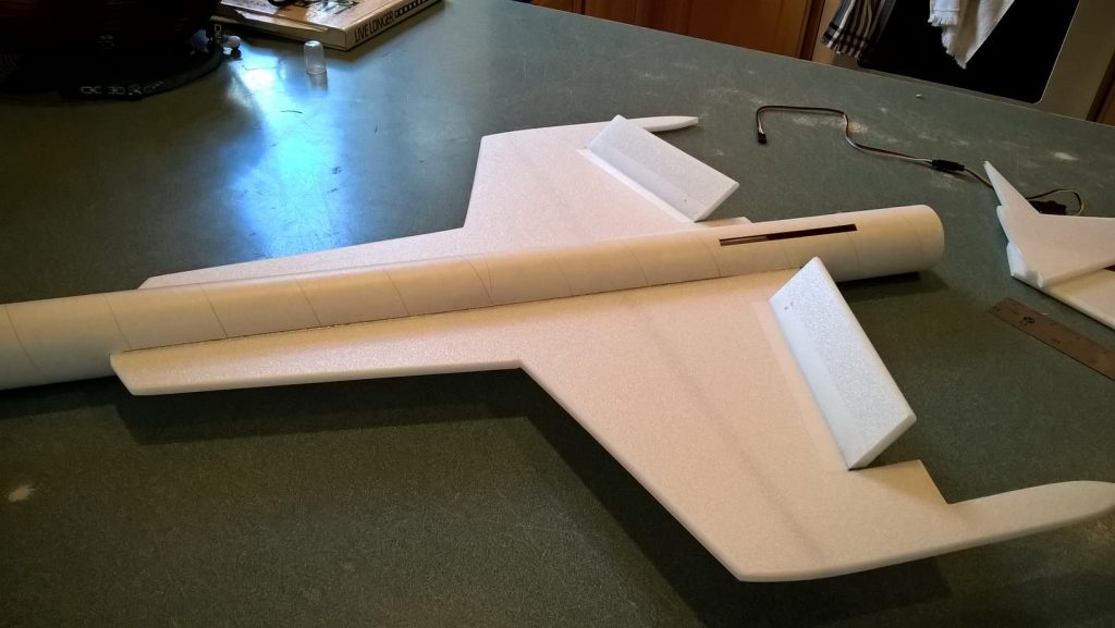
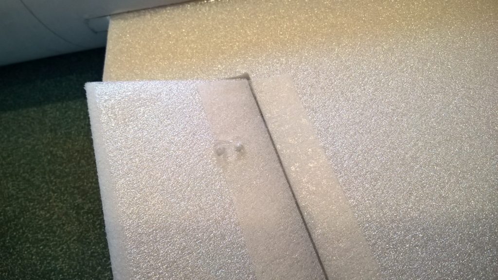
- Glue a wingtip pod on the top and bottom of each wingtip using CA+. Make sure they are straight front to back and are straight up and down. Sand lightly if needed. Make sure the wing stays flat and isn’t twisted when you glue them in place. These help stiffen the wing tips.
- Glue the four foam strips onto the motor mount on the lines marked. If using single use motors you may glue the motor block to one end of the mount, if you are using reloads, the rear ring will stop the casing from moving forward and you do not need this ring, it allows the motor to be more forward which helps CG.
- Test fit the motor tube into the body tube, it will be rotated so the tabs are at 45 degrees to the wing and will clear the rear rail button. Sand the tabs lightly till it will fit. If the mount is a loose fit, simply slice some thin foam slices from the spare foam included and glue them to the edges of each tab then sand to fit. Glue in the motor mount into the tail inset 1/2″ to 3/4″ Make sure the thrust ring is forward if you used it!
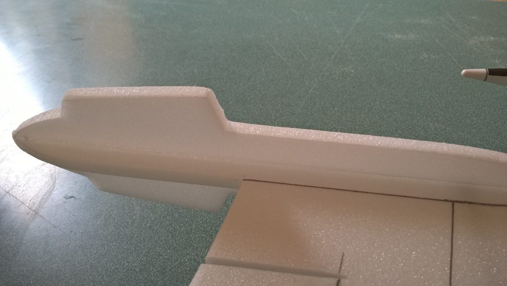
The basic construction is now complete.
Radio Installation
Note: Your radio needs to be configured for Delta mixing, this means that the servo arms will move the same direction during elevator stick movement and opposite for aileron stick movement. Connect your servos to the receiver one in the aileron connection and one on the elevator connection and apply power. Use a servo arm at least 9/16” long and with holes small enough that there won’t be slop with the pushrod wire when installed. I use the hole furthest out on the servo arm, to maximize movement. On some servos there are a long two-ended servo arm, you can trim off one end if needed to get sufficient length. Zero out any trim settings on the transmitter. The model once the motor has burned out is nose heavy and flying wings lose pitch authority when nose heavy so you want as much up elevator travel for trim/flare as possible.
- Connect a servo to each pushrod, the servo wire should be closest to the center and the output shaft is outboard toward the wing tip. If the wire is too tight, you can use twist an exacto knife in the servo arm hole to make it larger, but be careful and do not make it too large. Once connected, tape each servo in place so that the control surfaces are centered. Flip the model right side up and look at it from the rear. Moving the transmitter stick back(up elevator) should move both elevons up. Moving the transmitter stick to the right should move the right elevon up and the left elevon down. If you can’t get the servo reversing to give you the right polarity try swapping aileron/elevator inputs to the receiver or turning the servos over and swapping the servo arms to the other side of the output shaft. If that is correct, continue.
- Mark the body tube where the servos will be when the control surfaces are level, I tape the control surfaces flat for this step. Cut pockets in the body tube/coupler as needed to inset the servos slightly.
- Connect your servo extensions that are long enough to get to the front of the body tube, then route the servo wires forward through the pockets and connect them back to the receiver and power up the radio again.
- With the radio still on, put a small amount of glue on the servo, being careful not to get any near the output shaft. And set it in place in the pocket keeping the control surface centered. Do the same to the other side. Make sure the glue is set before continuing. Remove the tape holding the surfaces.
- Flip the model back right side up. Make sure the control surfaces are centered, use trims if needed. Now measure the control surface movement. Full elevator movement should be 1” in each direction, aileron movement should be 1/2″ in either direction. Since the model will be nose heavy, extra elevon movement helps to give sufficient authority during glide.
- If you have a flap/elevator mix you can program up elevator to a switch setting. The model needs approximately 1/4” of up elevon during glide and slightly less than1/8″ of down trim for boost. If you can’t set the up elevator trim to a switch on your radio you’ll have to manually put in boost and glide trim which is hard to do while flying the model.
- Use the included Velcro to attach the receiver 2″ from the front of the body tube on the top(or enough to allow the wires to clear the shoulder of the nose cone). This allows you to be able to remove and replace the receiver if needed for repairs or for removing the servo wires. I attached the battery inside nose cone on the shoulder.
- I used markings from stickershock. With the vinyl from stickershock23 it helps once applied to use a hair dryer on hot to soften the material and then push it down onto the model with a towel. It helps it conform and stick much better. I put a 1.5-2″ wide strip of clear tape on the bottom of the body tube, this helps keep the body tube from getting dirty/wet on landing.
- Use a black sharpie to add panel lines if desired, I ran a fine line sharpie into all the panel lines in the nose cone and it really sets it off. You can use red wide sharpie for the wingtips or see the general instruction page for notes on painting.
- Insert your heaviest loaded rocket motor into the motor mount.
- Support the model upside down at the balance point indicated for boost. I use two chopsticks with little foam squares on the points held in place with a small hand vice. Place the model upside down on the pencil erasers on the balance point indicated in the kit spec sheet. Adjust the location of your flight battery to achieve balance and use the included velcro to hold it in place. If needed, use the some of the included lead weight to balance it either in the nose or tail as needed. Do not try to fly the model with it balancing it behind this point. The adage is, a nose heavy model flies poorly, a tail heavy model flies once
Flying: See the Instruction/Information link at the top for flying instructions Note, my prototype needed a small amount of down trim on boost and as it gained speed arced back up vertical. Be ready on the first few flights to keep the model straight till you have the trims set perfectly for boost and glide.
-
- Glue the two body tubes together
-
- Cut the wing and tail slots
-
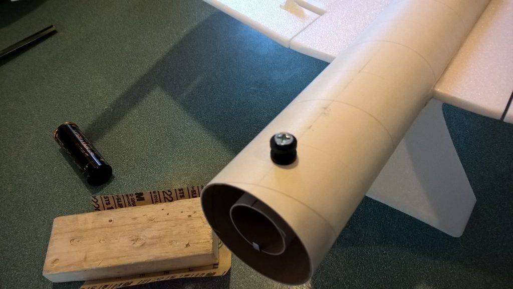
- Install the front and rear rail buttons
-
- Glue the wing at the taped joint
-
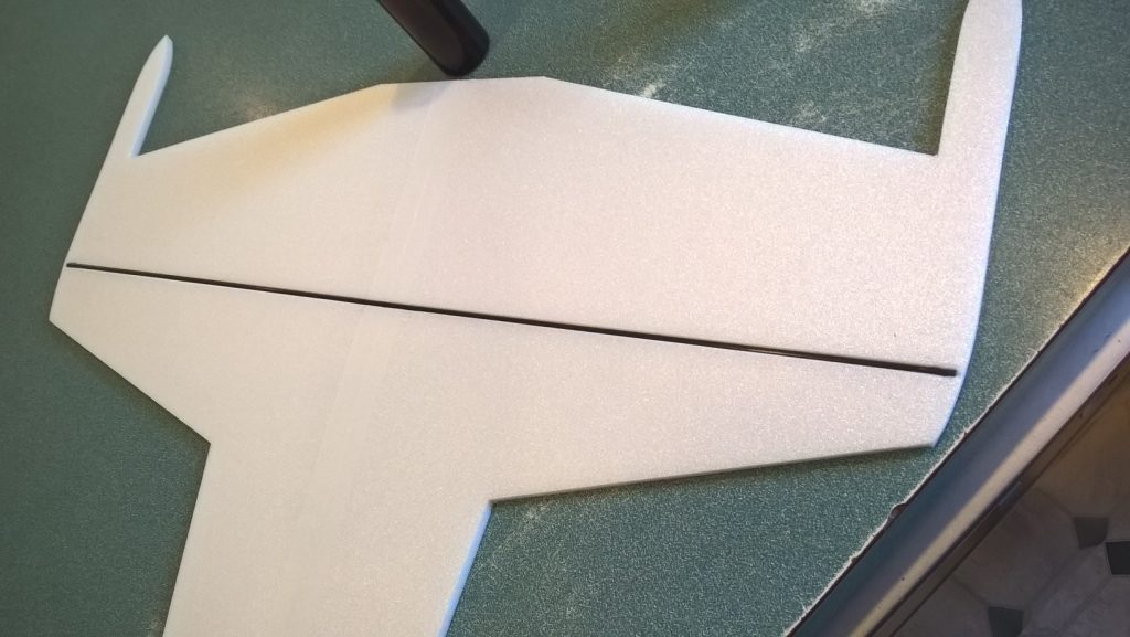
- glue in the spar and tape over the spar
-
- slide the wing into place and glue when centered
-
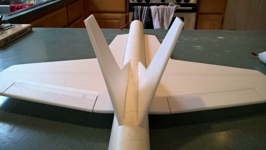
- Glue both vertical stabs in place.
-
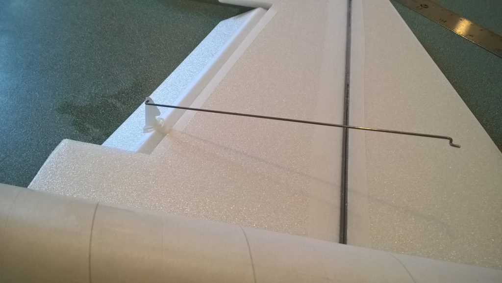
- Glue a pushrod/control horn on the bottom of each control surface
-
- Apply glue to the control horn prongs to lock them in place
-
- Glue the wing tip plates on each wing tip top and bottom
-
- wing tips installed
-
- If not assembled for you, glue the four foam tabs onto the motor tube, evenly spaced and even with the front of the motor tube. If included glue the thrust ring to the front of the motor mount.
-
- Test fitting motor mount
-
- recess the motor mount 1/2″ into the rear of the model and glue in place.
-
- Servo notches cut and servos inset into the body tube and glued in place.
-
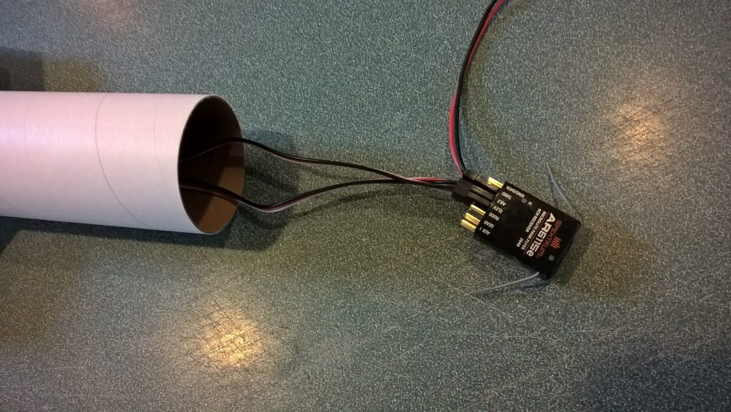
- connect the servo wires to the receiver, then velcro receiver inside the body tube about 2″ in.
-
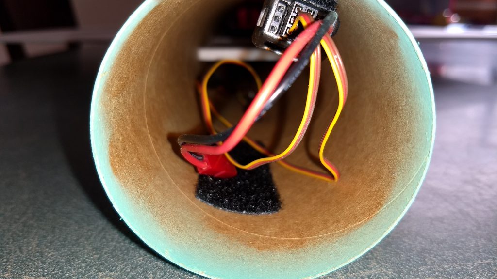
- Receiver mounted inside the body tube with velcro, battery secured with velcro in nose cone or body tube as required for balance.
-
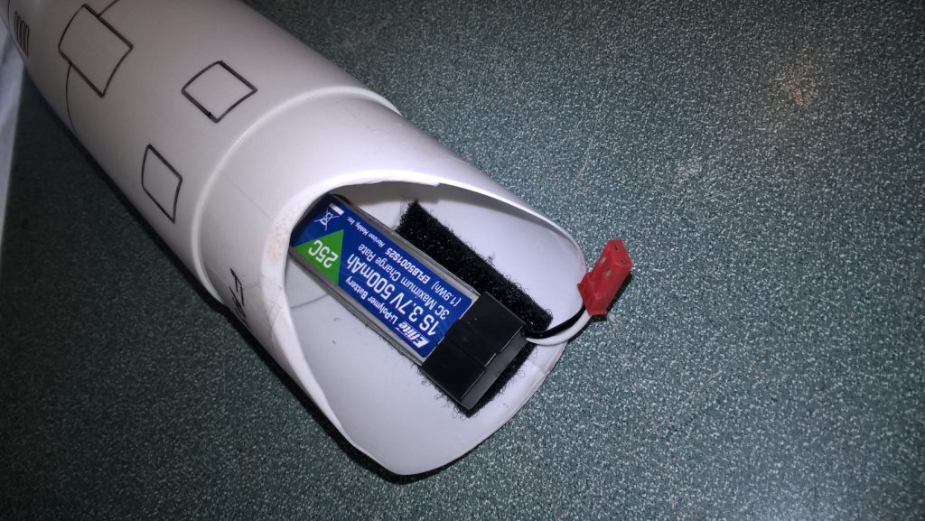
- velcro the battery to the inside of the nose cone or body tube as required for balance.
-
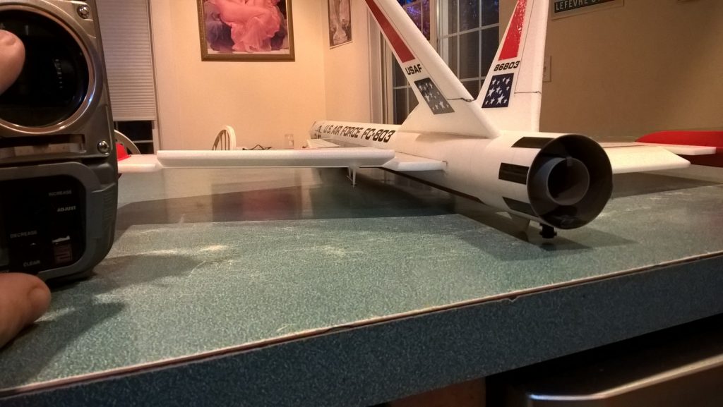
- slight down trim for boost
-
- glide trim
-
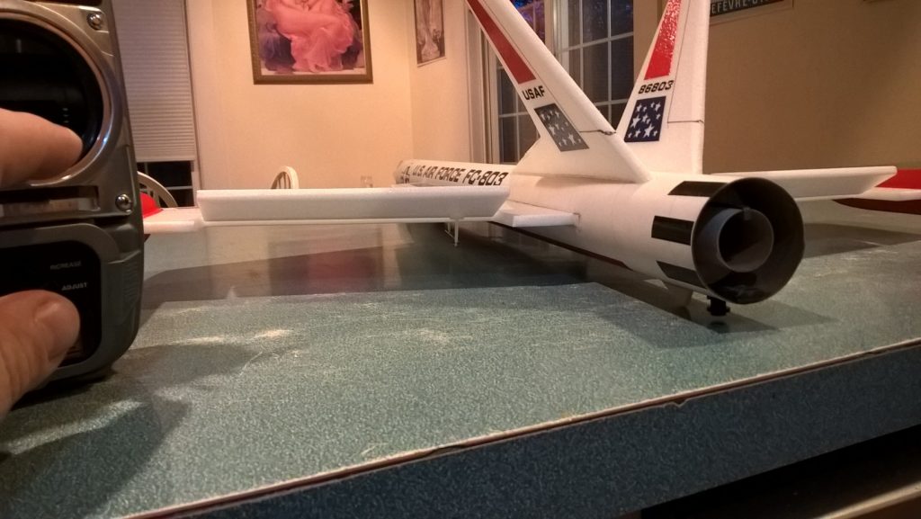
- up elevator
-
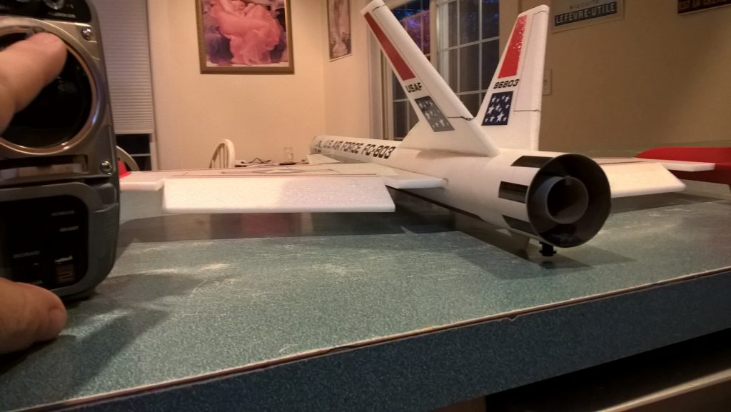
- down elevator
-
- left aileron
-
- right aileron
-
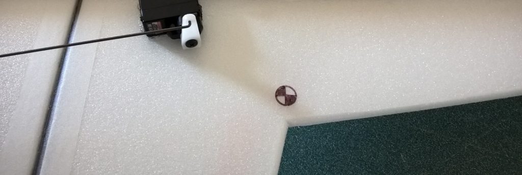
- CG location at wing/strake intersection
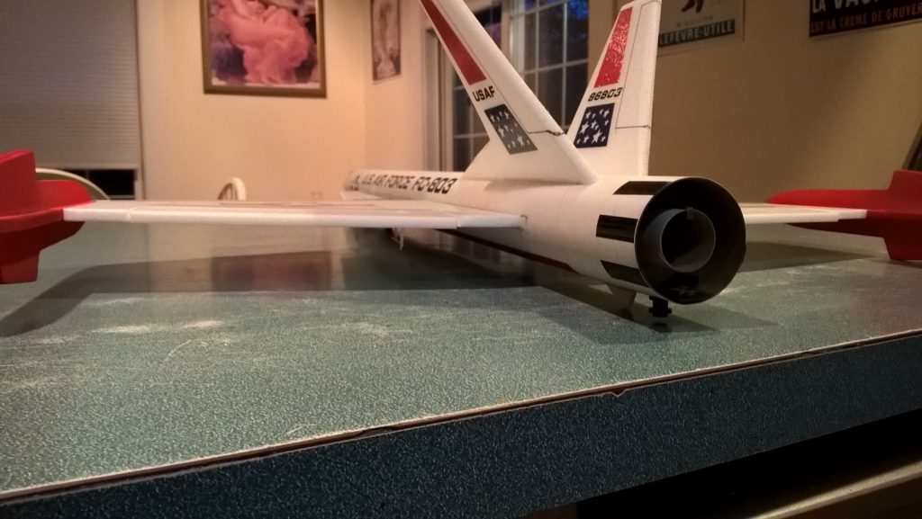
-

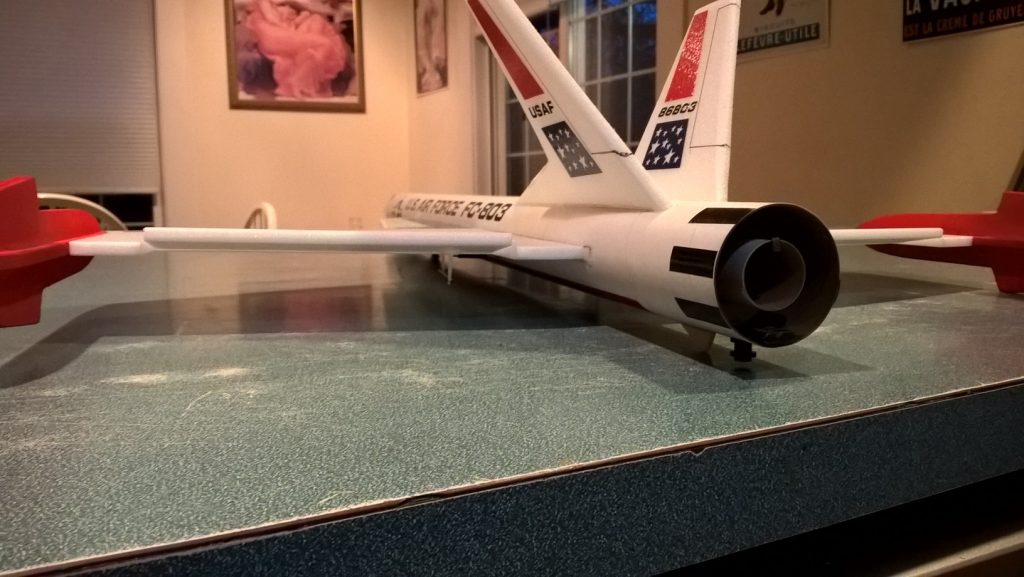
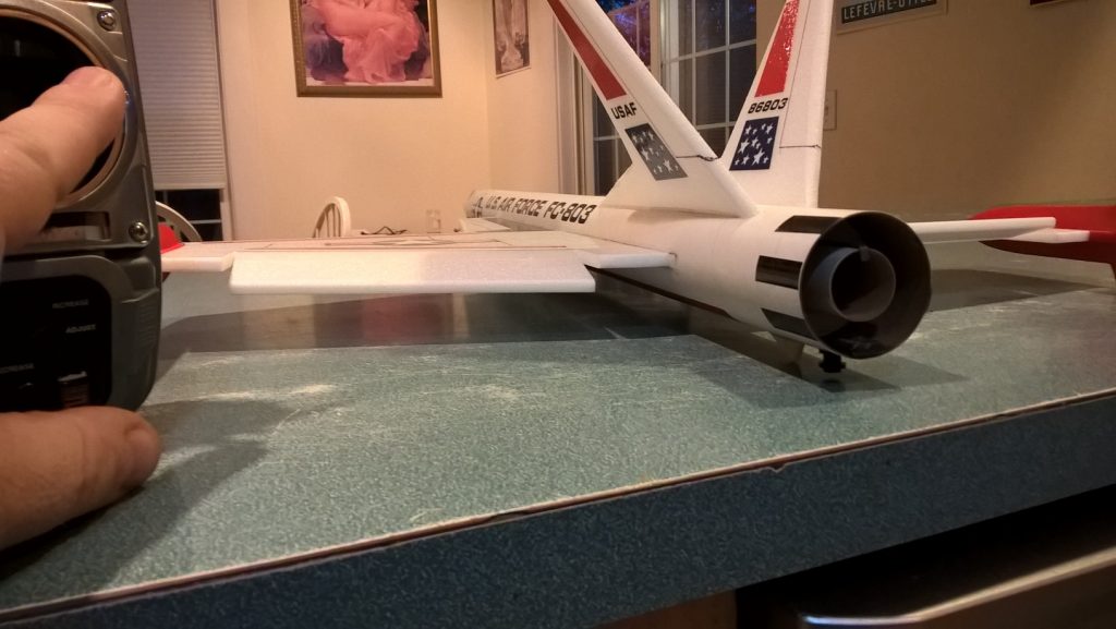
- Completed Model