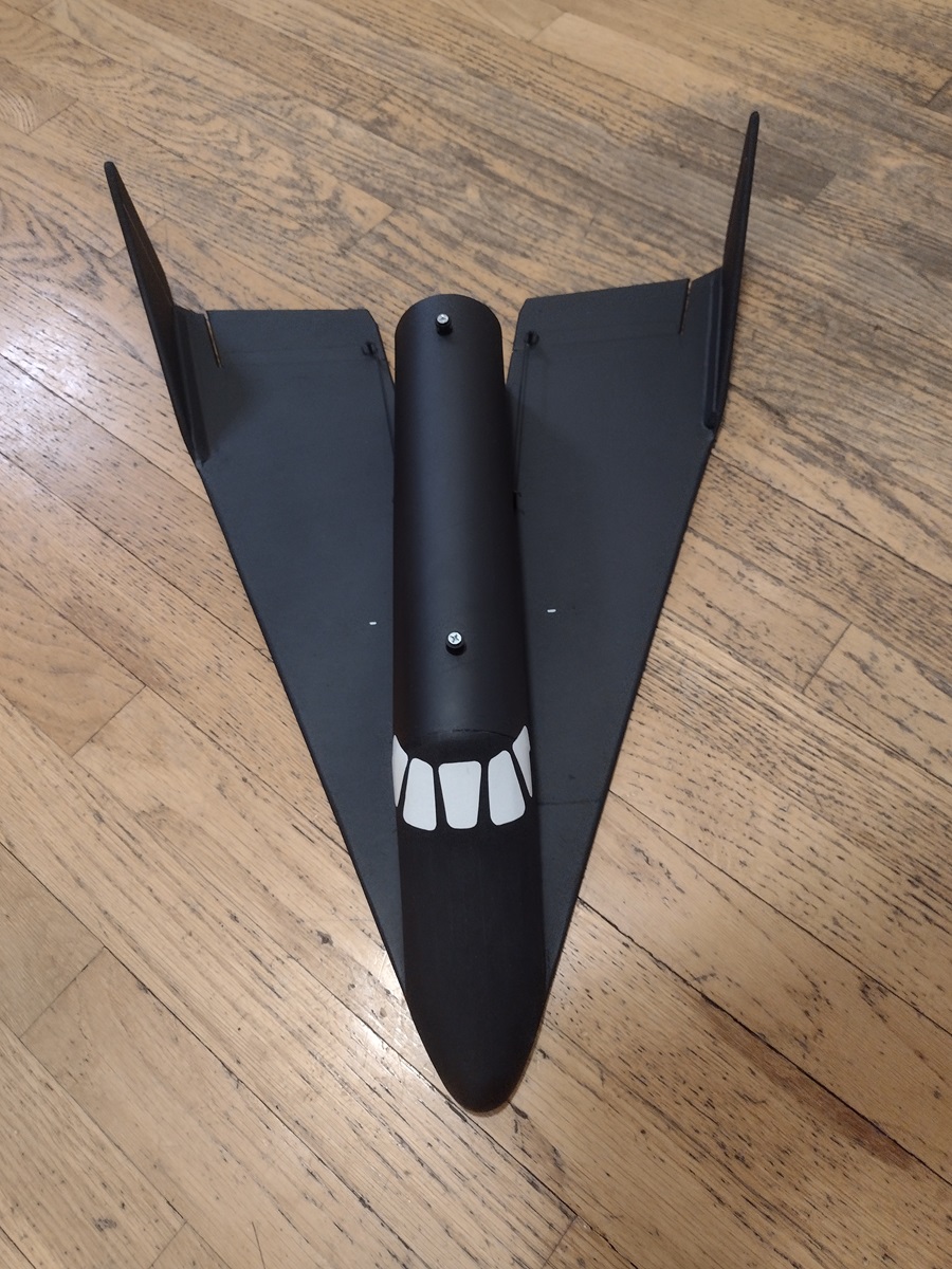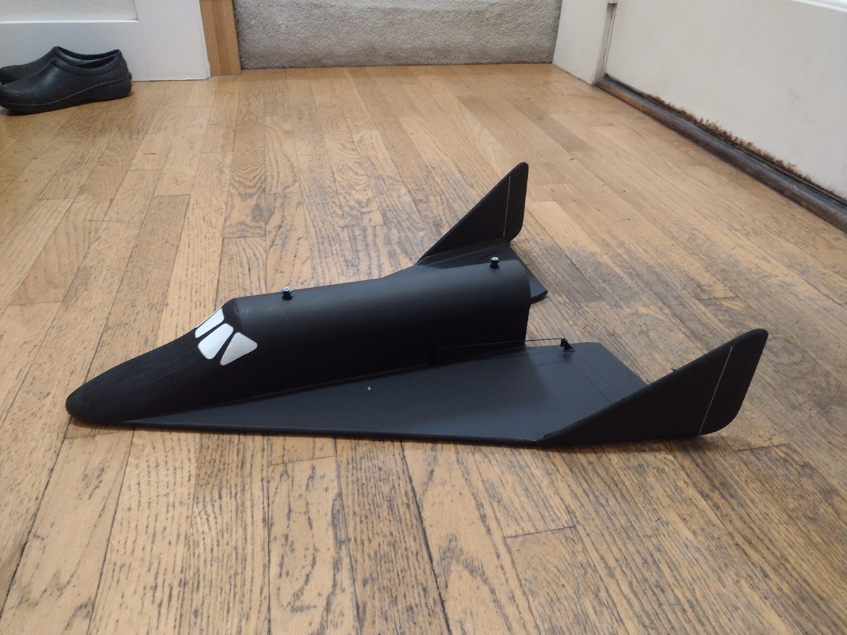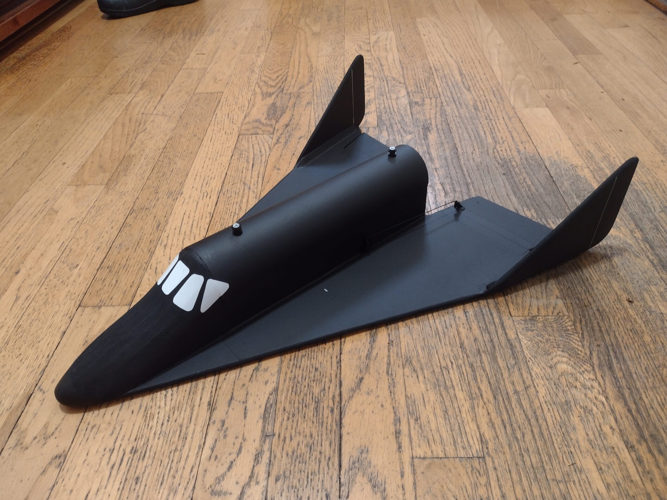
24mm 1:18 scale Dyna-Soar sub-orbital Rocketplane kit.
The 24mm Dyna-Soar Rocketplane kit is for advanced builders and flyers. This was a USAF proposal for a manned manouverable winged re-entry vehicle. It models the early sub orbital version that was to be mounted on top of a Titan II rocket for suborbital flight testing without the rear body flare. It comes with pre-cut 6MM Depron wing, former and tail surfaces, 3mm body sides and BT-80 Fuselage top . The elevons are pre-hinged and spar slot is pre-grooved. Rail button holes are pre-punched and the kit comes with rail buttons. You will need two 8-11 gram type servos, a receiver, and a small 500mah single cell lipo battery. You will need a transmitter with delta or elevon mixing. Foam safe CA+ is the only correct glue to use for all construction on this model except for 3m-77 fir laminating the nose piecesn. Any other adhesive will add weight in the wrong place, and reduce flight performance. Please refer to the General instructions for all kits tab above, then read these instructions completely before starting assembly. For 24mm composite E-6 reloadable motors only. Wingspan 16″, length 22″. Weight 8.4-8.5 oz rtf. No RFID or drone registration is needed for this kit. Kit comes with white vinyl to cut your own cockpit decals, nothing else is needed for markings.
CG location for rocket flight: 7″ forward of the rear of the fuselage with battery and motor installed ready for flight.
Welcome to the world of rocket boosted radio control gliders. This is not a model for a novice RC pilot, but anyone who is comfortable with RC flying of an aileron controlled medium speed model should be fine. Read through the instructions, look at the photos and be sure you understand the step before commiting to cutting or glue.
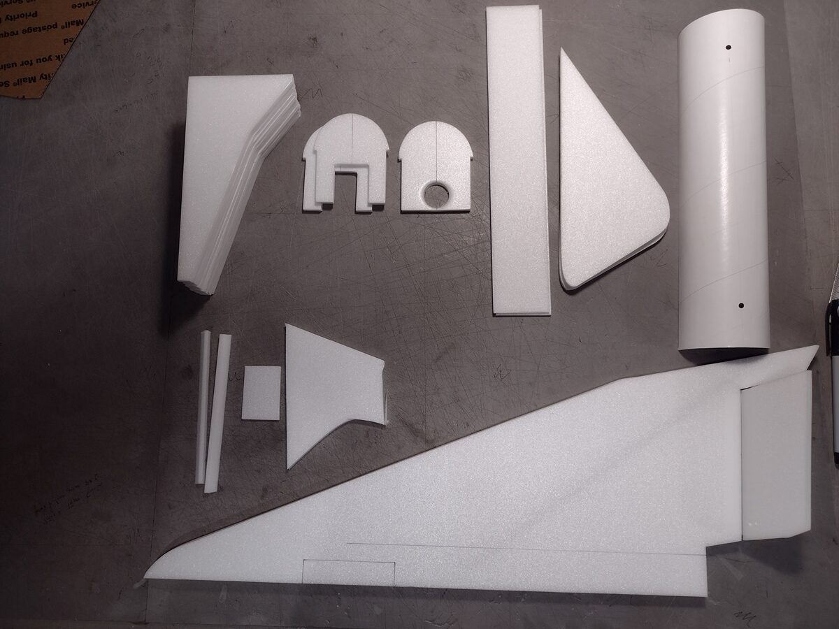
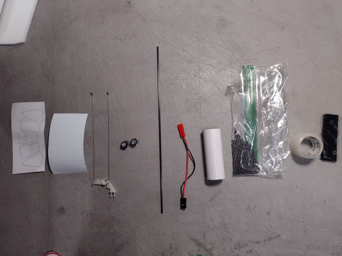
Identify all pieces, the kit should contain:
1 6mm wing taped together
2 6mm vertical stabilizers
2 6mm gussets
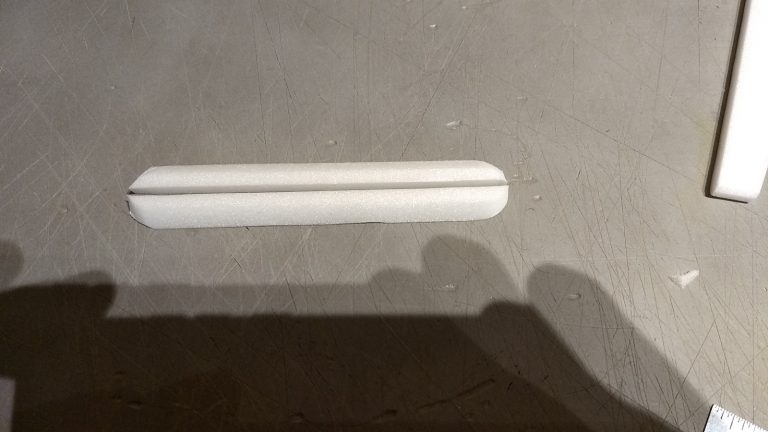
1 3mm hatch lip
2 3mm side plates
3 6mm formers
1 BT-80 body tube top with holes for rail buttons
2 control horns w/pushrods
Velcro(for battery and rx/bec attachment)
3M blenderm tape
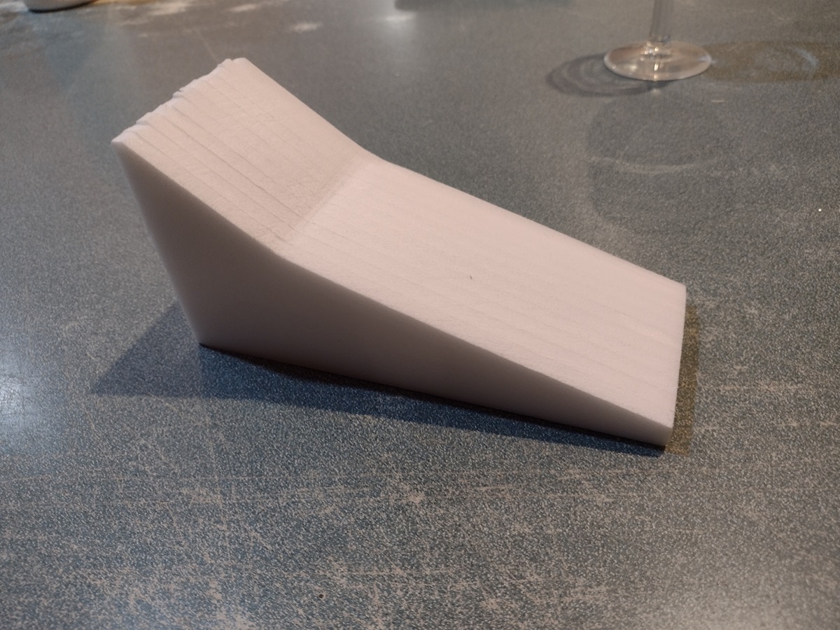
11 6mm Nose sections.
1 24mm motor tube
1 carbon spar
2 rail buttons/t-nuts and screws
Cockpit decal template and white vinyl
Lead weight
spare depron for repairs or paint testing.
Assembly:
- Look at all parts and understand what pieces go where.
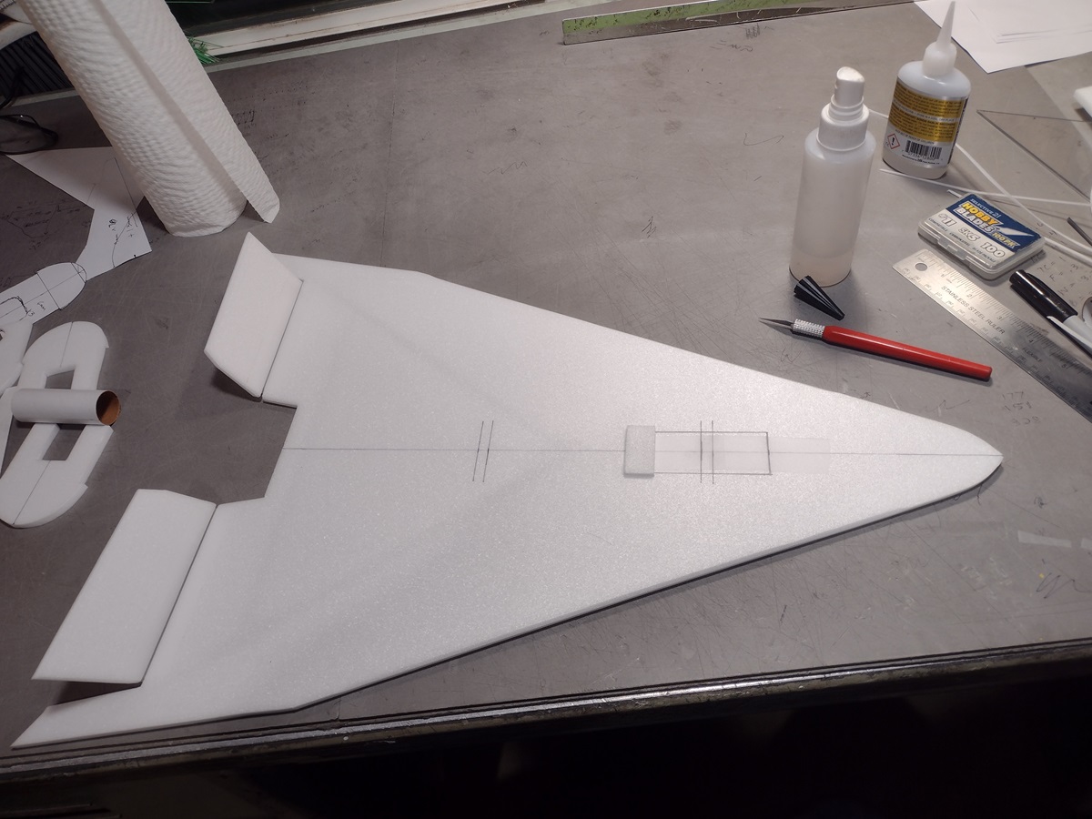
- Unfold the main wing and glue the taped joint.
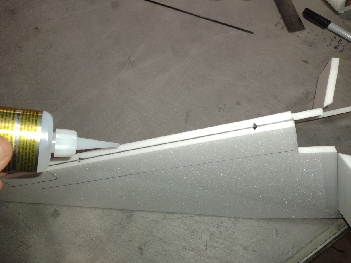
- Glue in the spar into the premade slot on the bottom of the wing and then tape over with blenderm tape.
- Sand the leading edge of the wing and trailing edge of the elevons rounded. ** Do not round the top front 3-4″ of wing as the nose will glue there**
- Round the stabilizer top and rear edges only, do not round the bottom edge which will glue to the wing** this will be done after installing it.
- Cut out hatch and hinge the hatch at the front both inside and outside using blenderm tape. Tape the outside using a 2″ long strip, then use a 3″ strip on the inside wrapping over the hatch door, and around over inside of the wing.
- Make a tape handle on the other end of the hatch using a 2″ long strip, starting on the outside, overlapping the tape on itself about 1/4″ and then wrapping the tape around the end of the hatch door and inside the hatch door.
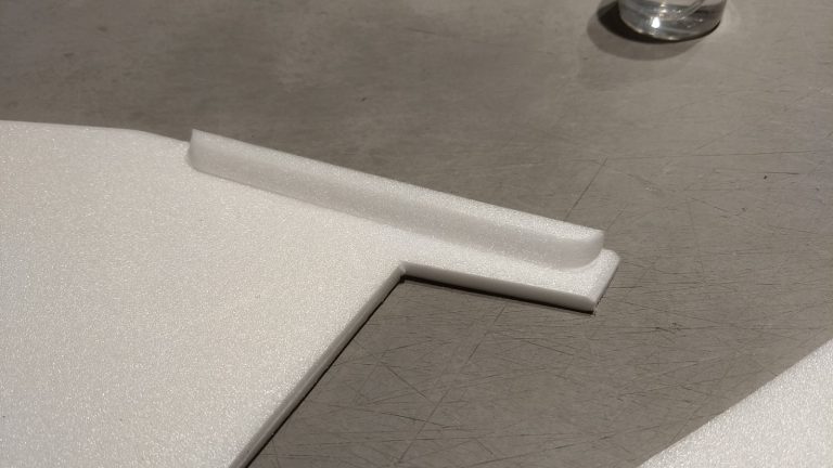
- Glue the 3mm hatch lip on the inside of the fuse, overlapping the hatch opening about 1/4″ to make a little lip so the hatch won’t go in further than flush with the bottom of the wing when closed. I used a tiny bit of masking tape to hold the hatch closed for flight. DO NOT glue the lip to the hatch!
- Sand the ends of the 6mm depron angle cut gussets to a rounded shape, these will reinforce the stabilizer joint
- There are three formers, one with a round hole for the motor tube at the rear and two with openings cut to route the servo wires and access the receiver.
- Sand the hole cut into the rear former till the motor tube will just fit inside snugly.
- Using one of the 3mm side plates as a guide, keep one end of the side plate even with the rear of the wing at the center, then using the front of the side plate mark the wing. This mark will be the front of the forward former.
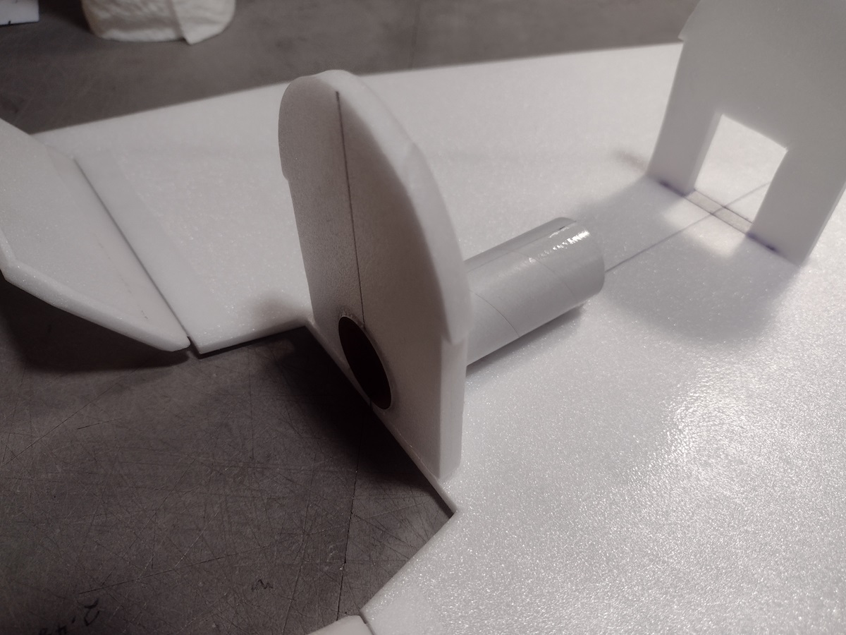
- Glue the three formers in place. The rear former is flush with the rear of the wing at the center, the middle former is about 5.5″ ahead of the rear former and the forward former goes just to the rear of the mark you made using the side plate as a guide. Do not glue the front former to the hatch. The formers should be centered left and right between the lines drawn on the wing and should be vertical, especially the front and rear formers!
- Glue in the motor tube flush with the rear of the rear former and aligned on the wing center joint at the front. It should contact the wing at the bottom, I just inserted it and then got it lined up and then ran glue under the tube and around the rear inside former joint.
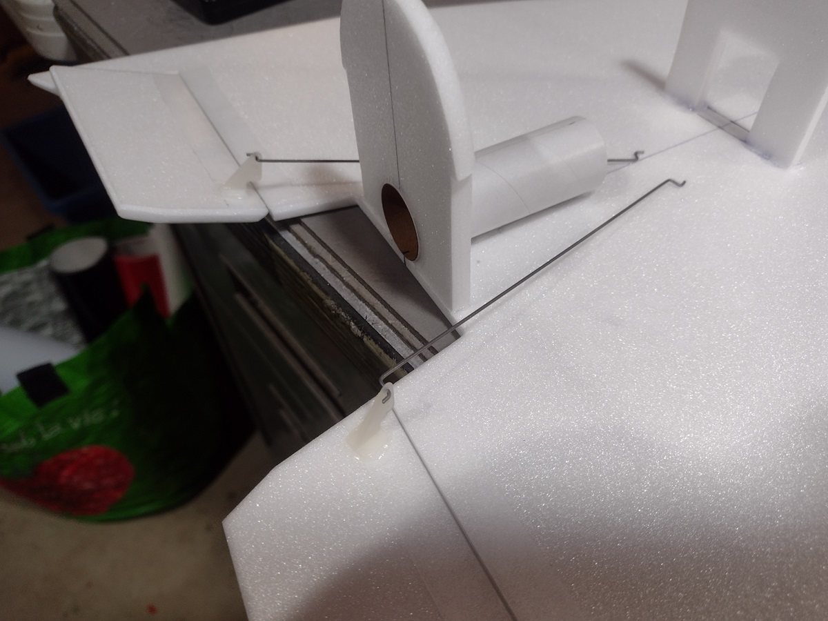
- Install the control horns in the top of each elevon, the pushrod should be closest to the body tube.
- Put a dab of glue on the control horn prongs that stick thorugh the elevon on the bottom to lock them in place.
- Test fit the two side plates in place to make sure they fit under the former notches.
- Your radio needs to be configured for Delta mixing, this means that the servo arms will move the same direction during elevator stick movement and opposite for aileron stick movement.
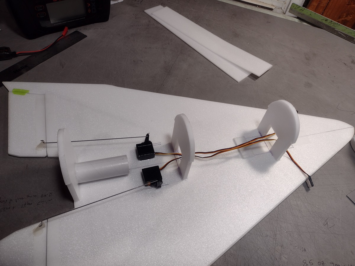
- Connect your servos to the receiver one in the aileron connection and one on the elevator connection and apply power. Use a servo arm at least 9/16” long and with holes small enough that there won’t be slop with the pushrod wire when installed. I use the hole furthest out on the servo arm, to maximize movement. On some servos there are a long two-ended servo arm, you can use this arm and trim off one end. Zero out any trim settings on the transmitter.
- The servo electrical wires should point forward.
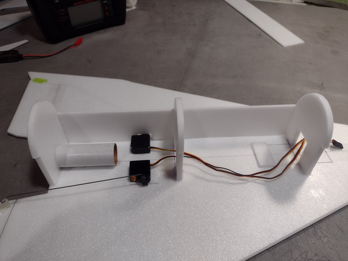
- Check that when you pull back on the elevator stick both servo arms move forward, and when you go to the right that the right servo arm goes forward and the left servo arm goes backwards. Swap servo inputs or try servo reversing till this is correct.
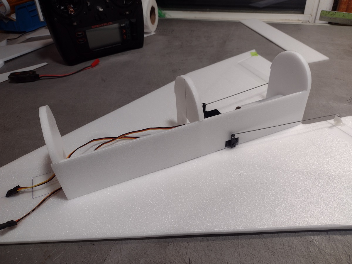
- Connect each servo to the pushrod, the pushrod should go inside the control arm so that the front of the Z bend is away from the side of the model so it won’t catch on the foam side when it moves.
- Tape the servos down temporarily to hold them in place and double check the control movement. When you pull back on the stick both elevons will go up, when you go right the right elevon will go up and the left one will go down, if this is correct continue.
- You need to glue the servos so that the servo horn is just outside the 3mm side plate when installed and the servo arm and pushrod won’t drag on it.
- If the servo wants to sit at an angle you can bend the z bend nearest the servo with a needle nose pliers to adjust so the servo is parallel with the fuselage.
- Keeping the control surface level glue each servo to the wing making sure the arm will clear the side plate when installed.
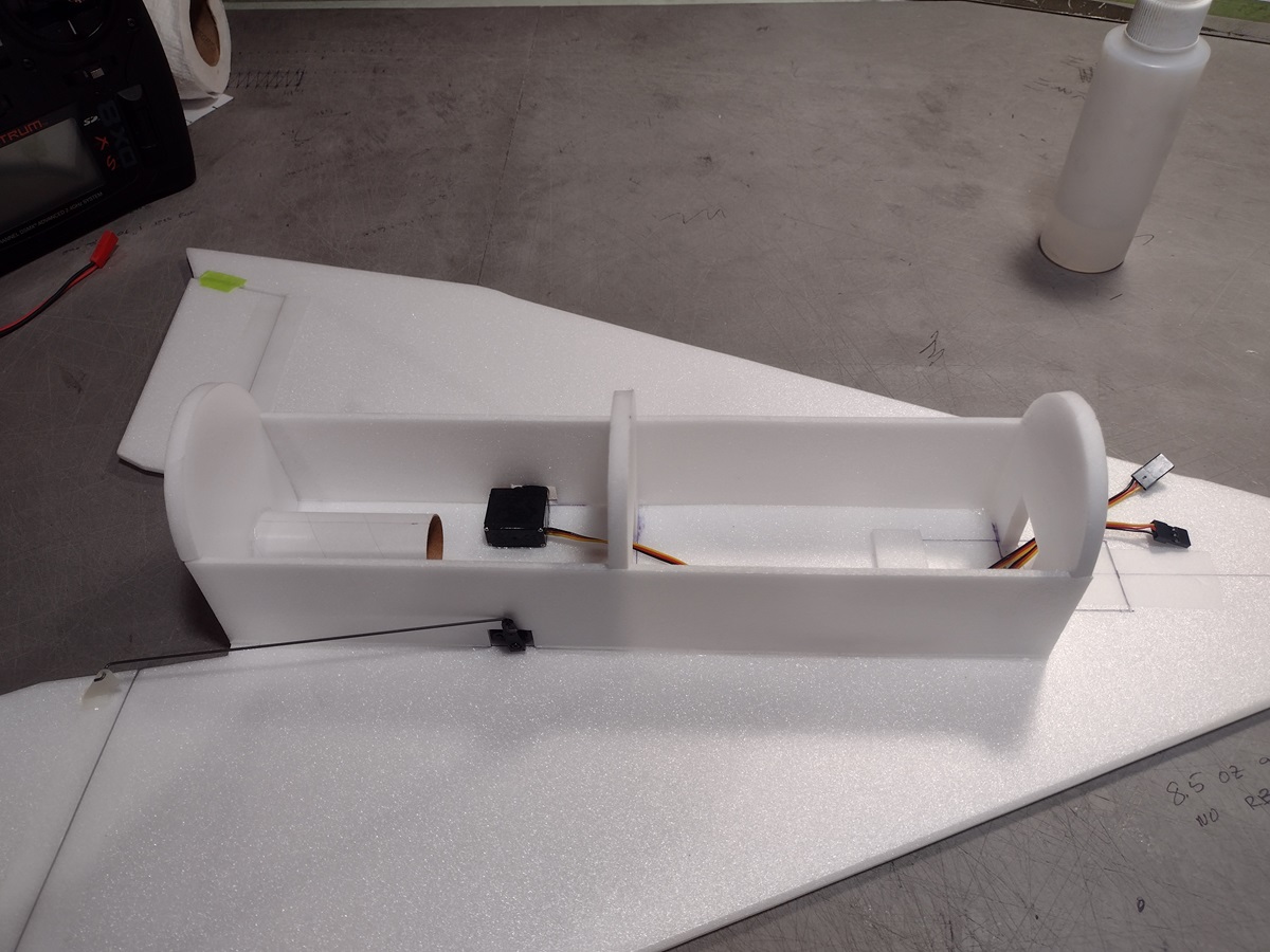
- Test fit the side plates and cut out the 3mm side plates to clear the servo and servo horn, check that the plate will fit under the former notches and clear the servo arm, glue in place to the wing and formers when satisfied. Repeat on the other side.
- Route the servo wires forward through the formers and tape the ends to the inside of the hatch temporarily.
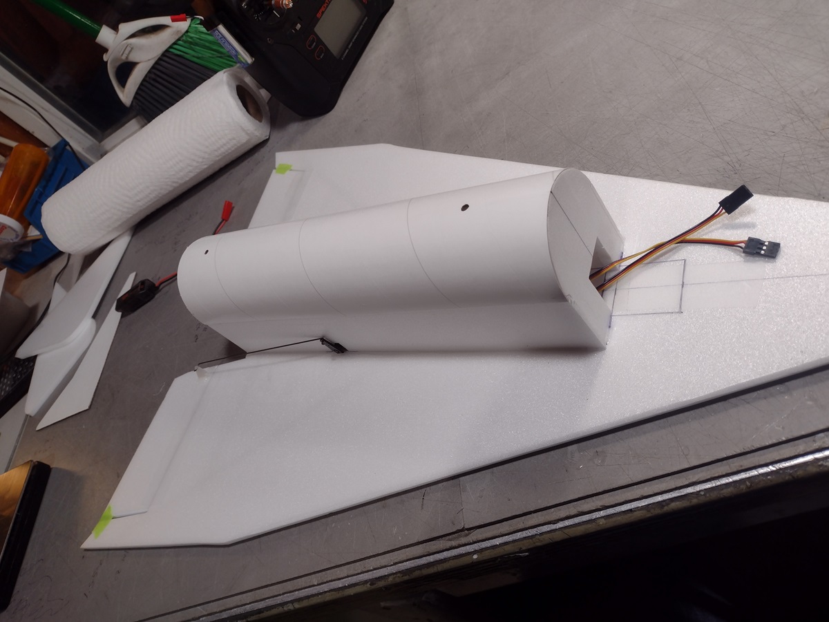
- Install the rail buttons into the fuselage top at this time. If you forget you can cut an access hole in the rear of the rear former and use a tool to hold the t nut from the inside of the body tube and attach the rail buttons on the outside. The front hole can be accessed from inside the hatch if needed.
- Test fit the body tube fuselage top, it will glue to the formers, be flush with the front and rear former and overlap the 3mm sides about 1/8″ on each side and glue to them, glue in place and make sure the glue is set before continuing.
- Glue your nose profiles together with 3m-77 spray adhesive. Spray both sides of 9 of them and the inside only of the last two.
- Take your time and carefully line up the rear and bottom of each piece and glue to the next piece keeping them aligned. These are cut by hand using a template so there is variation, once done lightly sand the bottom and rear of the assembly smooth by sanding on a piece of 220 grit paper on a table top. Do not sand an angle into the rear as you go, check against the former and wing as you sand to make sure not to over sand. Go slowly, check often.
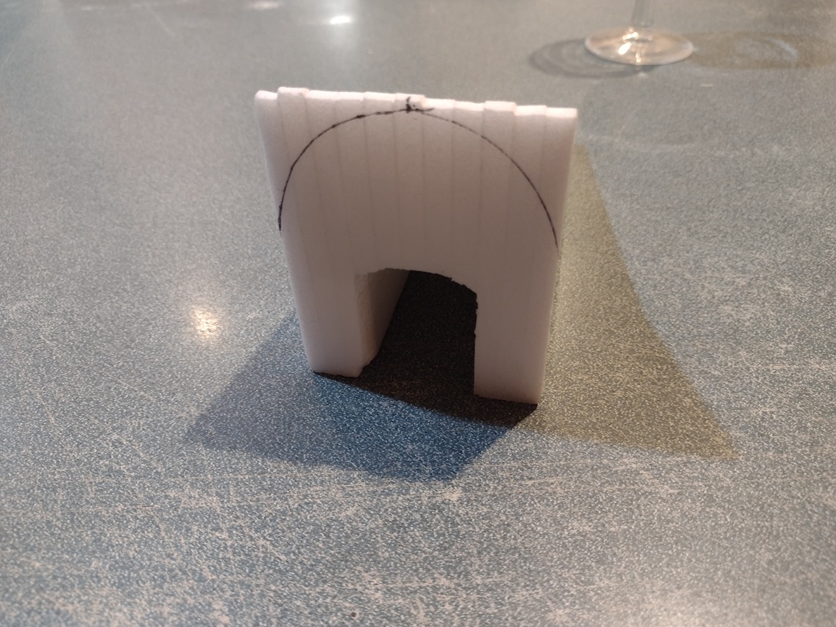
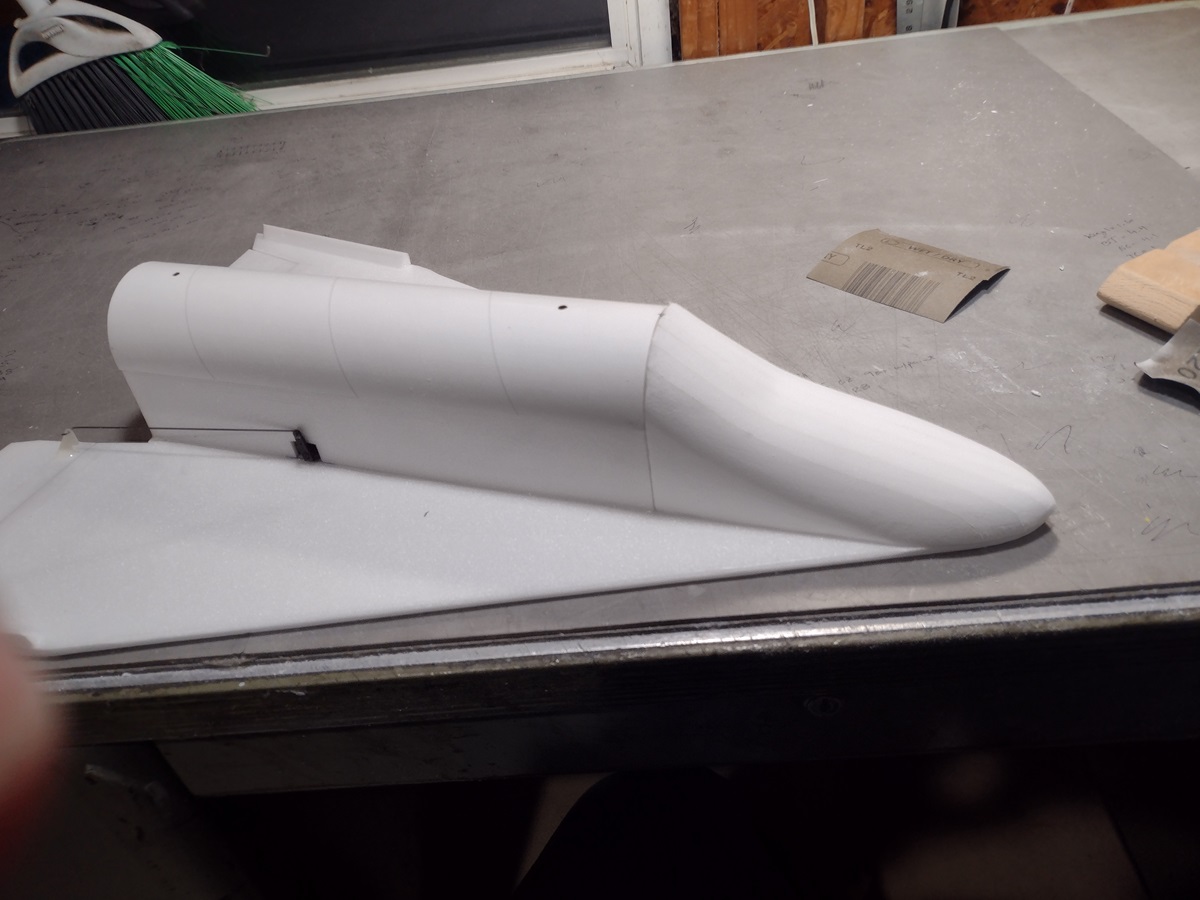
- Test fit the nose assembly on the wing and against the former, mark the wing and former on the cone and rough shape to size. I used 220 grit paper and a bread knife to do rough carving, then switched to 320, do not final sand at this time, just get close.
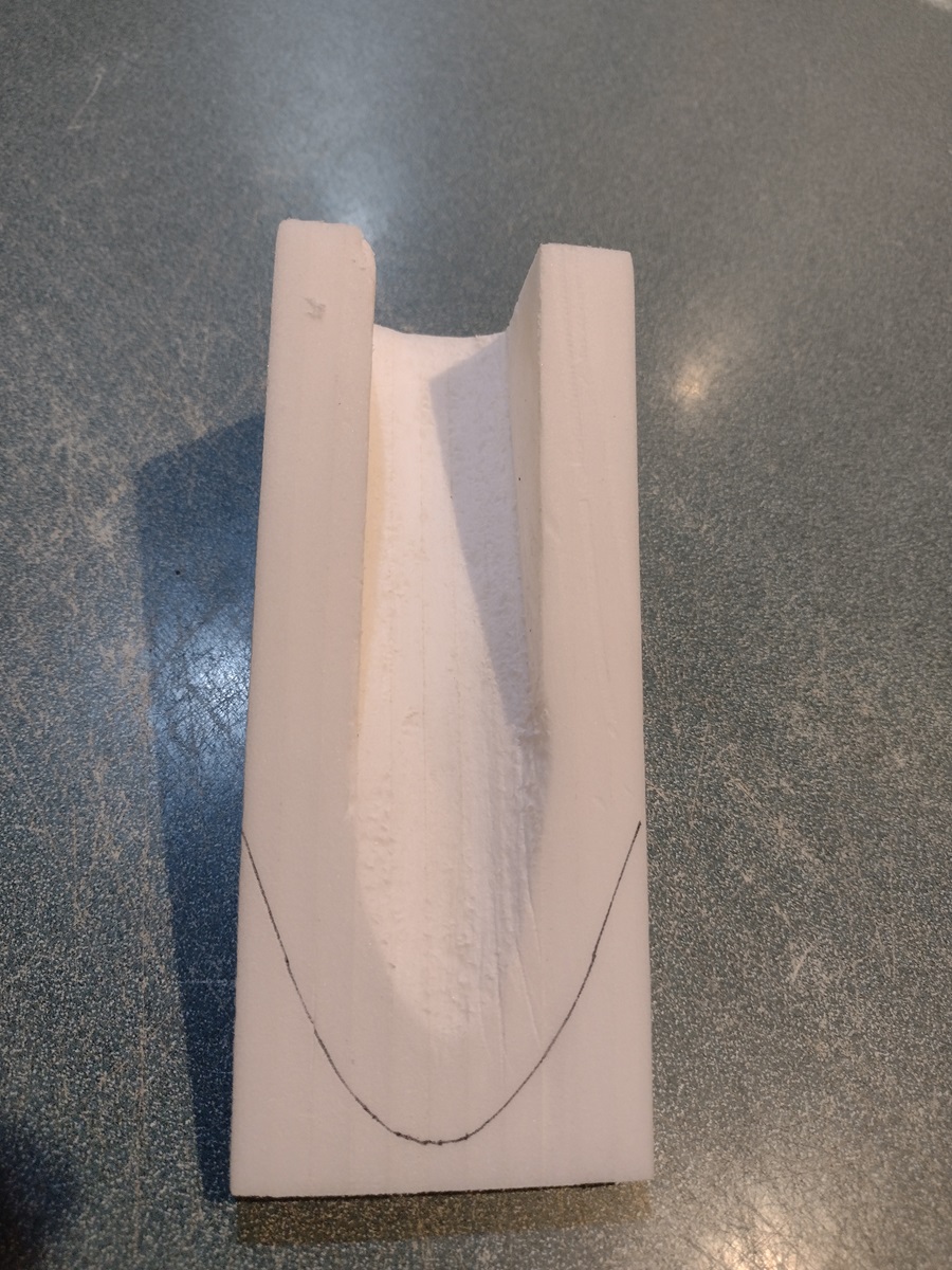
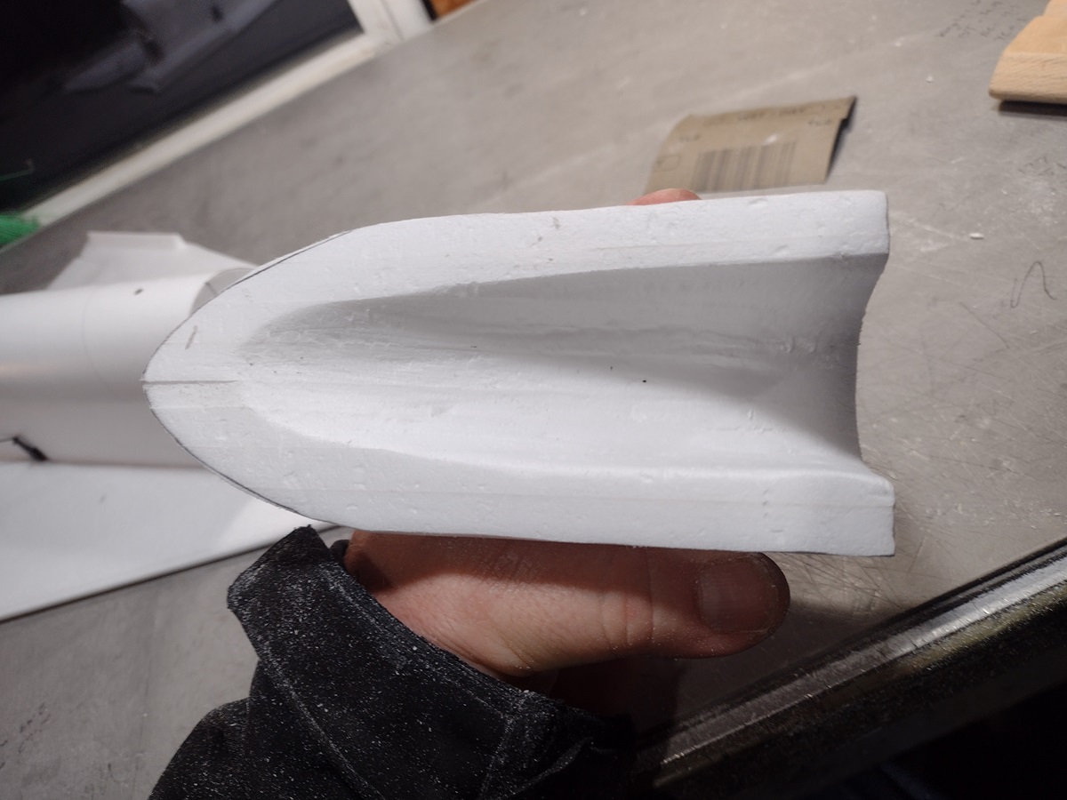
- Use a rasp or hot soldering iron to hollow out under the cone to fit the nose weight and battery, don’t go too deep as you have to round the nose and don’t want to go all the way through. You want the hollow area to be about 4″ long at least and about 1/2″ deep at the front and 1.25″ or more at the rear. You want the hollow to be a bit wider than the hatch opening to prevent you from gluing it to the hatch door.
- Test fit then glue the rough shaped nose to the wing and front former.
- If for some reason you glue to the hatch or glue gets in the hatch and you can’t cut it to free it or destroy it trying to get it loose, just use the spare depron to cut a new hatch and tape it into the wing as before.
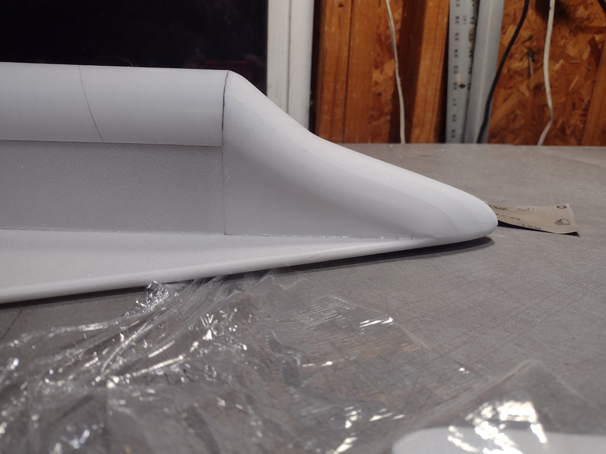
- Finish shaping/sanding the nose to fit the wing and body joints. I switched to 400 grit for final sanding. Make sure you don’t glue the nose to the hatch!!!
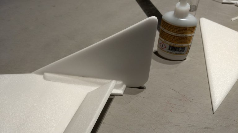
- Glue the two gussets on each wing tip that will support the stabilizers, make sure each wingtip is sanded at 90 degrees to the wing.
- Glue each stabilizer to the wing tip. Use plastic wrap under the wingtip to prevent you from gluing to the work bench. The rear of the stab will stick back beyond the end of the wingtip about an inch and the front will extend forward to allow you to sand it to shape to match the wing. Trim and sand the wingtip/wing joint to a nice rounded shape.
- Attach the servos to the receiver.
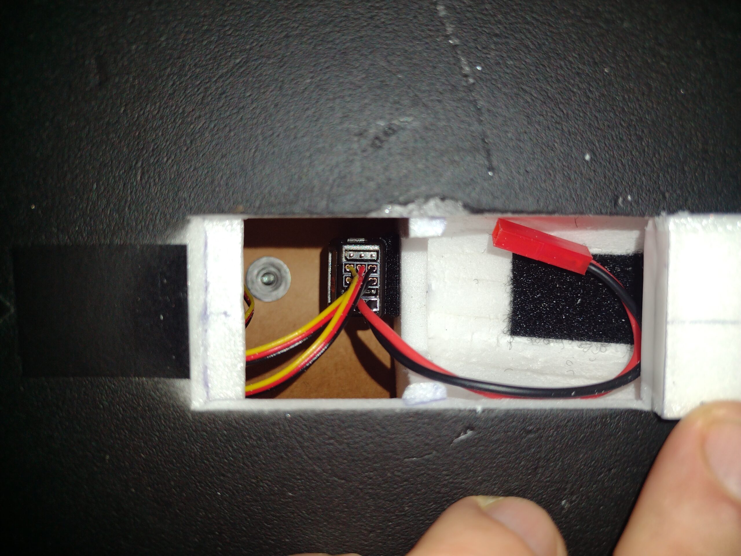
- Use velcro to attach the receiver inside the hatch against the backside of the front former and the battery to the inside of the nose.
- Install your loaded motor and battery, check control throws and directions. Zero out the control surfaces using the radio trim settings.
- For boost I found I needed a small bit of up elevator, maybe 1/8″ or so. The roll is very sensitive in this model. I used flap elevator trim and flight modes to set in boost and glide trim on the same D switch.
- I used about “12%” up in my flap/elevator setting for elevator for launch and about 35-40 up elevon for glide in my spektrum DX-8. I use the flap switch for boost/glide trim and have it tied to two flight modes, each has independent trim for elevator/aileron for each flight mode so you can fine tune separately. I used dual rate of 100% for elevator for both flight modes, and 30% aileron for boost and 75% for glide position. If this is confusing see the general instruction tab on the site and there is a video about setting up launch/glide trim and flight modes. This corresponds to around 1/2″ of throw at 100% for elevator and about 1/4″ or a bit less of aileron throw at 30% dual rate setting.
- Balance the model upside down on the mark indicated at the top of the page in red for boost CG, you will need to add nose weight of around 2 oz typically. I put some shot in a baggie taped to the outside of the model and added a little at a time till I got close, then glued in the shot through the hatch into the nose using foam safe CA+ dribbled on top of it to secure it, I then added a little more at a a time to achieve slight nose down balance. Do not use all the lead, just the amount required.
- Tape off the rail buttons and paint the model flat black. Testors or Krylon short cuts does not melt the white vinyl, it took about one can.
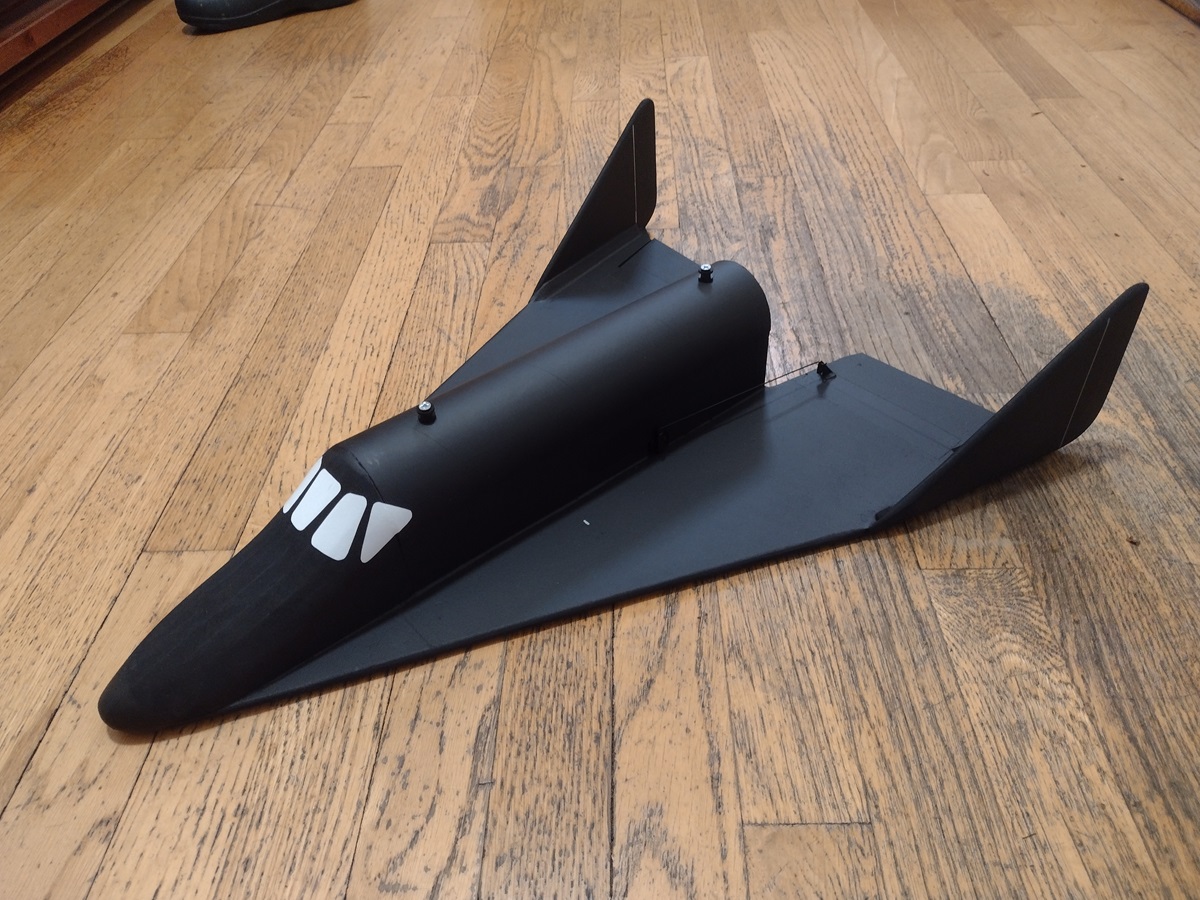
- Cut out the window templates and use the white orcal 651 vinyl to make the windows for the cockpit. There is a center semi rectangular piece, two polygon side pieces and two triangular rear windows. After attaching the decals, use a hot hair dryer to soften them and rub them into the model.
- Double check the balance to make sure the paint did not change the CG, on mine it did not.
- The model boosts fast and is very roll sensitive on boost. Keep the model vertical and then push over at burnout and flip in the glide trim, adjust as needed. My rtf weight was 8.4 oz.
- Kit parts, top row left to right, Nose sections, front and middle formers, rear former, side plates, wing tips, body tube, Bottom row, Wingtip gussets, hatch lip, spare depron, wing
- Bagged Parts, left to right, Cockpit templates, vinyl, pushrods, rail buttons, spar, battery wire, motor mount, lead weight, blenderm, velcro
- Glue taped wing joint.
- Cross spar installed, glued and taped over. Hatch cut out and tape hinge and handle installed.
- Hatch lip glued in place.
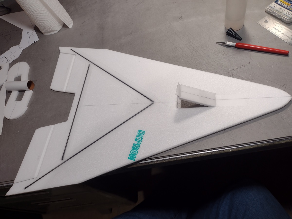
- Formers glued in place.
- Motor mount glued in place.
- Pushrods/horns installed.
- Servos hooked up and glued in place and servo wires routed forward.
- Test fitting side plate.
- Side plate installed with cutout for servo arm.
- Other side plate glued in place.
- Top Fuse body tube cover installed, don’t forget to put in the rail buttons like I did:)
- Cockpit pieces laminated with 3m-77 spray adhesive
- Rear marked for fuselage shape
- Nose marked on bottom and hollowed out
- Nose sections glued together and rough shaped/rounded.
- Bottom hollowed out, don’t go too deep!
- Nose glued to front wing/fuse.
- Nose final shaped.
- Wingtip gussets rounded at ends
- Gussets glued to wing tip
- Stabilizer glued to wing tip, note stabilizer extends to the rear of the tip about 1″ and front will overhang to allow shaping to the wing.
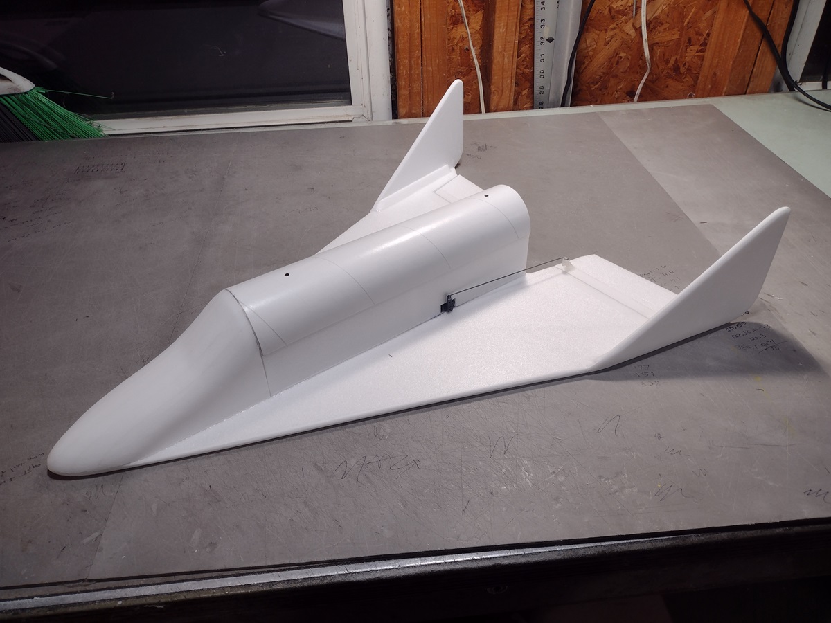
- Wing tips installed and sanded to blend at the front of the wing and the bottom corner rounded
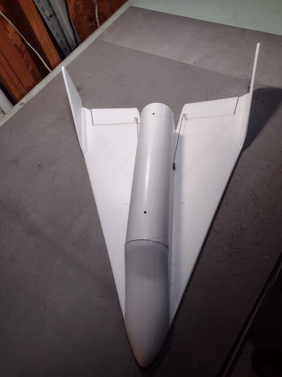
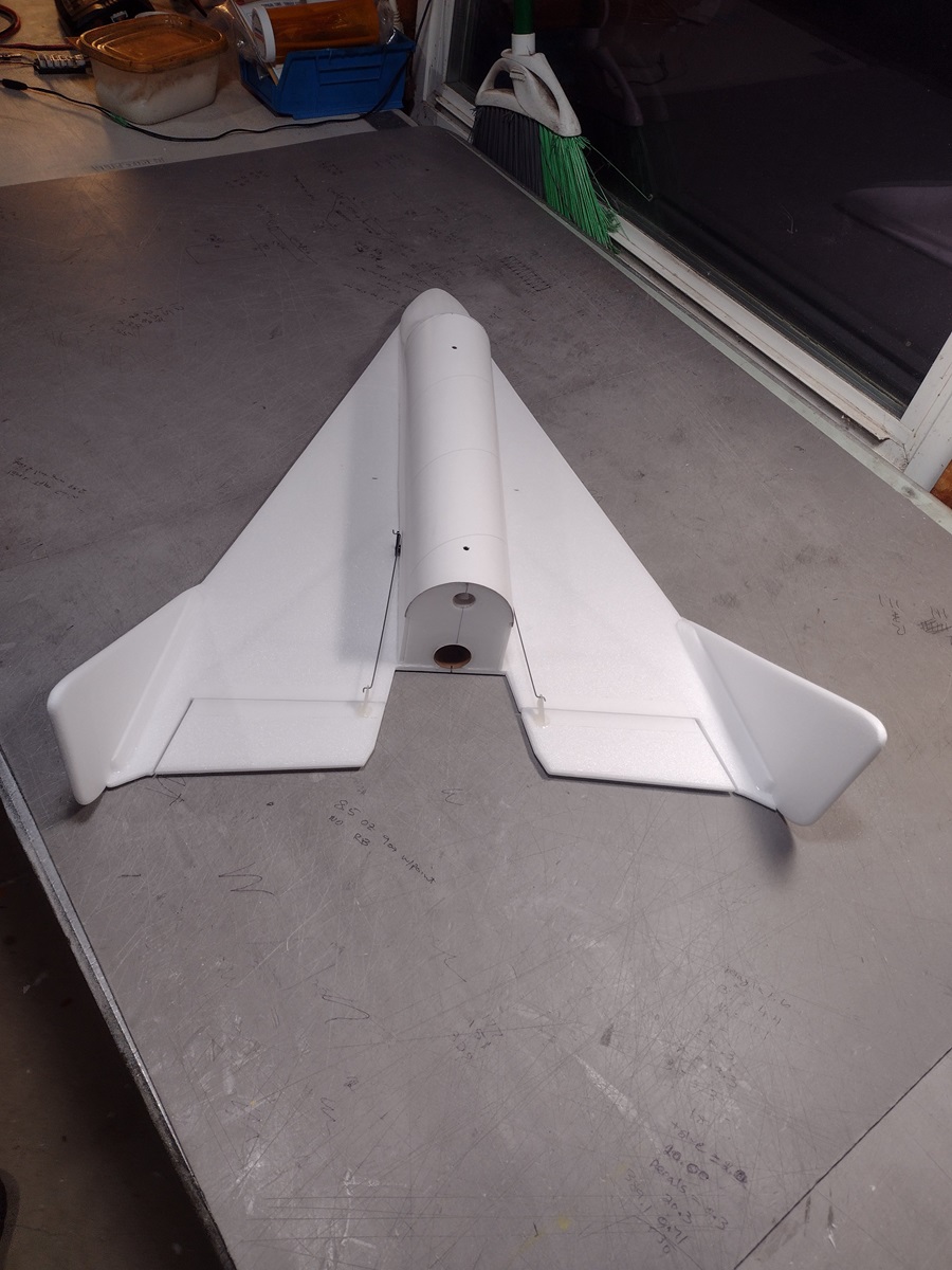
- Top view of completed airframe.
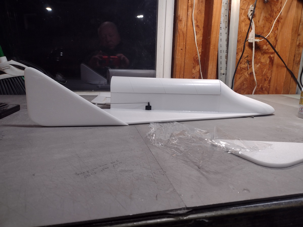
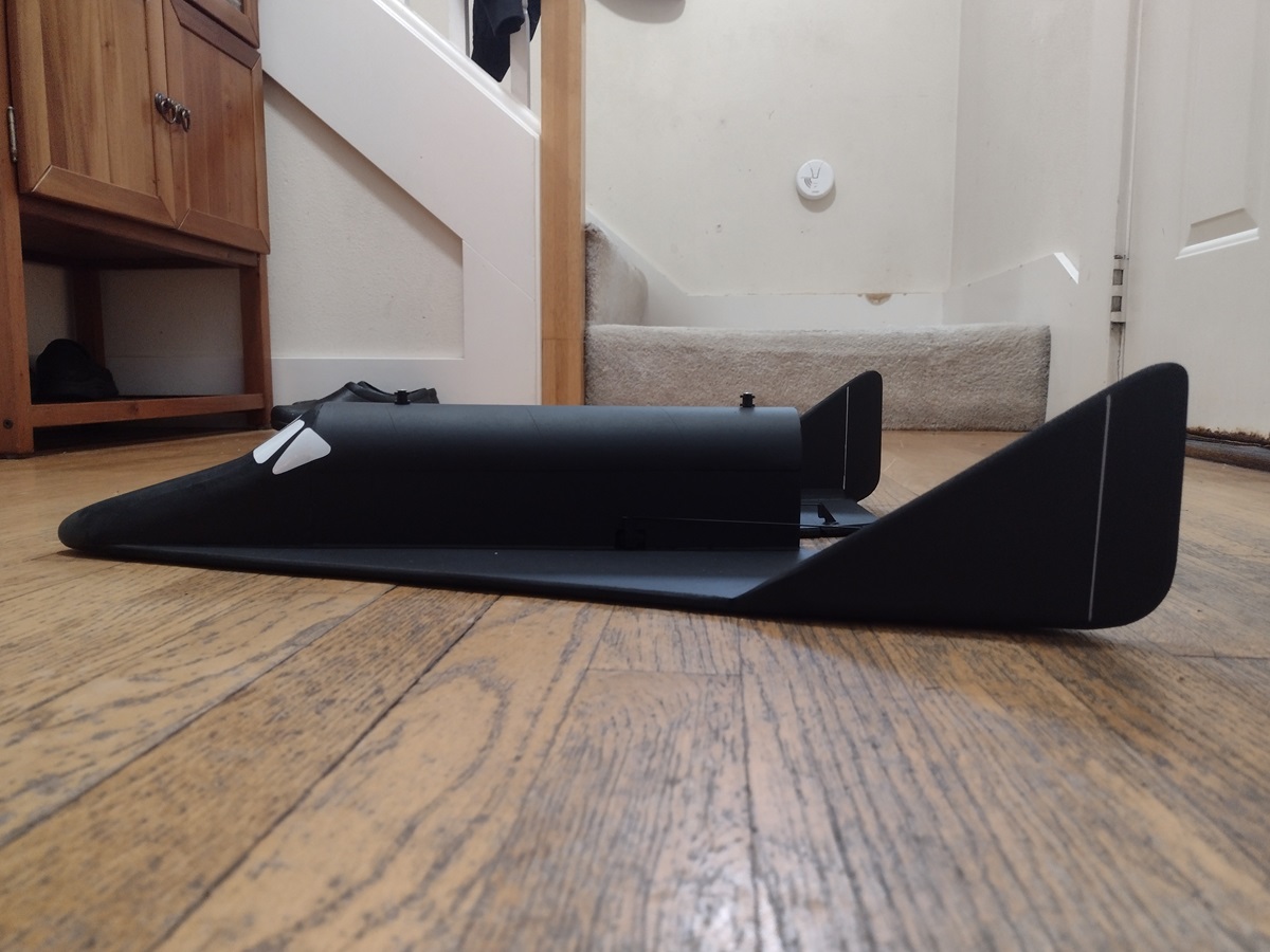
- Side view of completed airframe.
- Rear view.
- Receiver attached to rear of front former and battery velcro under nose section.
- completed model with cockpit decals.
