The Shuttle RC Rocket glider kit is a simplified shuttle design that is lightweight and very easy to assemble. It comes with 2.6″ white tubing for the body and 6mm depron wing and tail surfaces. The body tube is pre-slotted for the tail and rail button holes are pre-punched. Elevons are pre-hinged and spar is pre-installed. Construction and radio install is very simple. Length 23″ long, 18.5″ wingspan, 2.6″ diameter, 8 oz ready to fly for reloadable 24mm Aerotech composite E-6RC motors only. Please refer to the General information for all kits tab above, then read these instructions completely before starting assembly. Excellent high quality cut vinyl decals in US/Buran style or Moonraker style are available separately from stickershock.com HERE:
CG location for rocket flight: 8″ forward of the rear end of the body tube with loaded motor and battery ready for flight.
Boyce Aerospace is offering a 3-d printed nose cone that fits the Shuttle that will fit this model HERE You will simply trim the front of the wing off ahead of the body tube, use the Boyce cone and then sand/blend the wing/side plates to match if needed. You will not need the OMS pods as they will be in the way of the rail buttons. The display nozzles can be used as that fits into the motor tube.
**Note, The decals that stickershock provides simulate the OMS pods and look just fine in flight. However, if you want to add the OMS Pods, contact me before you order and I can cut the rail button holes on the bottom of the body tube and include some styrene disks and longer screws to go through the wing, but there is higher risk of rail button damage on landing so I don’t recommend it. Additional instructions are HERE:
Welcome to the world of rocketplanes. This is not a model for a novice RC pilot, but anyone who is comfortable with RC flying of a medium speed aileron controlled model should be fine. Read through the instructions, look at the photos and be sure you understand the step before commiting to cutting or glue.
Identify all pieces, the kit should contain:
1 wing taped together 6mm depron
2 pushrods 2/horns
2 3mm depron side plates
Foam Nose profiles 6mm depron
1 vertical stabilizer 6mm depron
1 Body Tube
1 coupler, may be placed inside the body tube for shipping
24mm Motor mount
3 13/16″ x 2.75″ strips to center the motor tube.
Velcro(for battery and rx/bec attachment)
2 Rail buttons with t nuts/screws
Lead weight
Spare foam (for testing paint, glue, and sanding the edges to see how it behaves)
Notes before starting:
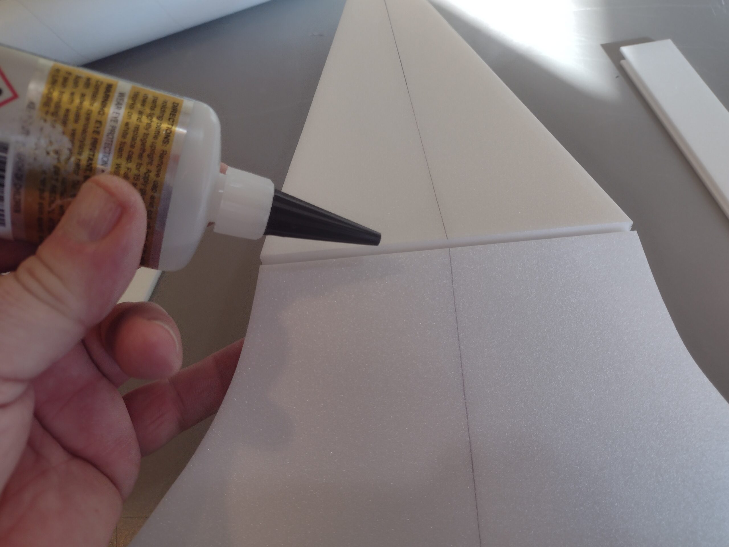
Foam safe CA+(Bob smith super gold + is good) is the only glue recommended for primary construction. You will also need foam safe accellerator to set the glue. 3m-77 is recommended for laminating the nose pieces, spray each side of each piece lightly, allow to dry for a few minutes and then press together. If you get any overspray you can use the CA accellorator to safely remove the glue by spraying and wiping.
I use a straight edge and exacto knife to put a light 1/16″ to 1/8″ bevel on the leading and trailing edges of the wing and stabilizers before assembly. You can also use a very light touch and 400 grit sandpaper and a block to do the same thing. Do this before you assemble the model.
Assembly:
- Glue the taped wing joint and lay flat to set.
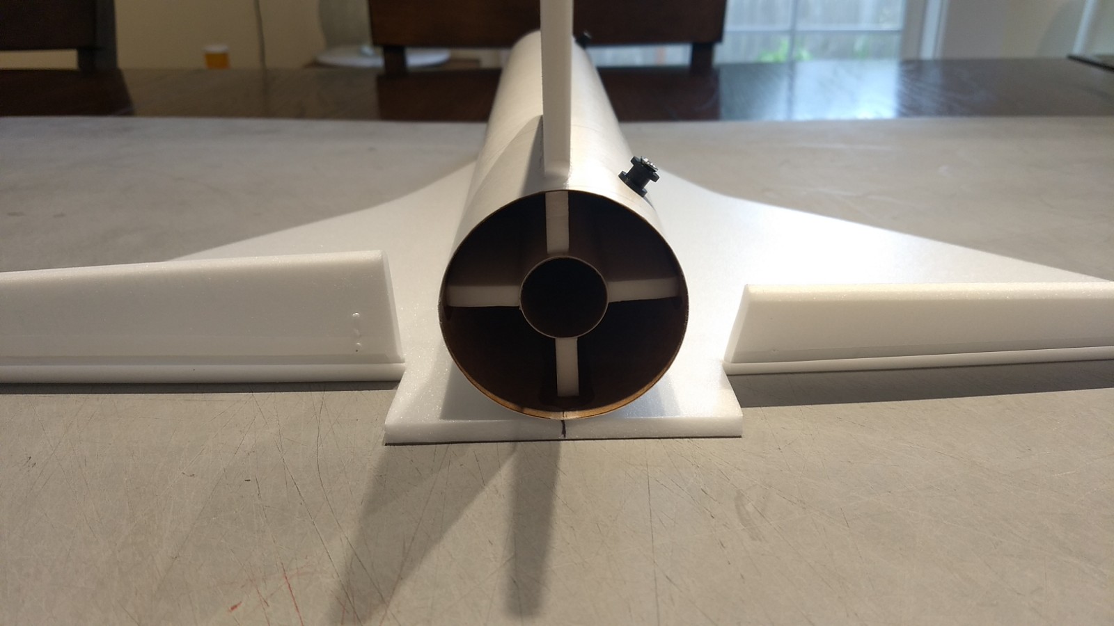
- Apply glue to the wing line on the bottom of the body tube, lay the body tube on the top of the wing and make sure the front and rear alignment lines are lined up with the center line on the wing at the front and back. **Note the rear of the wing will be even with the rear of the body tube.
- Install the front and rear rail buttons at this time.
- Test fit the vertical stab into the slot in the body tube carefully. Glue the vertical fin into place. Apply a light filet to both sides of the vertical stab on the inside and outside of the body tube.
- Glue the 2.75″ long foam strips on three of the motor tube lines
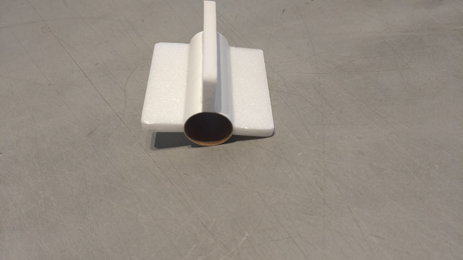
- Test fit the motor mount into the body tube. Make sure it fits, or sand the foam tabs lightly till it will insert without deforming the body tube and makes contact with the tube and fin tab. Glue the motor tube in place flush with the vertical stab tab at the rear, it will be inset into the body tube about half an inch, make sure the vertical stab stays vertical.
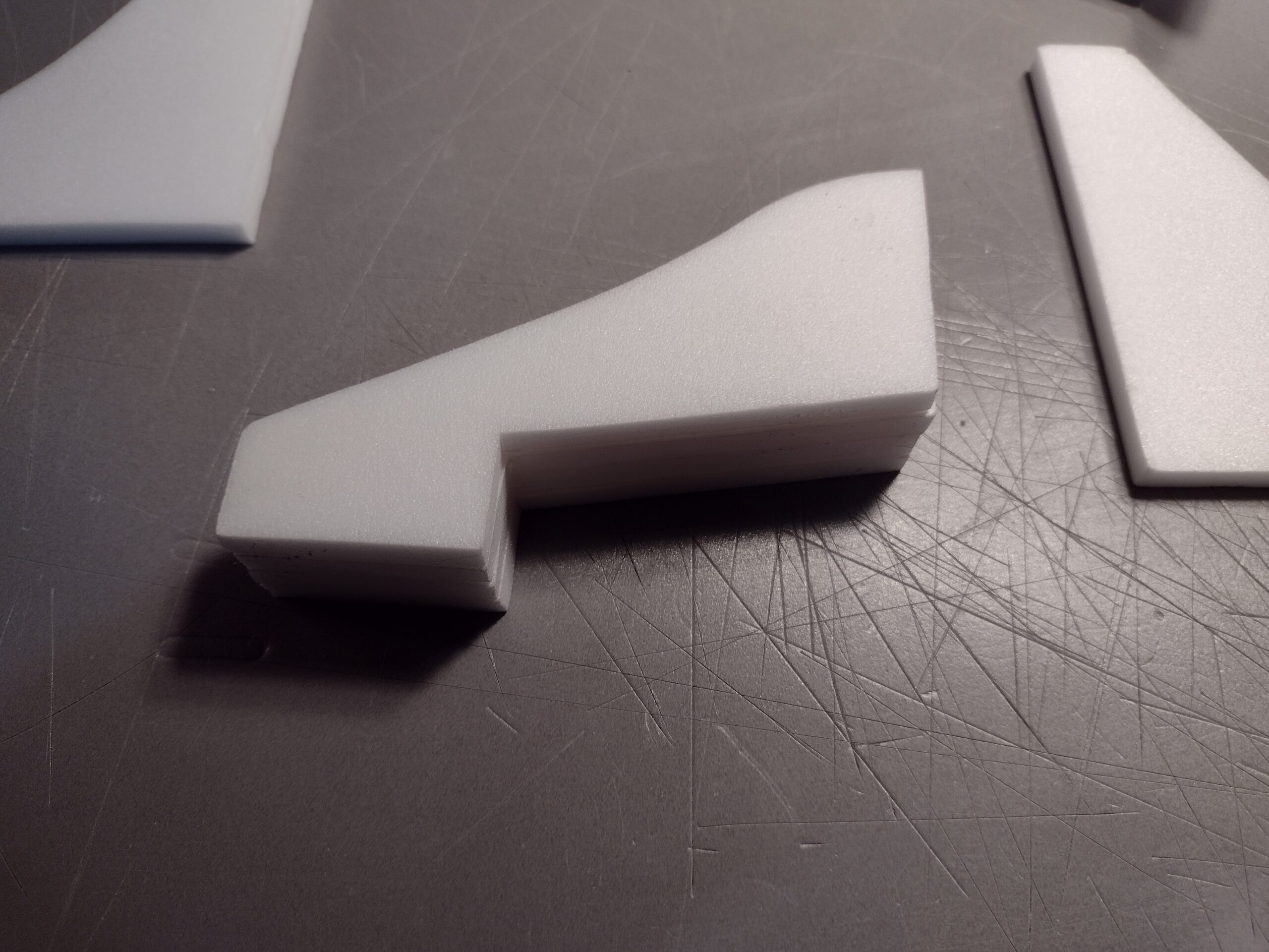
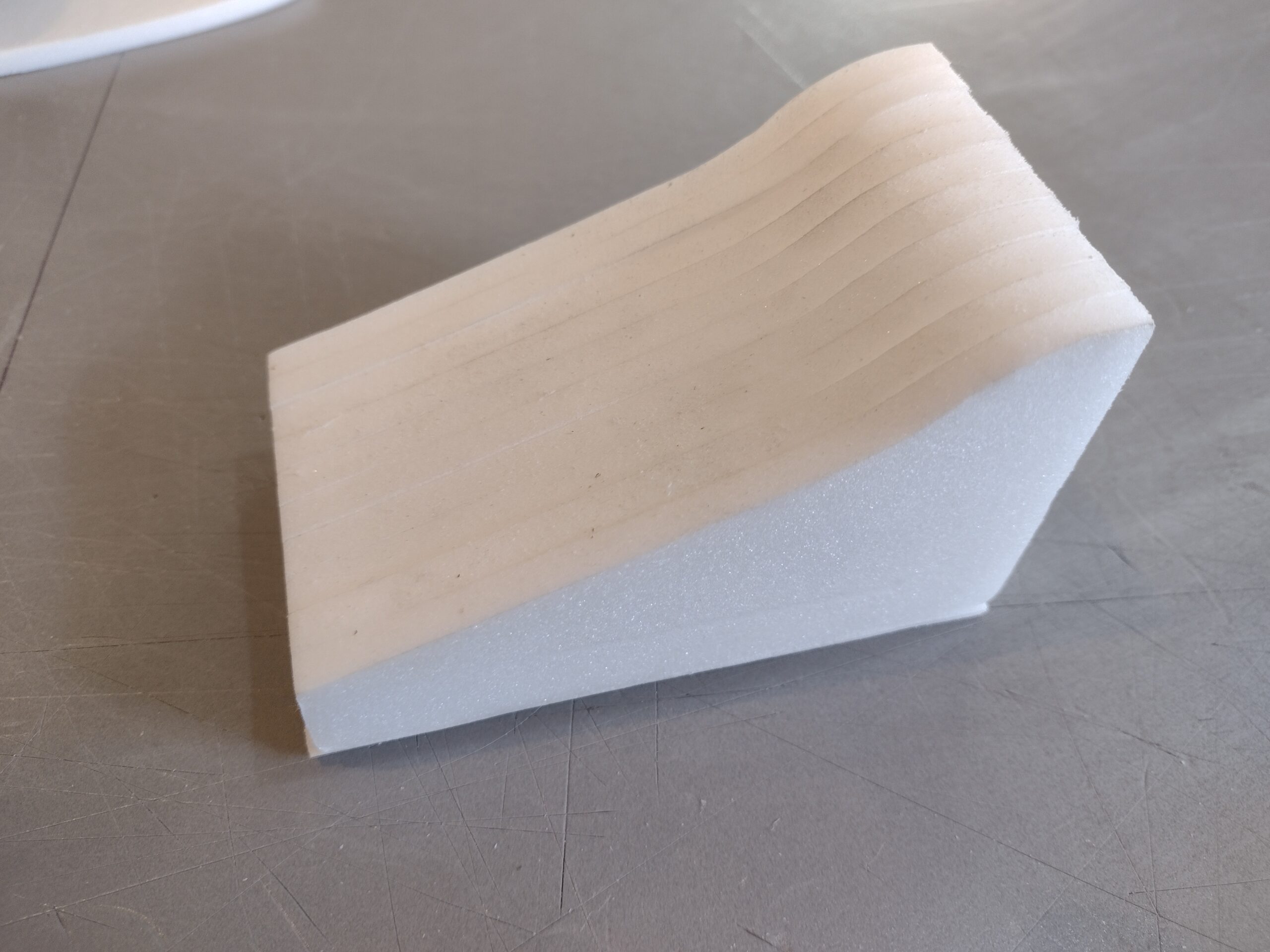
- Cut a pocket into four of the nose sections approximately 1.5″ long by 3/4″ tall. See photo, don’t cut out too much as you can sand through when shaping the cone. This step is optional if you do not do it you will just mount the battery into the body tube and nose weight into the coupler, it will just make the model heavier.
- Laminate these sections together using 3m-77 spray adhesive. Spray both sides and let dry for about a minute then press together. You can use the foam safe CA but it will leave a hard ridge inbetween the plates and make it harder to shape the cone.
- Laminate the rest of the nose sections on each side of the section with the pocket so you have a pocket in the middle of the cone assembly. Only spray one side of the outer two nose plates, if you forget you can use spray accellerator to remove excess spray adhesive. This will allow you to mount the nose weight and battery further forward and avoid excessive nose weight.
- Sand the rear and bottom surfaces of the cone assembly lightly to make sure they are flat.
- Test fit the nose section against the body tube, it will be slightly wider than the body tube to account for the side plate thickness. If it is not glue some of the spare included depron on one or both sides, most will be sanded off so you don’t need a lot, just at the rear where the side plates touch.
- Glue the bottom of the nose section to the front of the wing and against the body tube centered on the body tube but DO NOT Glue it to the body tube!
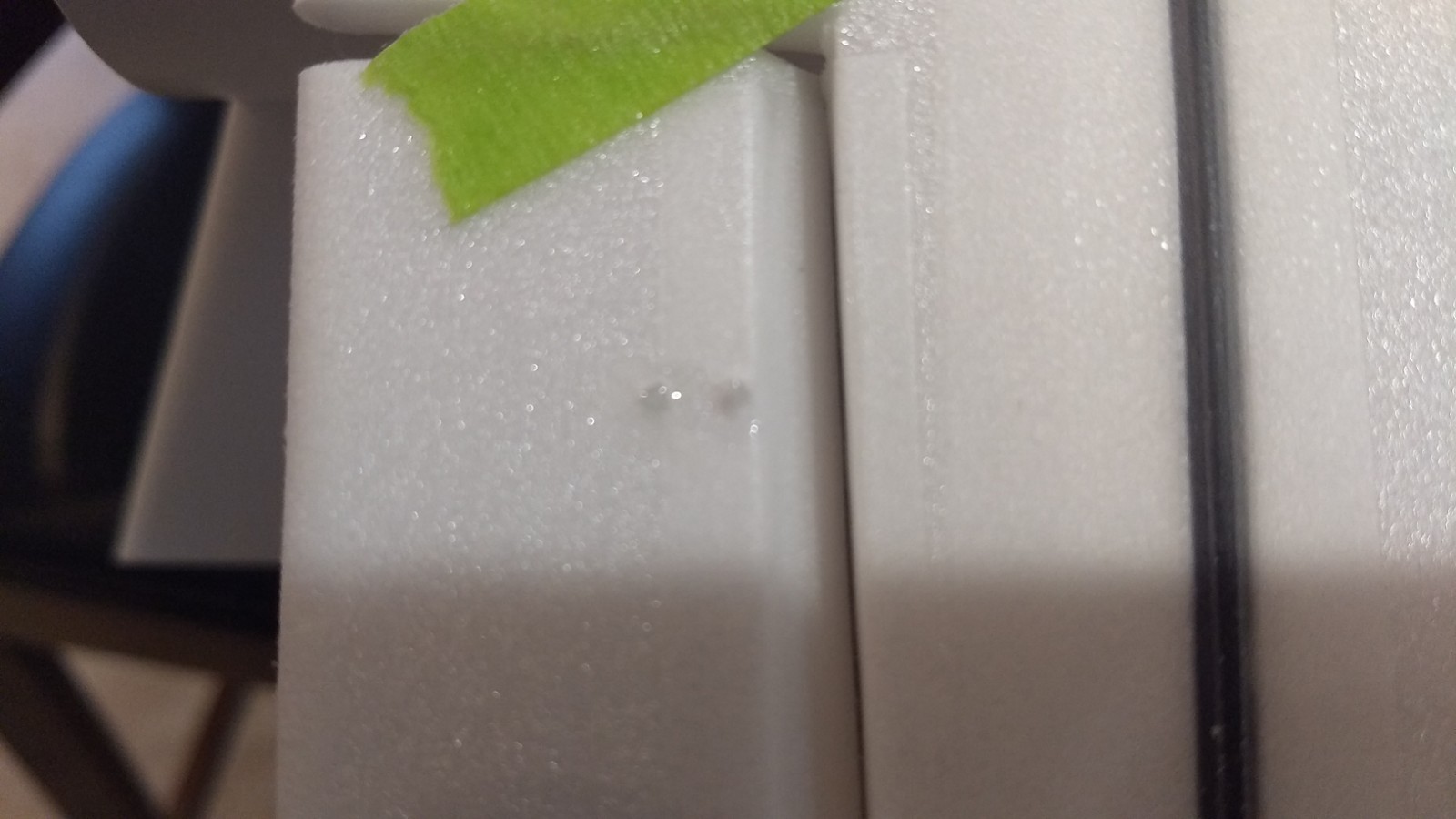
- Sand the top edges of each 3mm foam side plate to a nice tapered/rounded shape using 400 grit paper and a sanding block. Use a light touch. See photo.
- Glue each side plate to the wing and the fuselage and make sure they are well set before continuing. The front of the plate will be butted up against the nose assembly and the rear is even with the rear of the body tube. DO NOT glue the side plate to the nose assembly.
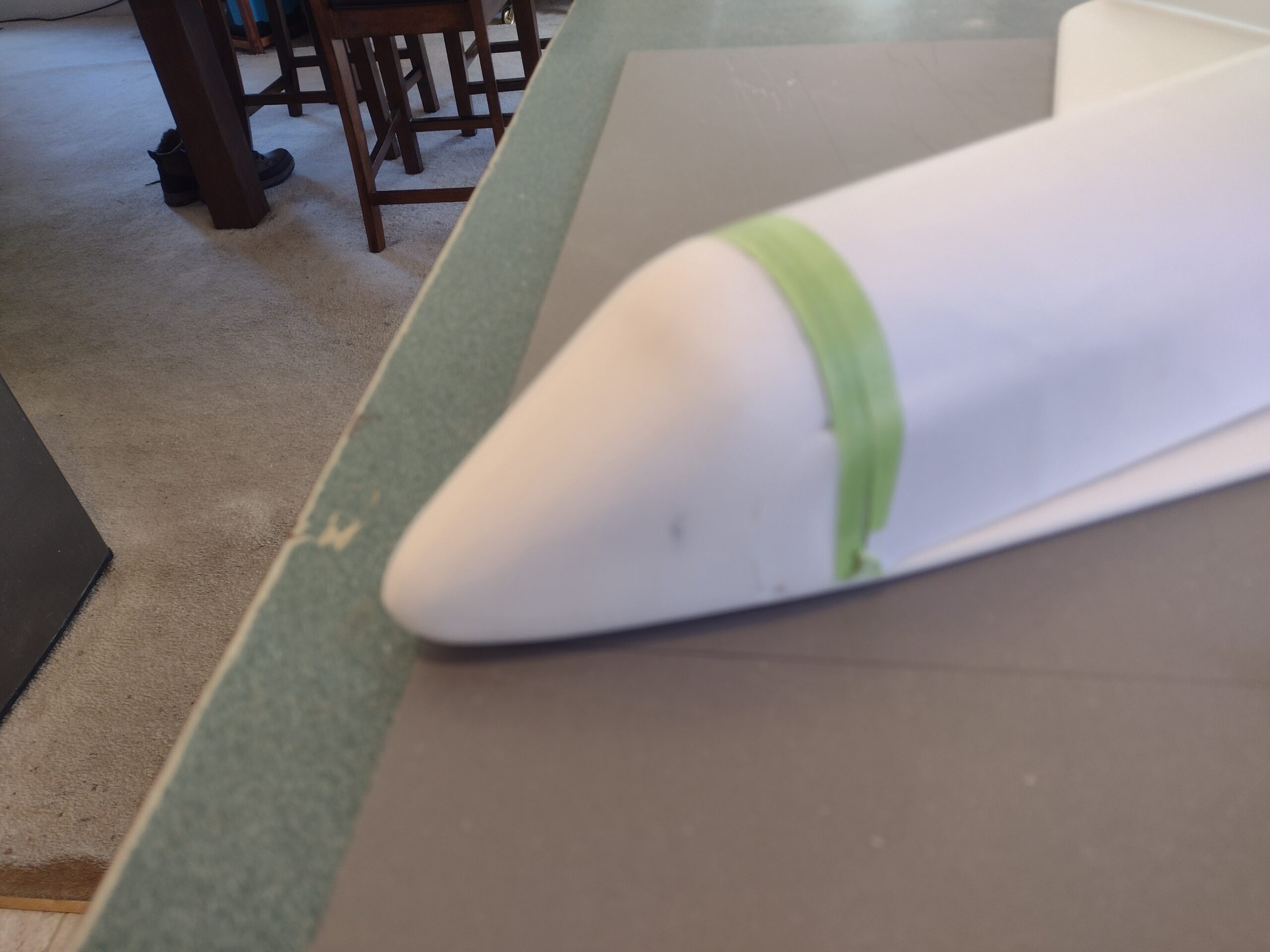
- Tape over the front of the body tube with masking tape and paper. This allows you to shape and sand the cone to the body tube profile without risk of scuffing the tube. You may wish to remove the front rail button temporarily to make this step easier.
- Cut, saw and sand the nose cone to a nice rounded shape. The foam is oversized to allow you to shape it to your liking. I used a serrated bread knife to make the primary top view cuts since it is long and thin and makes quick work. Use an exacto and 220 grit paper for rough shaping, then go to 320 and 400 to smooth things. I first shape the top view and curve to the nose, then shape the top and bottom as viewed from the side, then slice the corners and round the top and bottom edges to shape. Once happy I removed the paper/tape and did a final blending by hand.
- Cut the nose cone free by cutting through the bottom of the wing where the front of the body tube stops.
- Slide the coupler into the body tube part way, then set the model on a table top and tack glue the coupler to the nose cone in a couple of places making sure it will line up centered with the body tube. DO not glue the coupler to the body tube.
- Check to make sure the nose cone lines up once the glue sets, buy pushing the cone in all the way. If it is not quite right, not pop it loose and re-do it till it lines up nicely.
- Remove the cone and put a nice fillet of glue inside the coupler only to lock it in place against the foam.
- If you want to toughen the cone up a bit, you can coat the tip with the foam safe CA and a gloved finger, use a light application and smear thin, let it try naturally and don’t use spray setting solution directly as it can make the surface bubble. I prefer to spray the gloved finger with setting solution and then rub that quickly all over the cone. I usually do one or two light coats and lightly sand with 400 afterward.
- Apply CA+ to each of the control horns and press them in place in the top of each control surface into the pre-made holes. Note the pushrods will angle inward toward the body tube, there is a left and right.
- Apply glue to the prongs on the bottom of the wing to lock the horns in place.
The basic construction is now complete.
Radio Installation
Note: Your radio needs to be configured for Delta or elevon mixing, this means that the servo arms will move the same direction during elevator stick movement and opposite for aileron stick movement. Connect your servos to the receiver one in the aileron connection and one on the elevator connection and apply power. Use a servo arm at least 9/16” long and with holes small enough that there won’t be slop with the pushrod wire when installed. I use the hole furthest out on the servo arm, to maximize movement. On some servos there are a long two-ended servo arm, you can trim off one end if needed to get sufficient length. Zero out any trim settings on the transmitter.
- Connect a servo to each pushrod. If the pushrod is too tight, you can use twist an X-Acto knife in the servo arm hole to make it larger, but be careful and do not make it too large. Once connected, tape each servo in place so that the control surfaces are centered. Look at the model from the rear. Moving the transmitter stick back(up elevator) should move both elevons up. Moving the transmitter stick to the right should move the right elevon up and the left elevon down. If you can’t get the servo reversing to give you the right polarity try swapping aileron/elevator inputs to the receiver or turning the servos over and swapping the servo arms to the other side of the output shaft. If that is correct, continue.
- Mark where the servo will be when the control surface is neutral and cut a pocket into the side plate and through body tube so that the servo is inset nicely. I clipped off the tabs on the servo with the mounting holes so it insets a bit further and looks nicer. Repeat on the other side. Route the servo wire into the pockets on each side and out the the rear of the model going through the same quadrant of the motor mount and re-connect the servos to the receiver. Once done you will push the receiver back through and forward to the front of the model. If your servo wires are too short you may need to use some short 6-8″ long lightweight extensions.
- With the radio still on, put a moderate amount of glue on the servo, being careful not to get any near the output shaft, and set it in place on the wing in the pocket you just cut, keeping the control surface centered. Do the same to the other side. Make sure the glue is set before continuing.
- Make sure the control surfaces are centered, use trims if needed. Now measure the control surface movement. Full elevator movement should be 1/2” in each direction, aileron movement should be 3/16″-1/4″ in each direction. (My model was extremely roll sensitive, you may want to use exponential to reduce throw around center to avoid overcontrolling or reducing throw after the first trim flights if needed)
- If you have a flap/elevator mix you can program elevator trim to a switch setting. I use the long D switch on my dx-8, up is launch and down all the way is glide. The model needs approximately 3/16″ to 1/4″ of up trim for glide. You can also use flight modes to set different launch and glide elevator trim settings and control those via the D switch and using trim settings set to fmode and not common. I also use the fmode audible naming up is “launch mode” and down is “landing mode” so I can hear the switch position and make sure I don’t launch in landing mode with up trim.
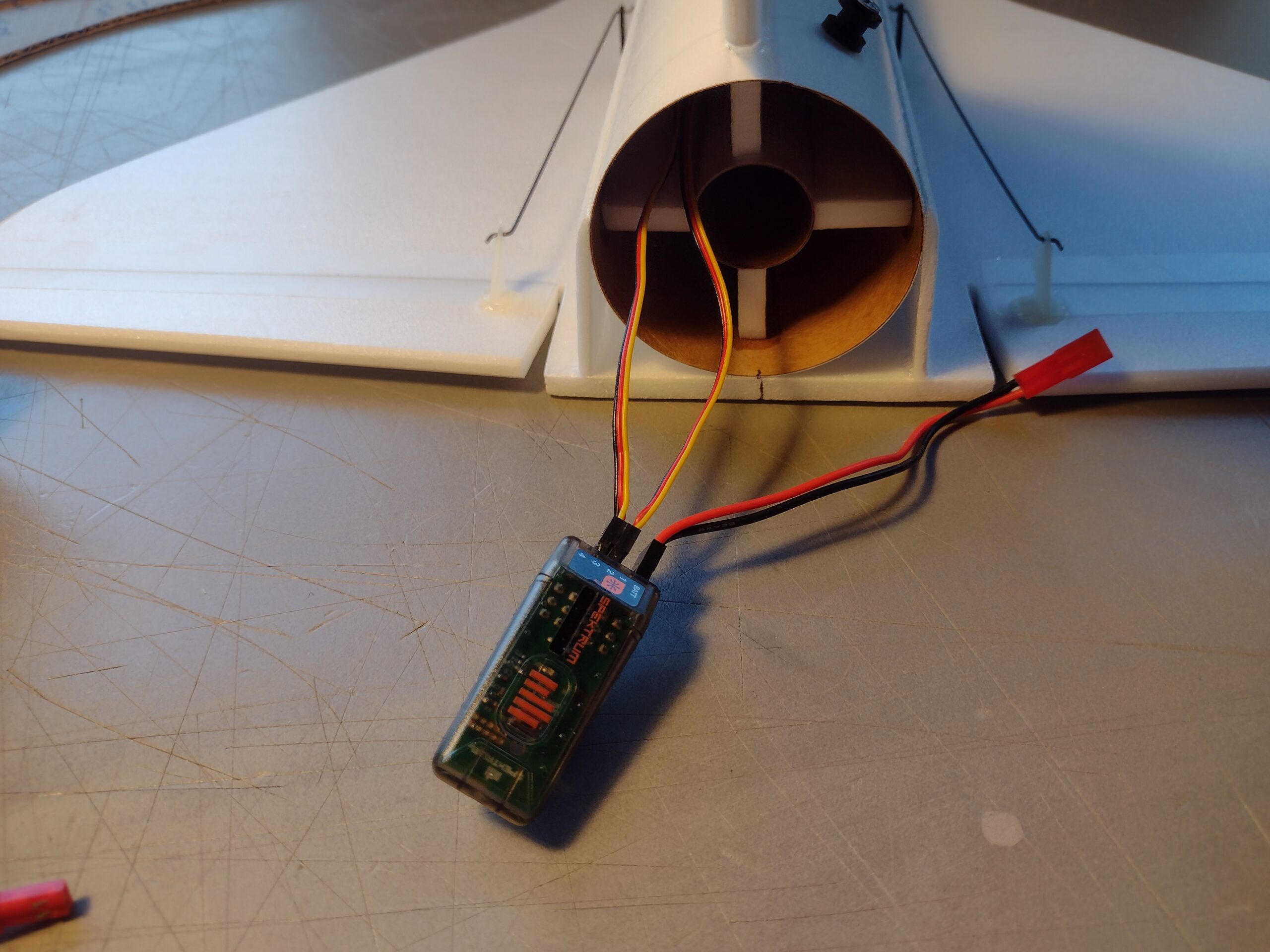
- Route the receiver all the way forward to the front of the model, on mine it would go just to the end of the body tube without having to use servo extensions.
- Use a small piece of the included Velcro to attach the receiver inside the body tube inset about 1″ so that the nose cone shoulder won’t hit it.
- I used the remaining velcro to mount the battery inside the nose cone recess you melted into the cone.
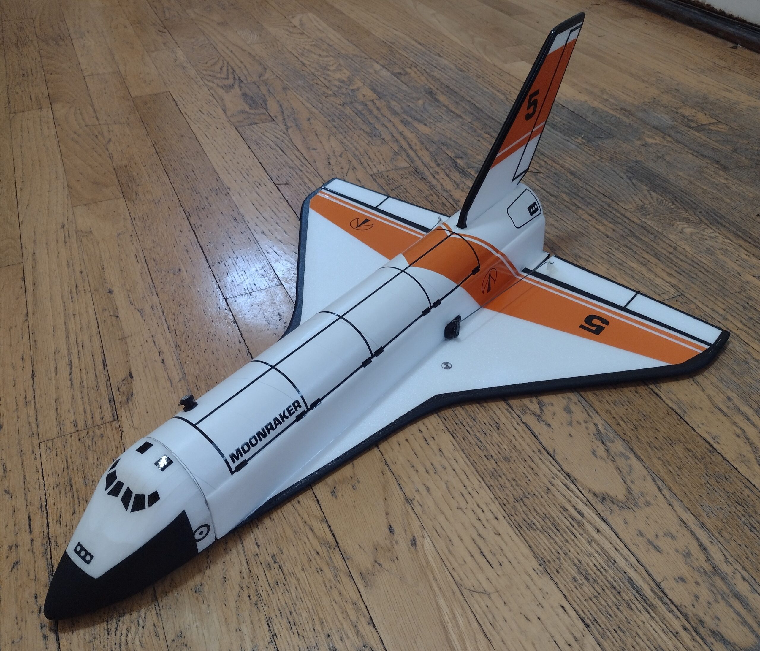
- If you use the stickershock markings apply them after painting, you will need to trim the wing, body and tail orange stripes to fit exactly before applying them, they are slightly oversized to allow for your sanding/painting variations. Once you apply the markings, use a hair dryer on hot to warm the markings and them push them down into the foam surface with your finger. The will really conform and stick down well. I cut the cockpit decals into a right and left half and then applied them to the right angle so they wrap around correctly. If you choose the moonraker set the wing, body and tail decals are slightly oversized and will need trimming to fit, it is too hard to predict the masking of the edges and alignment to get everything perfect for all kits exactly. Just take your time and it will be fine.
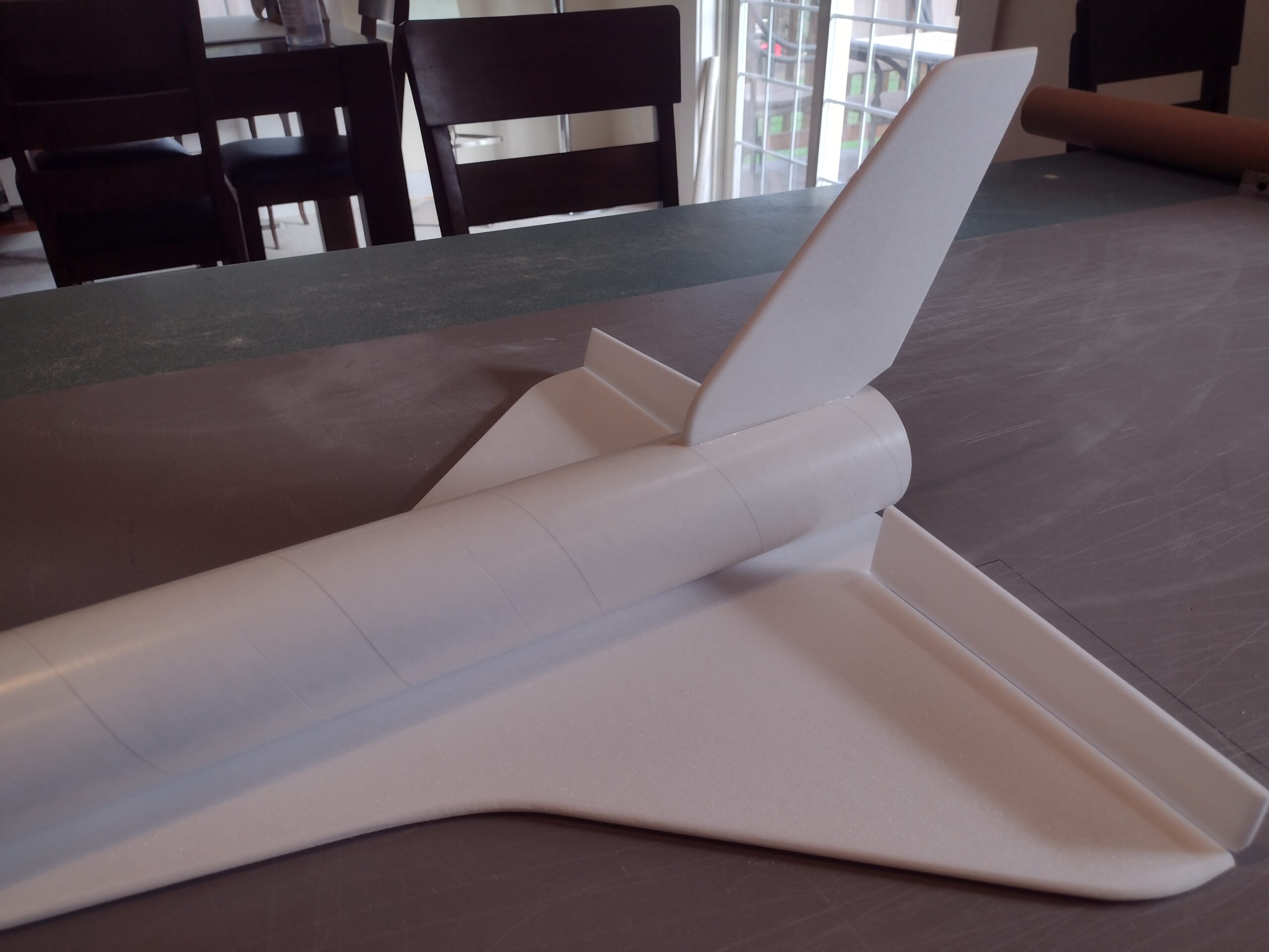
- For painting the bottom of the model I can only recommend testors/model master or krylon short cuts enamel flat black spray at this time, others have used liquitex spray which is a latex which should work but I have not personally tried it. I left the body tube and top of the wing bare(no paint to save weight) and just masked off and painted the bottom and edges of the wing and tail and the nose cone flat black. Use the pictures as a rough guide for painting.
- You can use a fine line black sharpie or auto trim tape to add extra details like the door panels or split elevons if desired.
- Insert your heaviest loaded rocket motor into the motor mount
- Support the model at the balance point indicated for boost. I use two chopsticks pointed up and held in place with a small hand vice. Place the model upside down on the balance point indicated at the top of this page in red. Use pieces of the included lead weight as far forward into the tip of the nose to balance it, or in the tail as needed. Glue the lead weight in place so it does not shift during flight. Do not try to fly the model too nose or tail heavy. Remember, a nose heavy model flies poorly, a tail heavy model flies once. You should not need all the nose weight, I provide extra, use just enough for correct balance.
- Re-install the receiver and battery
Flying: See the General Instruction link at the top for flying instructions. Be ready on the first few flights to keep the model straight till you have the trims set perfectly for boost and glide.
-
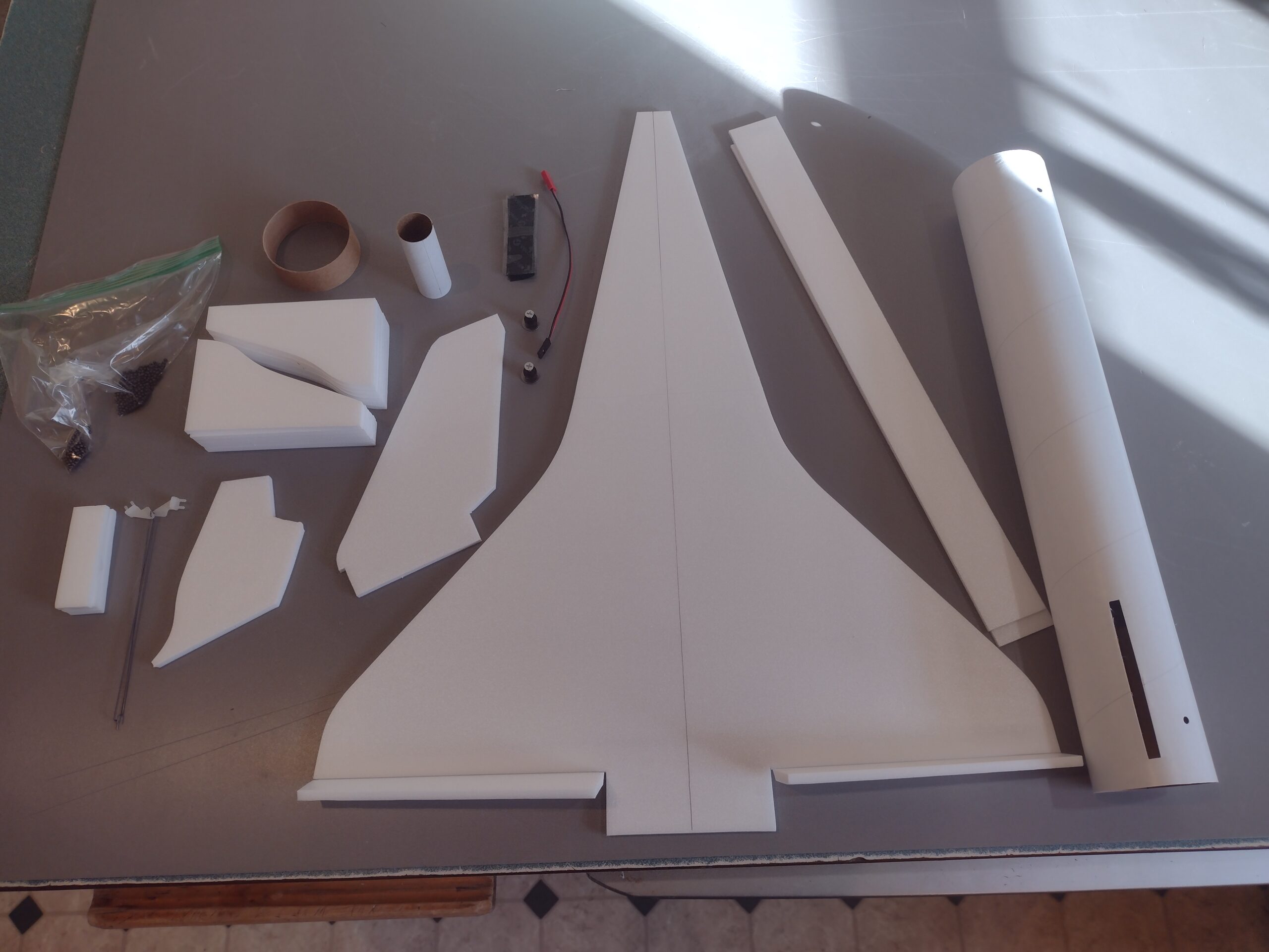
- Kit parts
-
- glue taped wing joint and lay flat to cure
-
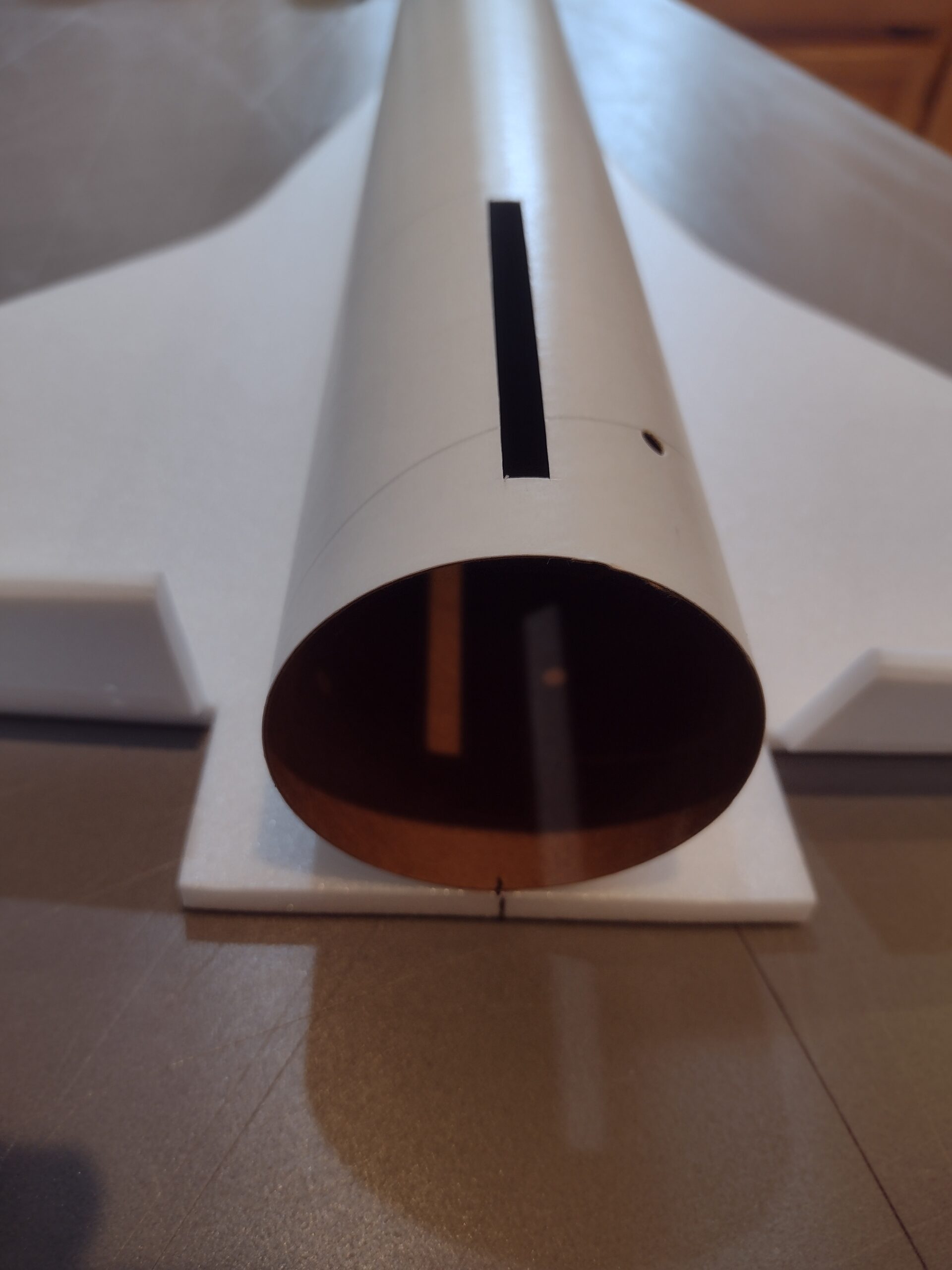
- Glue body tube to the wing with the rear of the tube flush with the rear of the wing, and aligned on the centerline.
-
- Test fit then install Vertical stab.
-
- Glue three foam strips to the mmt on the lines marked.
-
- Install the rail buttons then test fit then install the motor mount recessed even with the vertical stab tab, about 1/2″
-
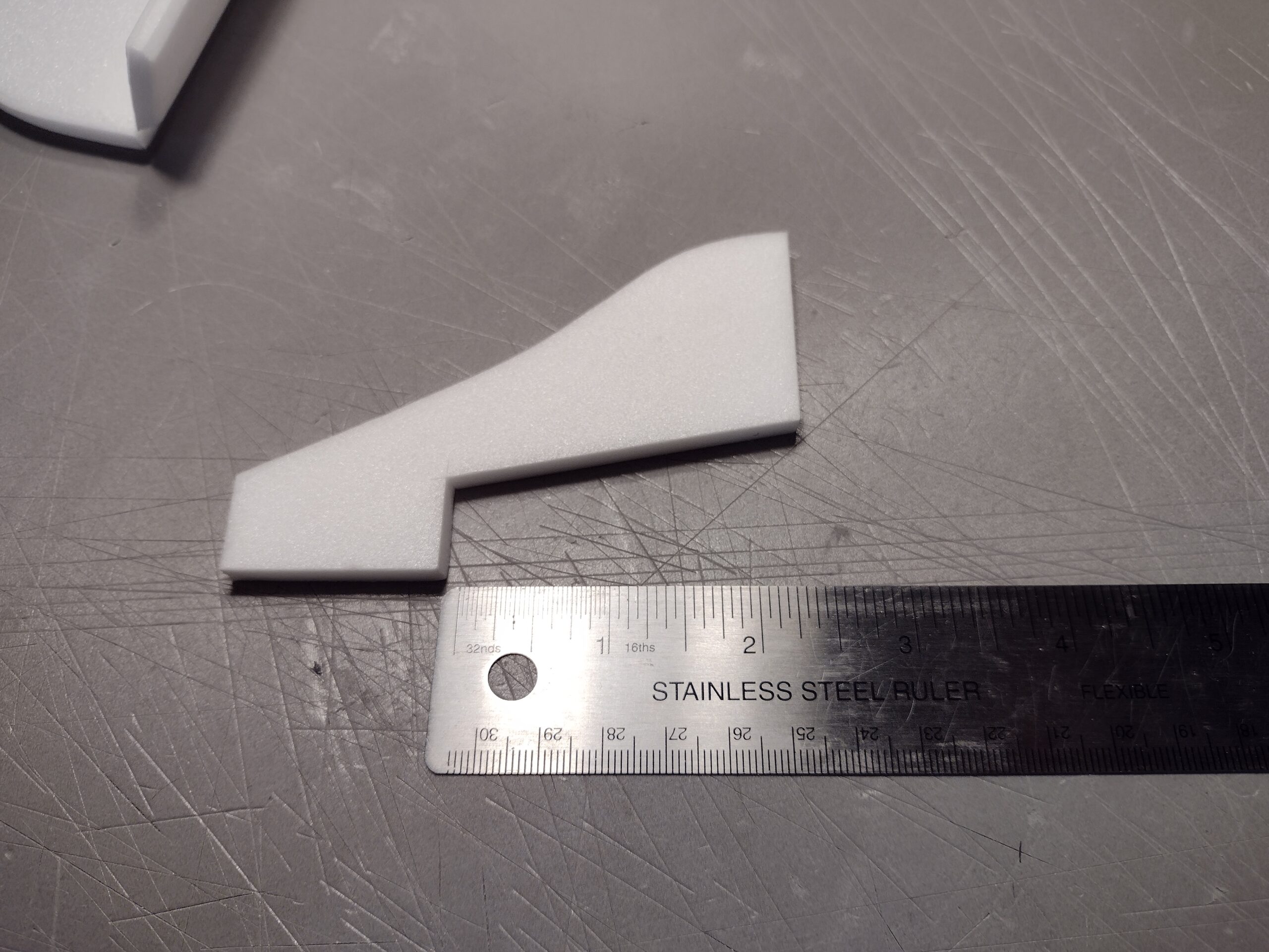
- Cut out a 1.5″ by 3/4″ or so section out of four of the nose pieces.
-
- Laminate the four pieces together
-
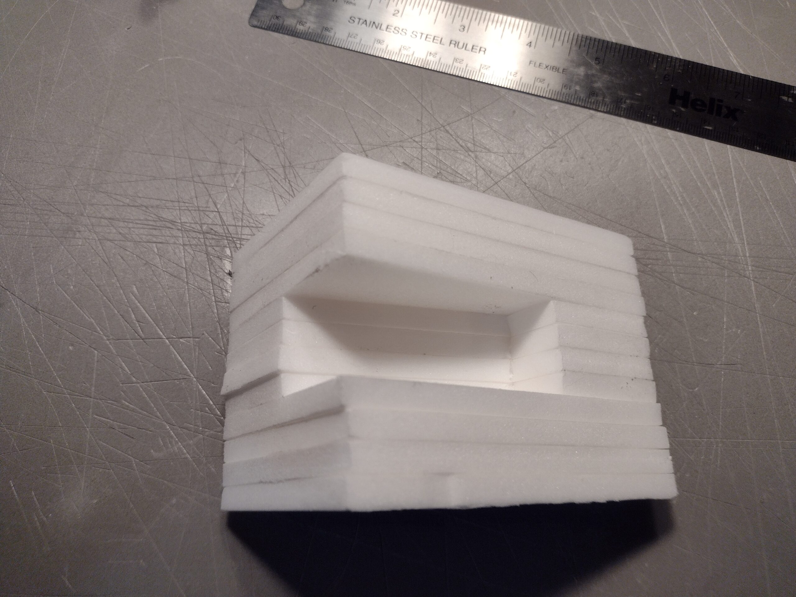
- Laminate the other nose pieces on either side to make a pocket for the nose weight and battery.
-
- Glue all the nose pieces together using 3m-77 spray adhesive.
-
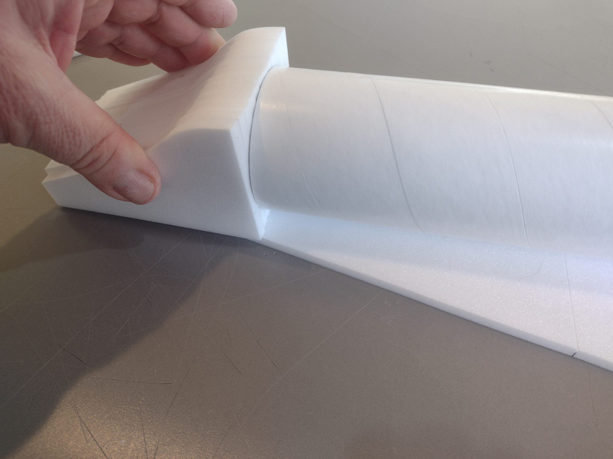
- Sand the bottom and rear of the nose assembly flat and then glue to the front of the wing centered on the body tube. DO NOT GLUE TO THE BODY TUBE!
-
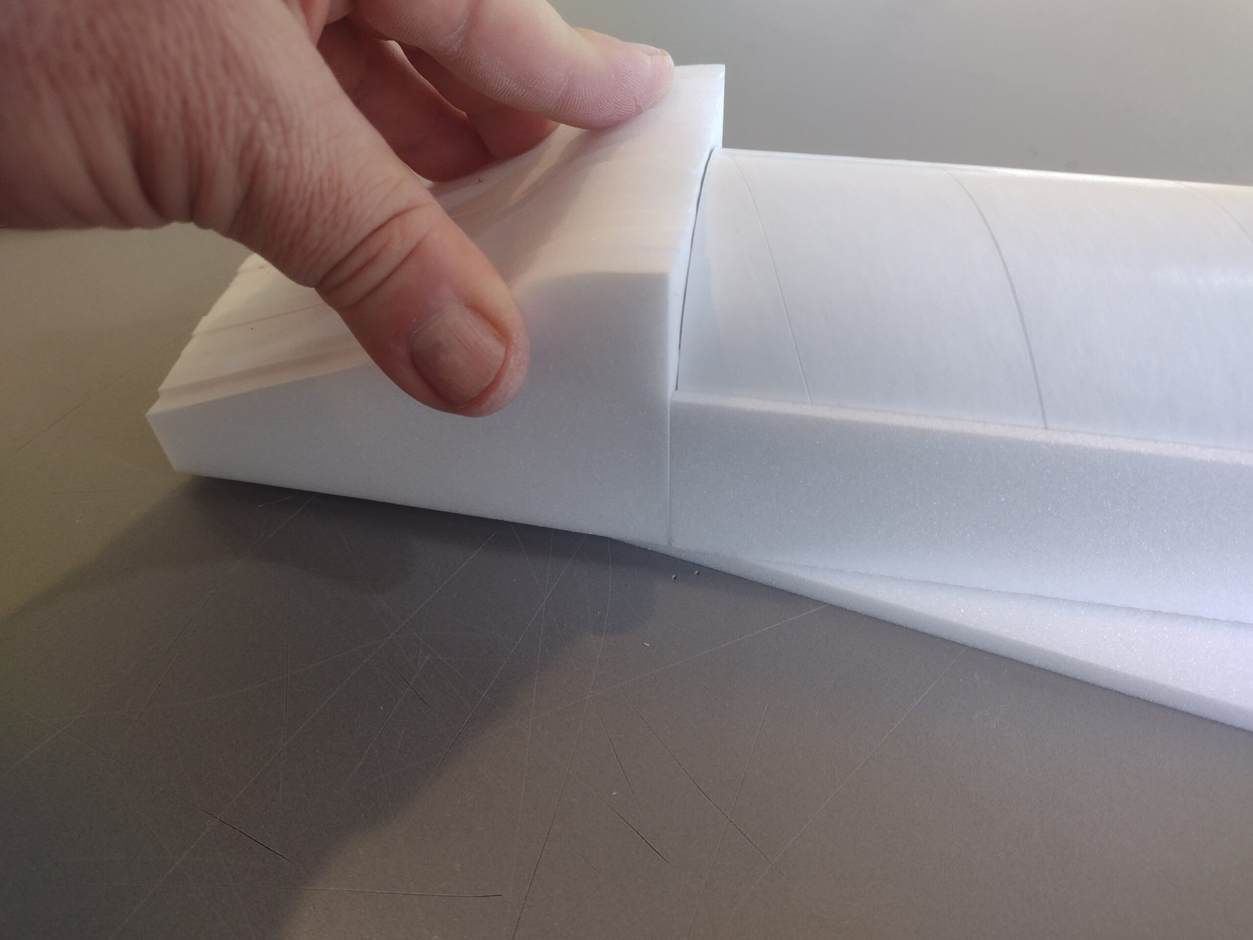
- Test fit side plates, see how they butt against the nose assembly at the front.
-
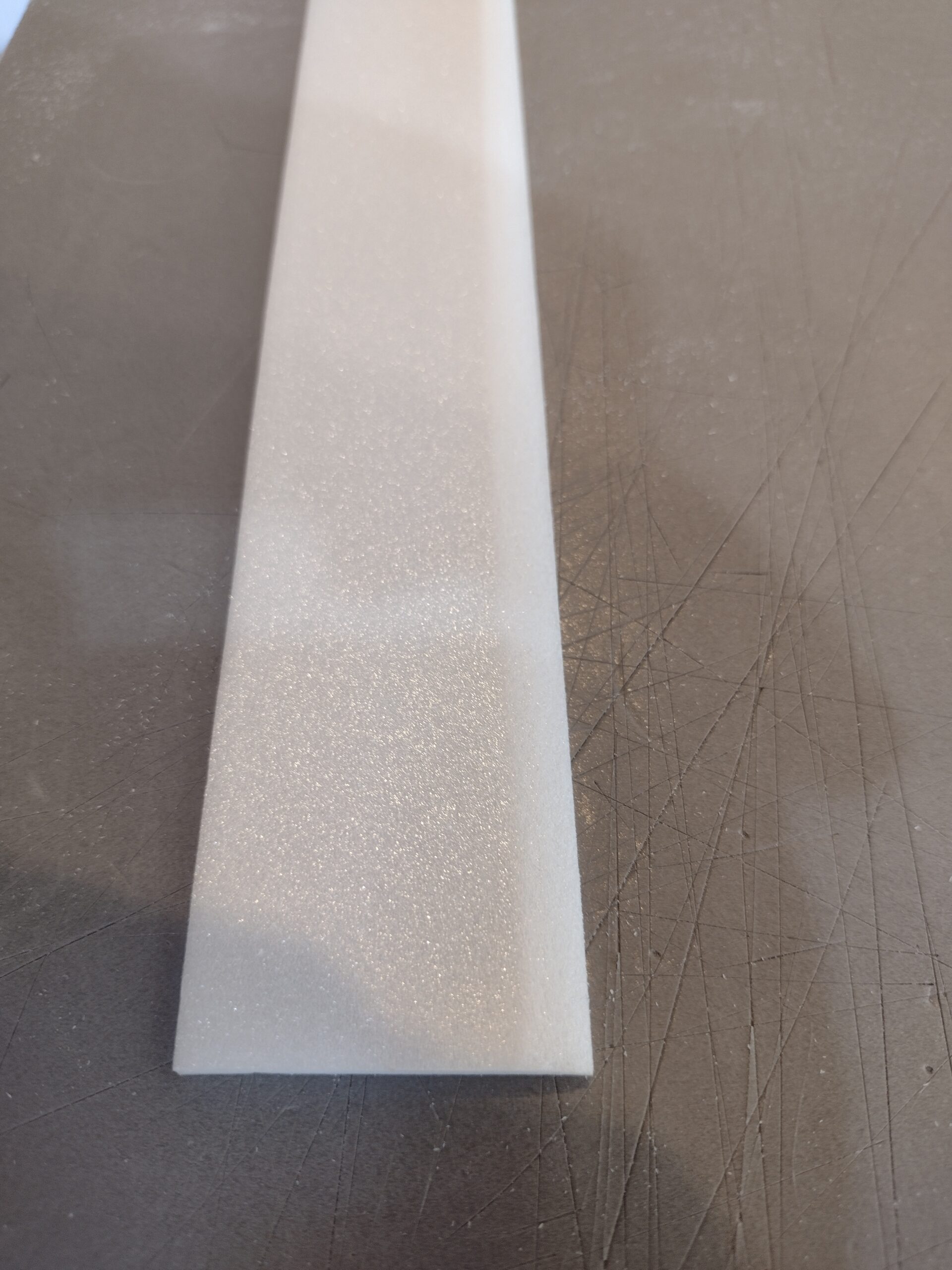
- Sand the top edge of each side plate to a beveled edge.
-
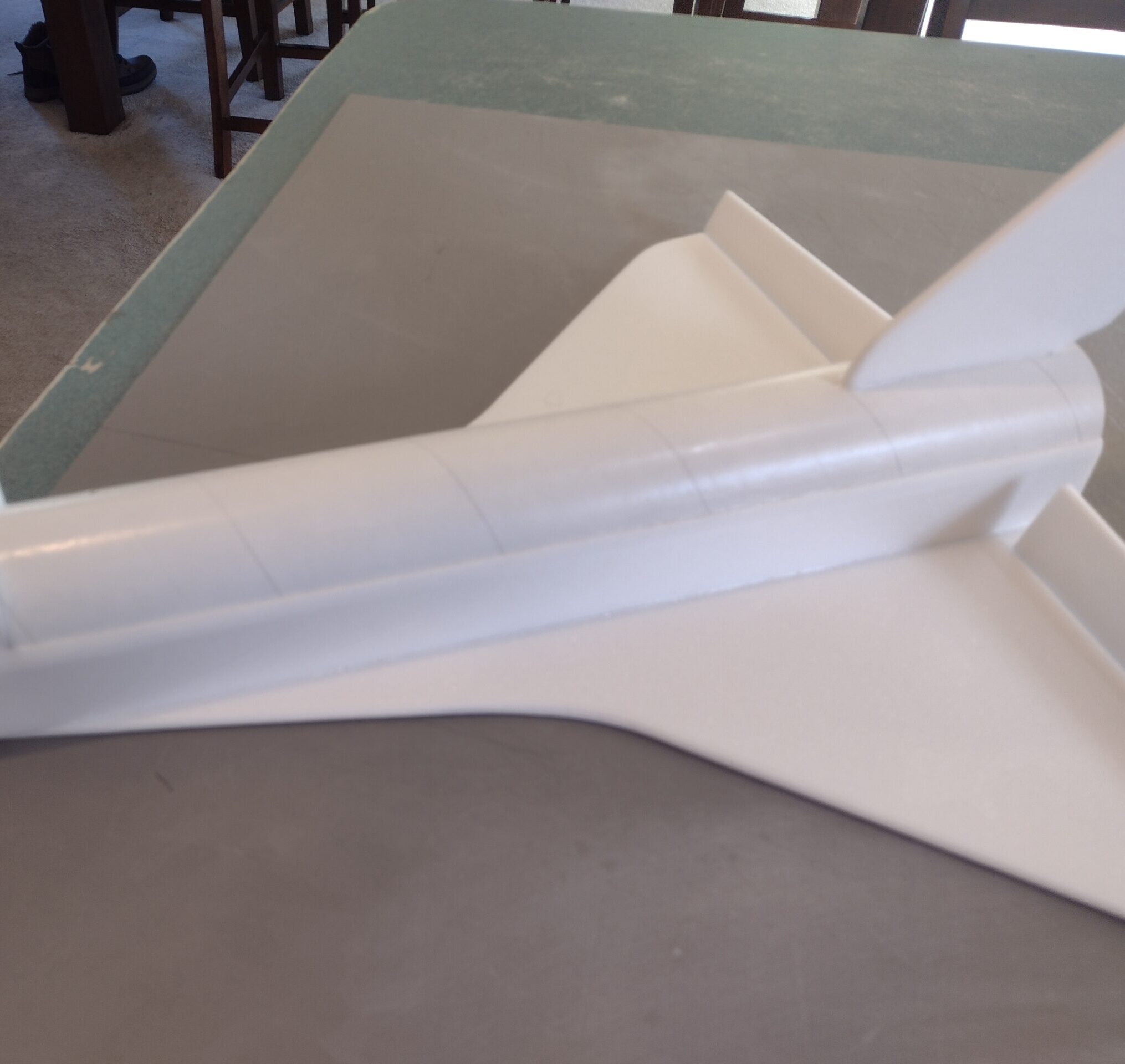
- Glue side plates even with rear of model and against the wing, tube and butting up against the nose section.
-
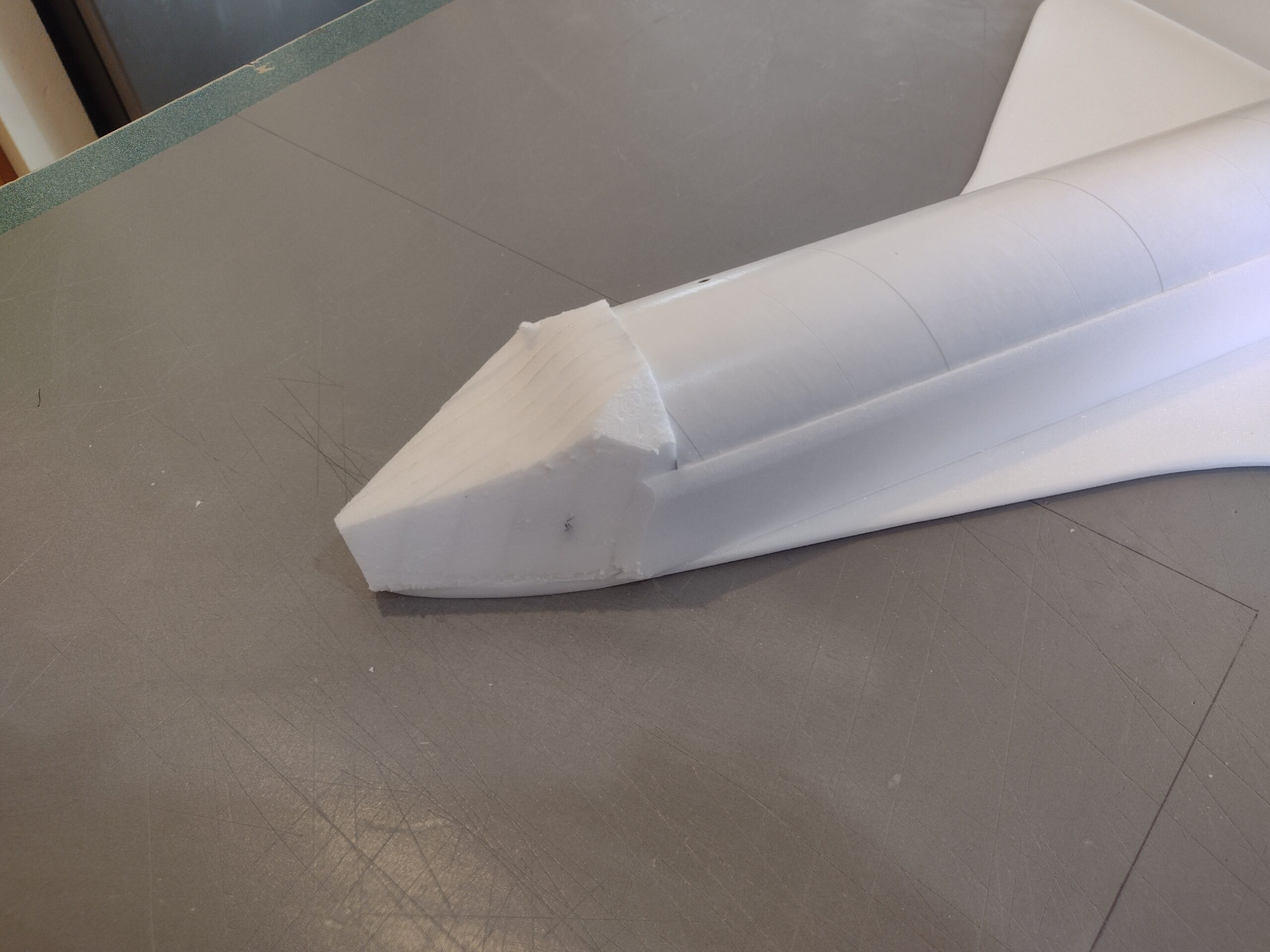
- Rough carve the nose to shape.
-
- Mask then sand the nose section to shape.
-
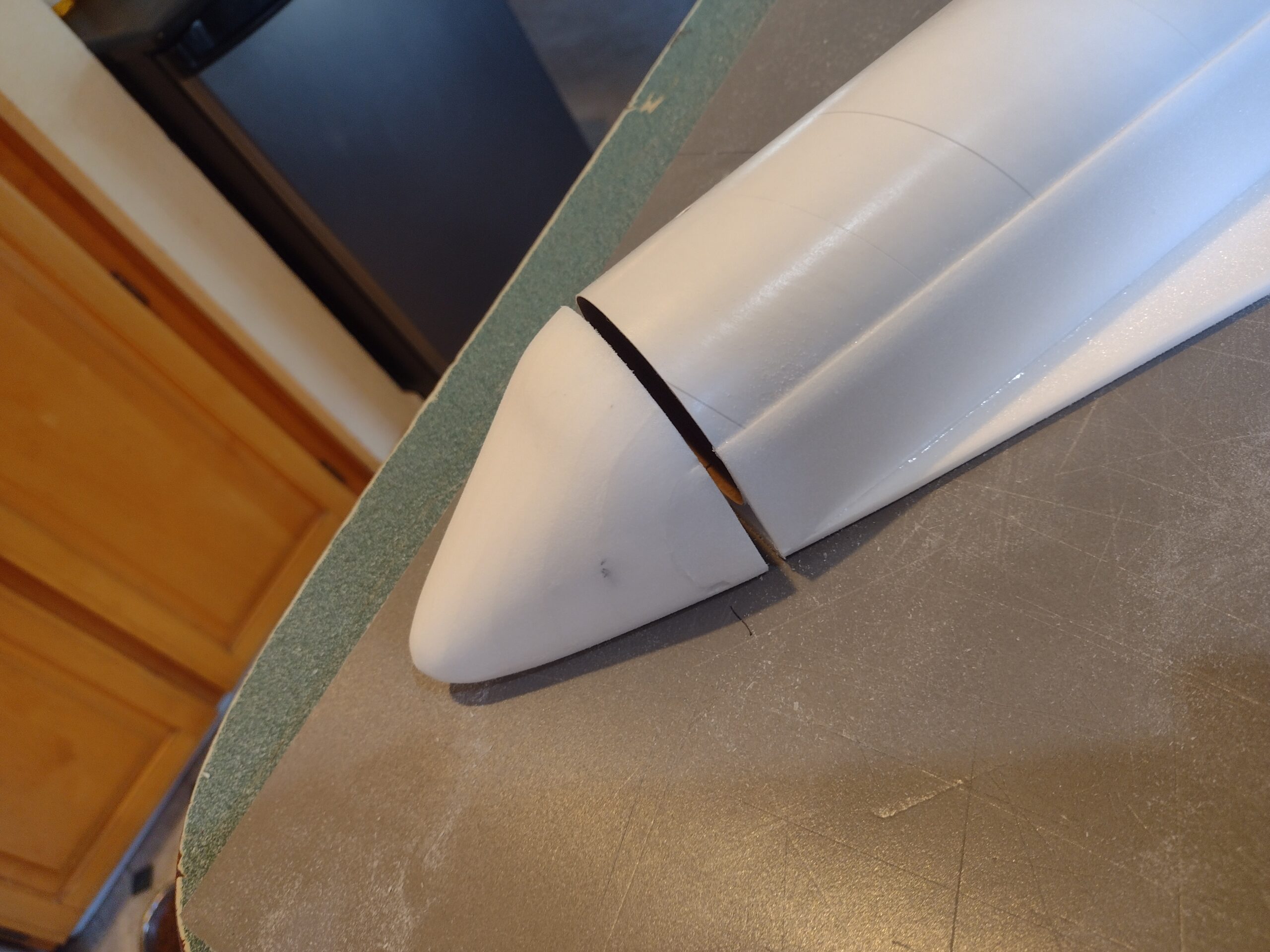
- cut the nose section by cutting the bottom of wing where the front of the body tube stops.
-
- Slide coupler partway into the body tube then tack glue the nose to the coupler so it will line up with the wing and tube when pushed in fully. DO NOT glue the coupler into the body tube!
-
- Remove the nose cone and apply a fillet of CA on the INSIDE only of the coupler to glue it well to the foam.
-
- fillet on the inside of the coupler.
-
- Glue a pushrod/horn into to the top of each elevon, note the rod is on the inside of the horn and angles indward.
-
- Apply glue on the prongs on the bottom of each horn.
-
- Airframe complete.
-
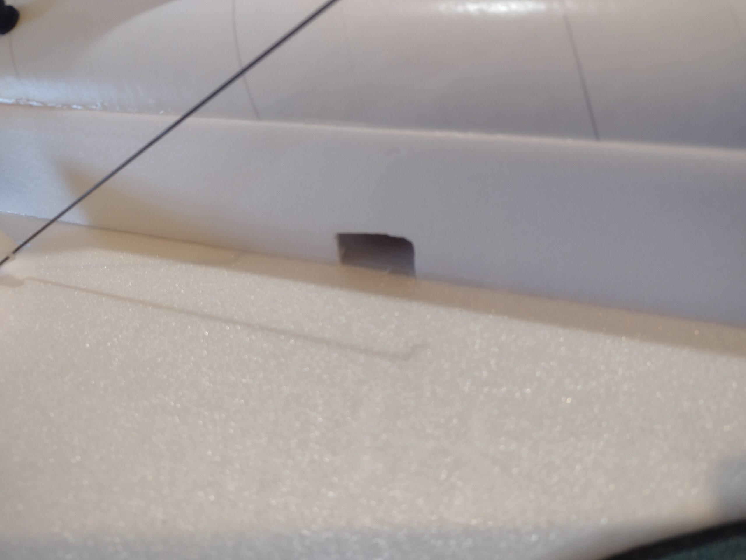
- Measure where the servo will go and cut a pocket into the side plate and the body tube through the hole in the side plate.
-
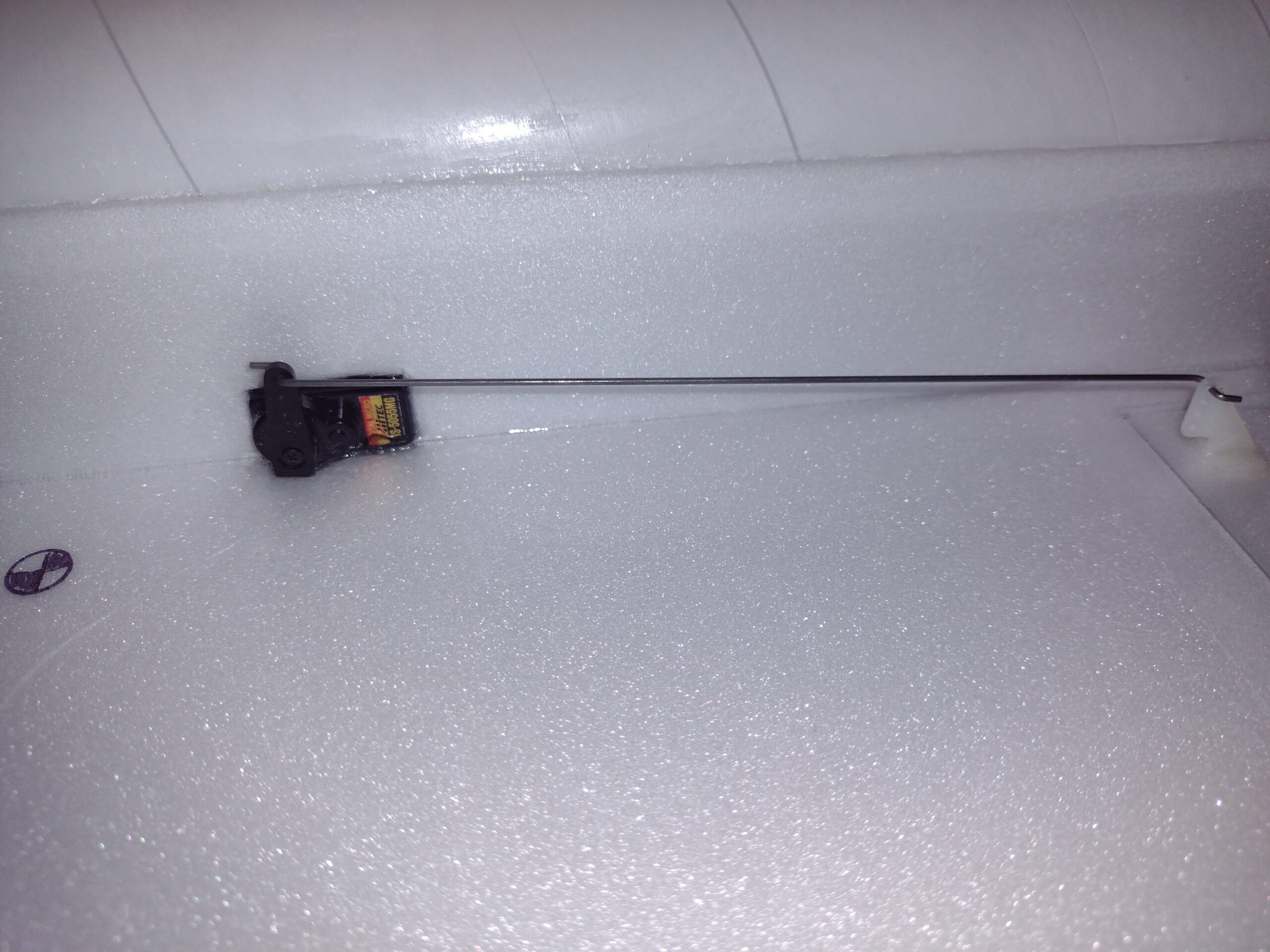
- Install each servo into the pocket you just cut.
-
- Route the servo wires out the back of the model, the servo wires need to go through the same quadrant of the motor mount so you can pass the receiver back up to the front when done. Power everything up and glue the servos in place keeping the elevons level.
-
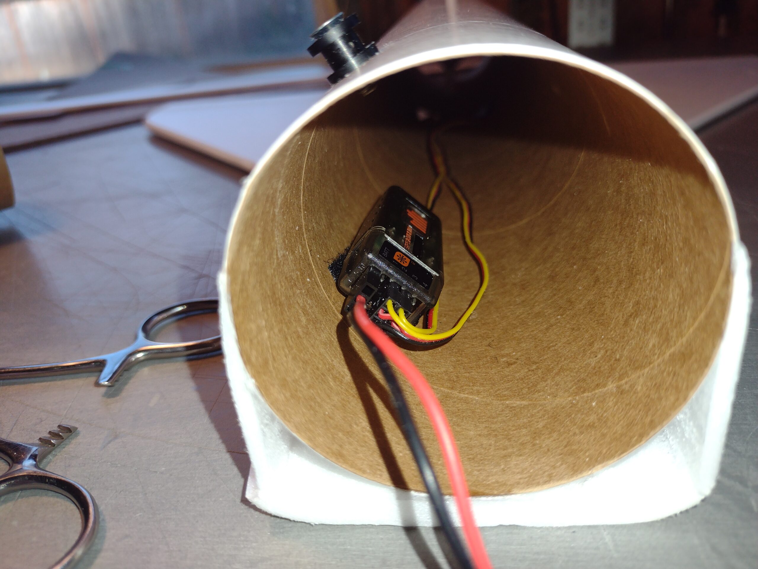
- Once servos are set and glued in place, route the receiver up to the front of the model and secure it in the body tube with provided velcro. In set it far enough that the coupler won’t hit it.
-

- Secure the battery into the hole melted in the nose cone with provided velcro.
-
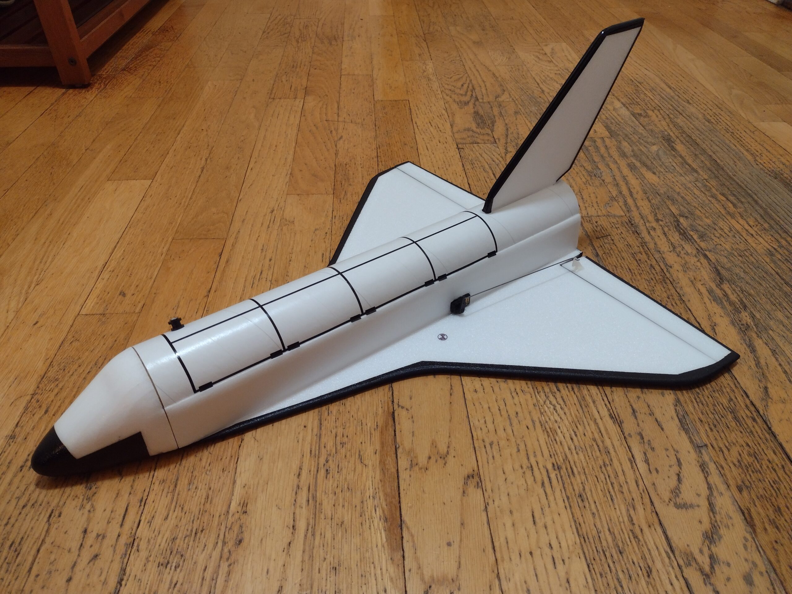
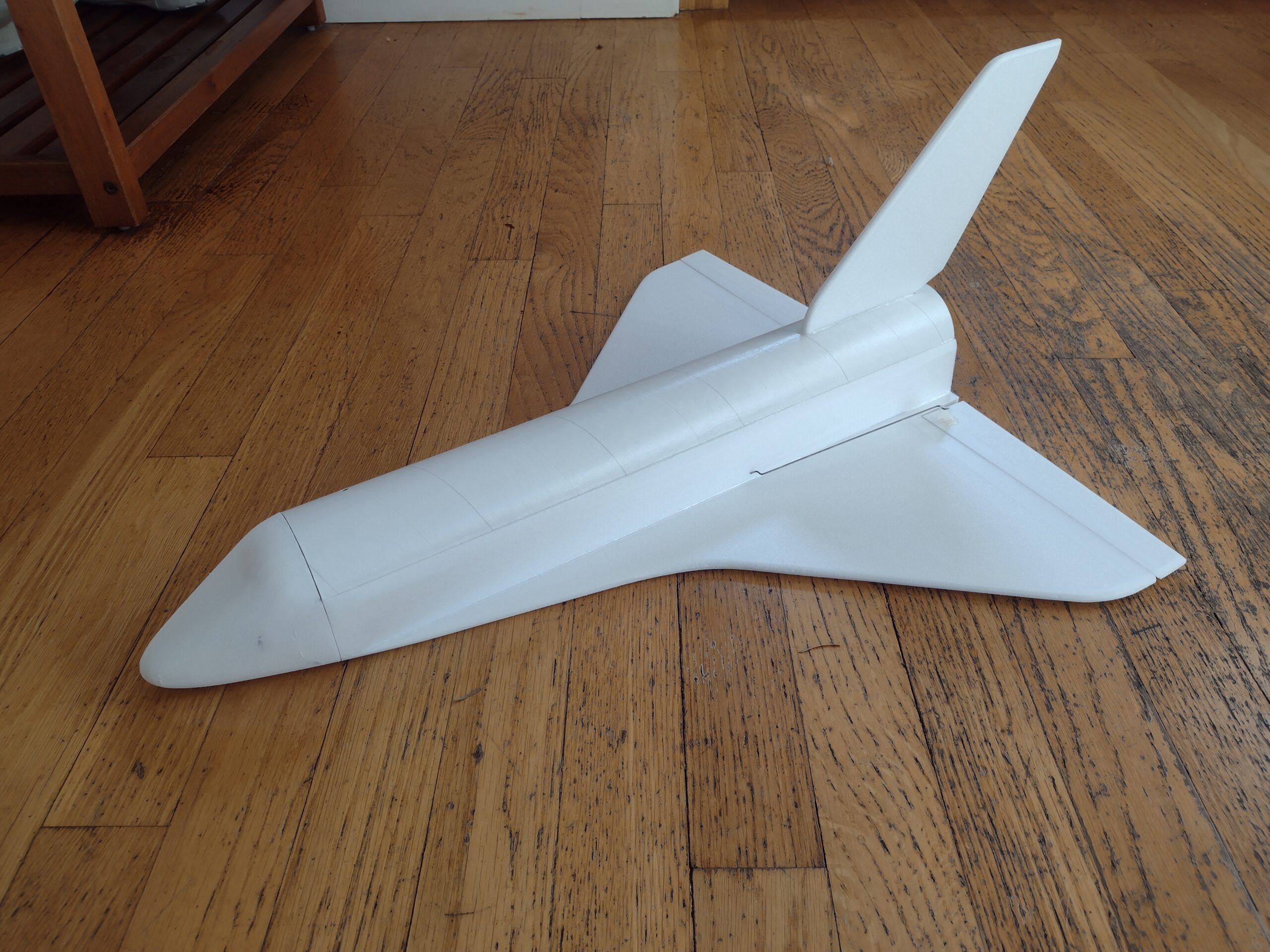
- Model after masking and painting the bottom/sides/top of wing and tail and some added trim tape for the payload doors and hinges.
-
- Completed model in Moonraker markings
-
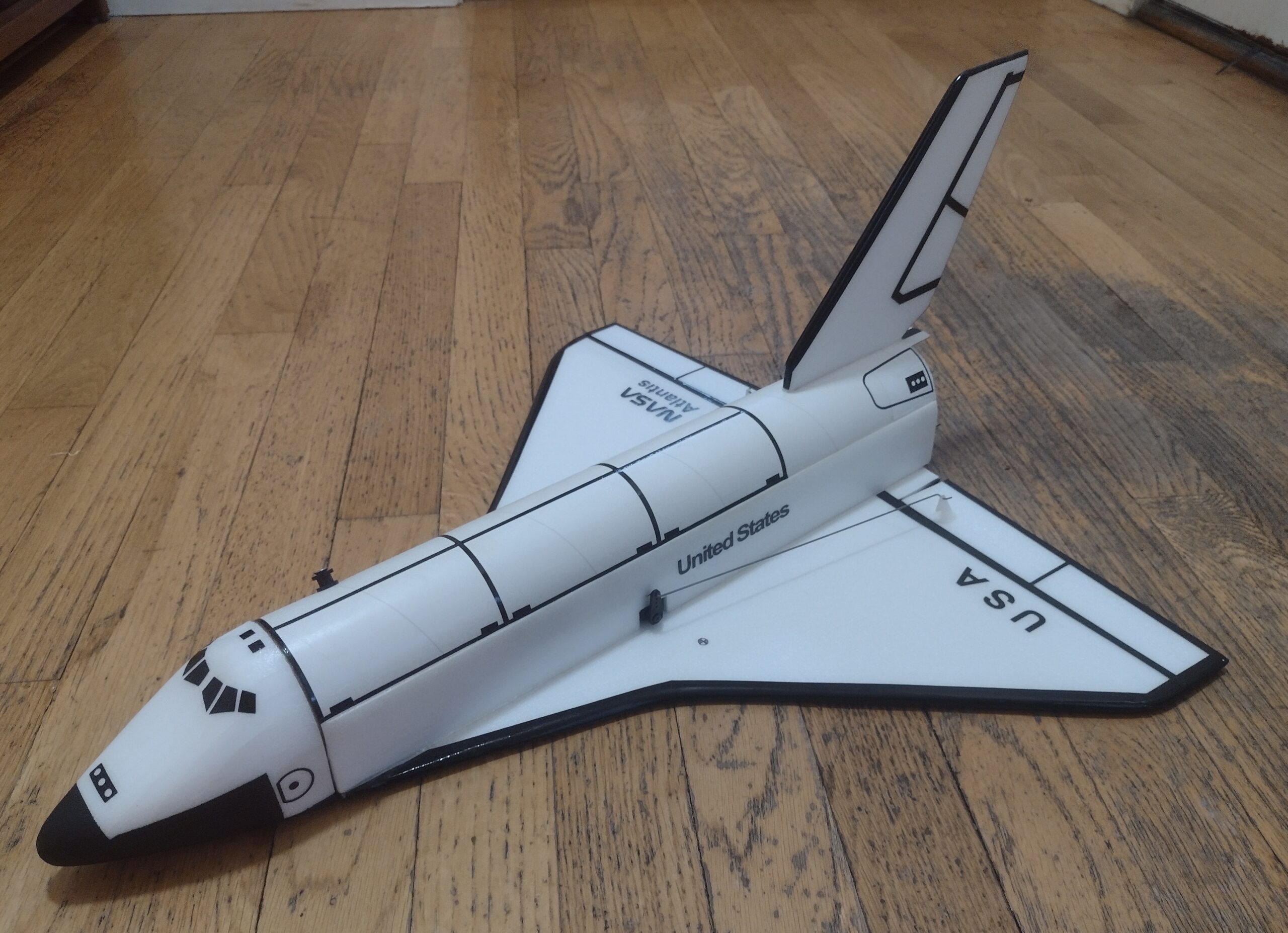
- Completed model in US markings
-
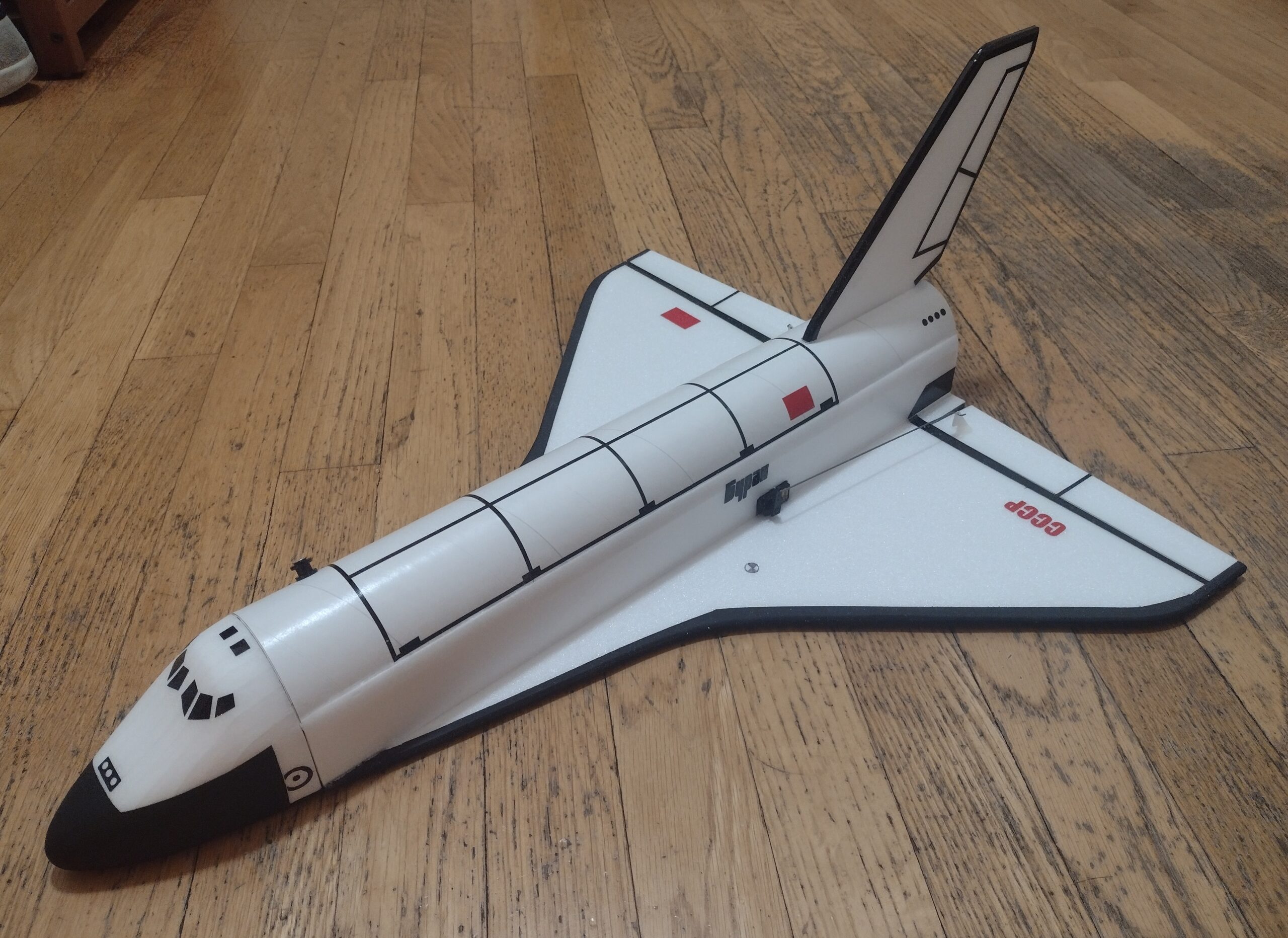
- Soviet Buran Markings
-
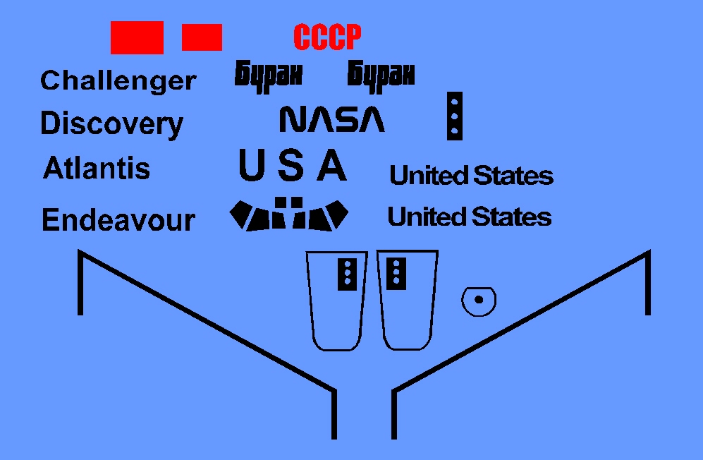
- Stickershock US/Buran Set
-
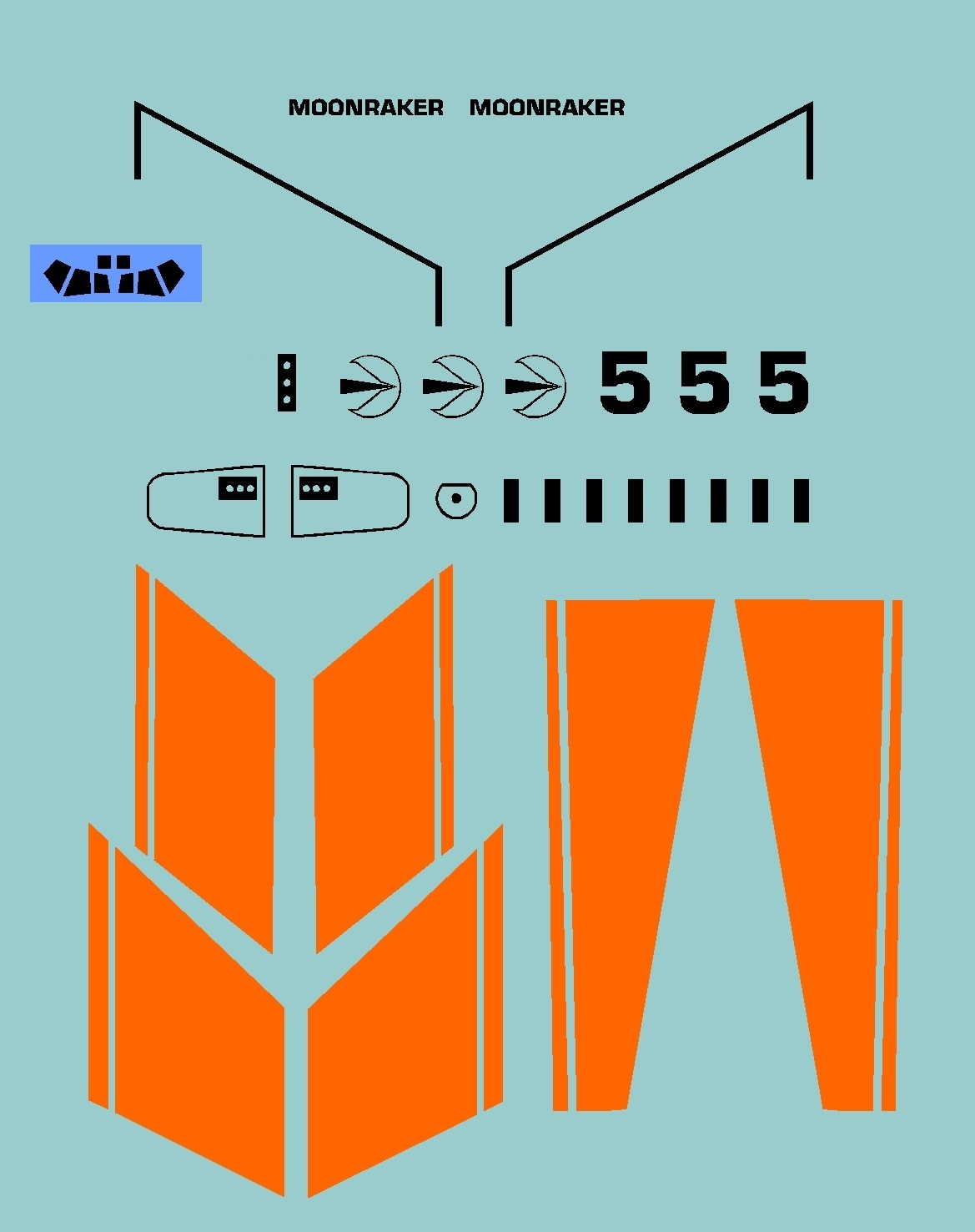
- Stickershock Moonraker Set