The Orbital Express 18mm RC Rocket glider kit is designed to be an orbital class vehicle that returns via glide recovery. It is a smaller version of our 24mm Orbital Express kit with added wingtips instead of a central stabilizer and reduced weight for 18mm motors. It comes with a plastic nose cone, white tubing for the body, and 6mm depron wing and tail surfaces. The body tube has the rail button holes are pre-punched. Elevons are pre-hinged and spar is pre-installed. Construction and radio install is very simple. 19.6″ wingspan, 22″ length, 40mm” diameter, 5.3 oz ready to fly. For 18mm Reloadable D2.3T and C3.4T composite rocket motors only. Please refer to the General information for all kits tab above, then read these instructions completely before starting assembly. On my model I used these decals, he prints them on white, but you can ask him to print on clear as well, available HERE:https://stickershock23.com/product/estes-space-shuttle-1284/
The CG is 8 1/4″ forward of the rear of the wing with motor and battery installed ready to fly.
Identify all pieces, the kit should contain:
1 wing taped together
1 Nose Cone
2 pushrods/horns
2 vertical stabilizers
1 body tube
18mm Motor mount
2 6mm x 2.75″ angle cut foam strips to reinforce the motor tube glue joint.
Velcro(for battery and rx/bec attachment)
2 Rail buttons with t nuts/screws
Lead weight
Spare foam (for testing paint, glue, and sanding the edges to see how it behaves)
Notes before starting:
Foam safe CA+(Bob smith super gold + is good) is the only glue recommended for construction. You will also need foam safe accellerator to set the glue.
Assembly:
- Glue the taped wing joint and lay flat to set.
- Bevel cut the leading and trailing edges of the both sides of the wing and outside edge only of the stabilizers with a straight edge and exacto knife, just a small 1/16″ to 1/8″ is fine. Make a left and right stabilizer.
- Install the front and rear rail buttons at this time in the pre-punched holes in the body tube. The t-nut goes on the inside, then add a washer, collar and washer and secure with a screw.
- Apply a 1/2″ squiggle of glue to the wing line on the bottom of the body tube and on the wing centerline, then lay the body tube on the top of the wing and make sure the front and rear alignment lines are lined up with the center of the wing at the front and back. The wing trailing edge is flush with the rear of the body tube. The rear of the body tube has the line inside the tube for the motor mount. Make sure the wing is not rolled left or right and tape the front and rear of the wing in place and lay rightside up and press down lightly on the tube till the glue is set. Wick some drops of glue every inch or so into the joint on both sides to make sure your glue joint is strong and wait till it is set.
- Glue the motor tube into the inside bottom of the body tube on the line marked. Look at the front of the body tube and make sure it is relatively straight and not rolled to one side or the other. When cured wick a little glue into the joints and let set.
- Glue one of the 2.75″ angle cut foam strips on each side of the motor tube. Put glue on the wide flat portion and insert next to the motor tube and make sure it touches the tube lightly. Once set apply a fillet of glue against the foam tab and the motor tube to reinforce the joint.
- Glue the vertical stabilizers against the sides of each wingtip, they are angled in on purpose, make sure the beveled edge is on the outside of the stabilizer(remember you made a right and left?)
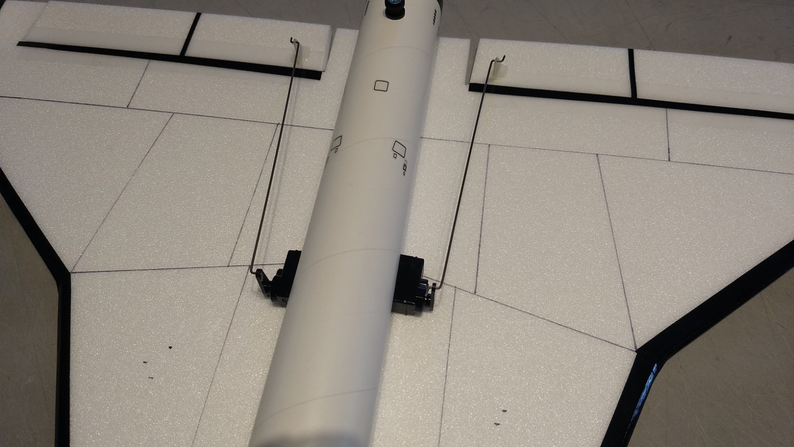
- Apply CA+ to each of the control horns and press them in place in the top of each control surface into the pre-made holes. Note the pushrods will angle inward toward the body tube, there is a left and right.
- Apply glue to the prongs on the bottom of the wing to lock the horns in place.
The basic construction is now complete.
Radio Installation
Note: Your radio needs to be configured for Delta mixing, this means that the servo arms will move the same direction during elevator stick movement and opposite for aileron stick movement. Connect your servos to the receiver one in the aileron connection and one on the elevator connection and apply power. Use a servo arm at least 9/16” long and with holes small enough that there won’t be slop with the pushrod wire when installed. I use the hole furthest out on the servo arm, to maximize movement. On some servos there are a long two-ended servo arm, you can trim off one end if needed to get sufficient length. Zero out any trim settings on the transmitter. The model once the motor has burned out is nose heavy and flying wings lose pitch authority when nose heavy so you want as much up elevator travel for trim/flare as possible.
- Connect a servo to each pushrod. If the pushrod is too tight, you can use twist an X-Acto knife in the servo arm hole to make it larger, but be careful and do not make it too large. Once connected, tape each servo in place so that the control surfaces are centered. Look at the model from the rear. Moving the transmitter stick back(up elevator) should move both elevons up. Moving the transmitter stick to the right should move the right elevon up and the left elevon down. If you can’t get the servo reversing to give you the right polarity try swapping aileron/elevator inputs to the receiver or turning the servos over and swapping the servo arms to the other side of the output shaft. If that is correct, continue.
- The servos are attached by directly gluing the servo to the wing with foam safe CA+.
- Mark where the servo will be when the control surface is neutral and cut a pocket into the body tube so that the servo is inset slightly. Repeat on the other side. To save weight, I removed the case on my receiver, then connected each servo to the receiver and pushed the receiver through one of the servo pockets forward so that the battery wire will reach the end of the body tube and re-connect the battery. Alternately you can attach a very short lightweight servo extension to each servo then route the wire into the notches on each side and out the front and re-connect the servos to the receiver and re-connect the battery. You may need tail weight to balance if you chose this method.
- With the radio still on, put a moderate amount of glue on the servo, being careful not to get any near the output shaft, and set it in place on the wing in the pocket you just cut, keeping the control surface centered. Do the same to the other side. Make sure the glue is set before continuing. If you need to adjust the pushrod by bending the angle at the control arm so the servo is not angled, simply do so with a needle nose pliers before gluing the servo in place.
- Make sure the control surfaces are centered, use trims if needed. Now measure the control surface movement. Full elevator movement should be 1/2” in each direction, aileron movement should be 3/8″ in each direction. Since the model will be nose heavy, extra elevon movement helps to give sufficient authority during glide.
- If you have a flap/elevator mix you can program up elevator to a switch setting. The model needs approximately 1/4″ of up trim for glide. If you can’t set the up elevator trim to a switch on your radio you’ll have to manually put in boost and glide trim which is hard to do while flying the model. You can also use flight modes to set different launch and glide elevator trim settings and control those via a switch.
- I can only recommend testors/model master enamel spray or Krylon Short Cuts small enamel spray cans at this time, others I’ve tried damage the foam surface. I recommend flat colors as they dry faster and the surface imperfections of foam aren’t as noticable. I left the body tube and top of the wing bare(no paint to save weight) I painted the nose cone flat gray then when dry masked off and painted the bottom of the wing and nose cone flat black. I then masked/hand brushed the leading edges of the wing/tail. Balance the model after painting as it adds weight. Use the pictures as a rough guide for painting.
- I used a fine line sharpie to add some panel line accents.
- If you use the stickershock decals, It helps once applied to heat them with a hot hair dryer and press them down into the foam surfaces to really get them to conform/set. Do NOT use a clearcoat over the foam surfaces!
- Install your receiver inside the nose cone and tape in place for now.
- Install your battery in the bottom of the nose cone and tape in place for now.
- Insert your heaviest loaded rocket motor into the motor mount
- Support the model at the balance point indicated for boost. I use two pencils with the eraser pointed up and held in place with a small hand vice. Place the model upside down on the pencil erasers on the balance point indicated above.
- Adjust the battery placement and see if you can get it to balance without adding weight. You can shift it forward into the nose or back into the body tube as required. Use velcro to permanently mount it in place. I taped the battery wire down inside the body tube to hold the receiver from moving. If you left the case on you can use velcro on the case to hold it in place. I had my battery held in place about 1″ back from the end of the body tube using velcro.
- If necessary use some of the included lead weight as far forward into the tip of the nose to balance it, or in the tail as needed. Glue the lead weight in place so it does not shift during flight. Do not try to fly the model too nose or tail heavy. Remember, a nose heavy model flies poorly, a tail heavy model flies once. My model did not need any nose weight for correct balance.
Flying: See the General Instruction link at the top for flying instructions. Be ready on the first few flights to keep the model straight till you have the trims set perfectly for boost and glide.
-
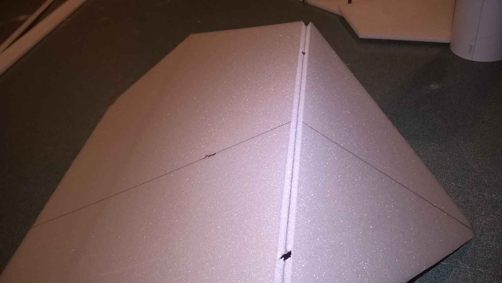
- Unfold wing and glue taped joint
-
- Wing unfolded and layed flat to dry
-
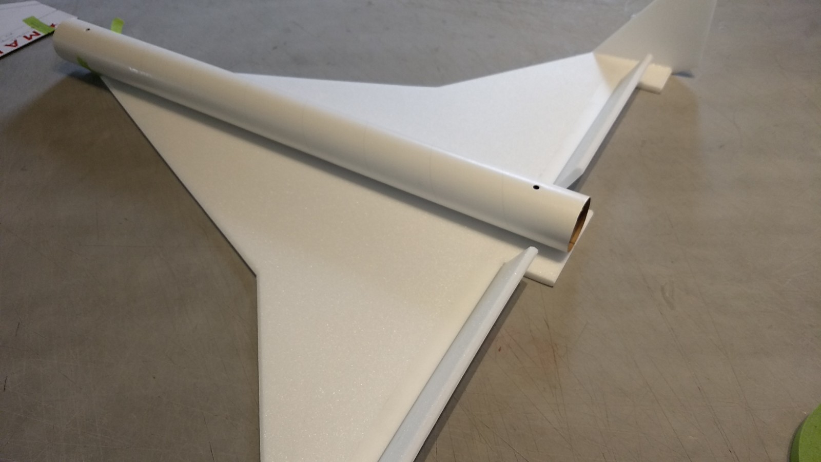
- Body tube glued to wing
-
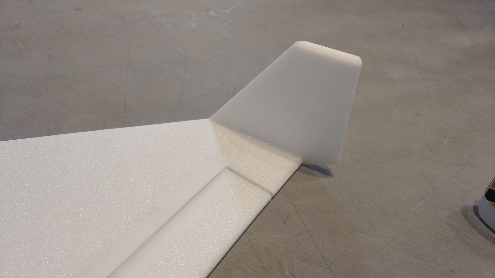
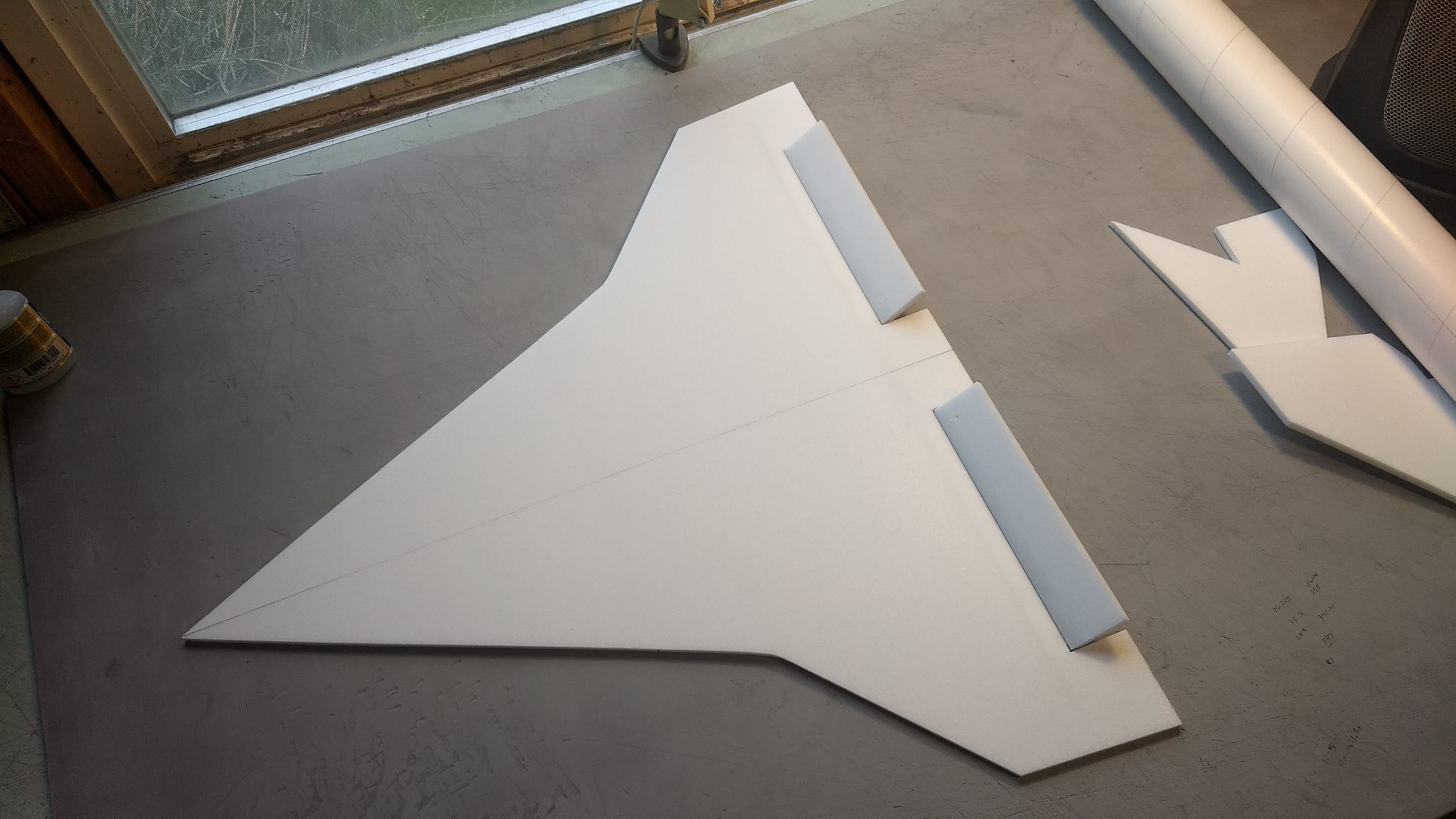
- Tip stabilizer glued to end of wingtip.
-
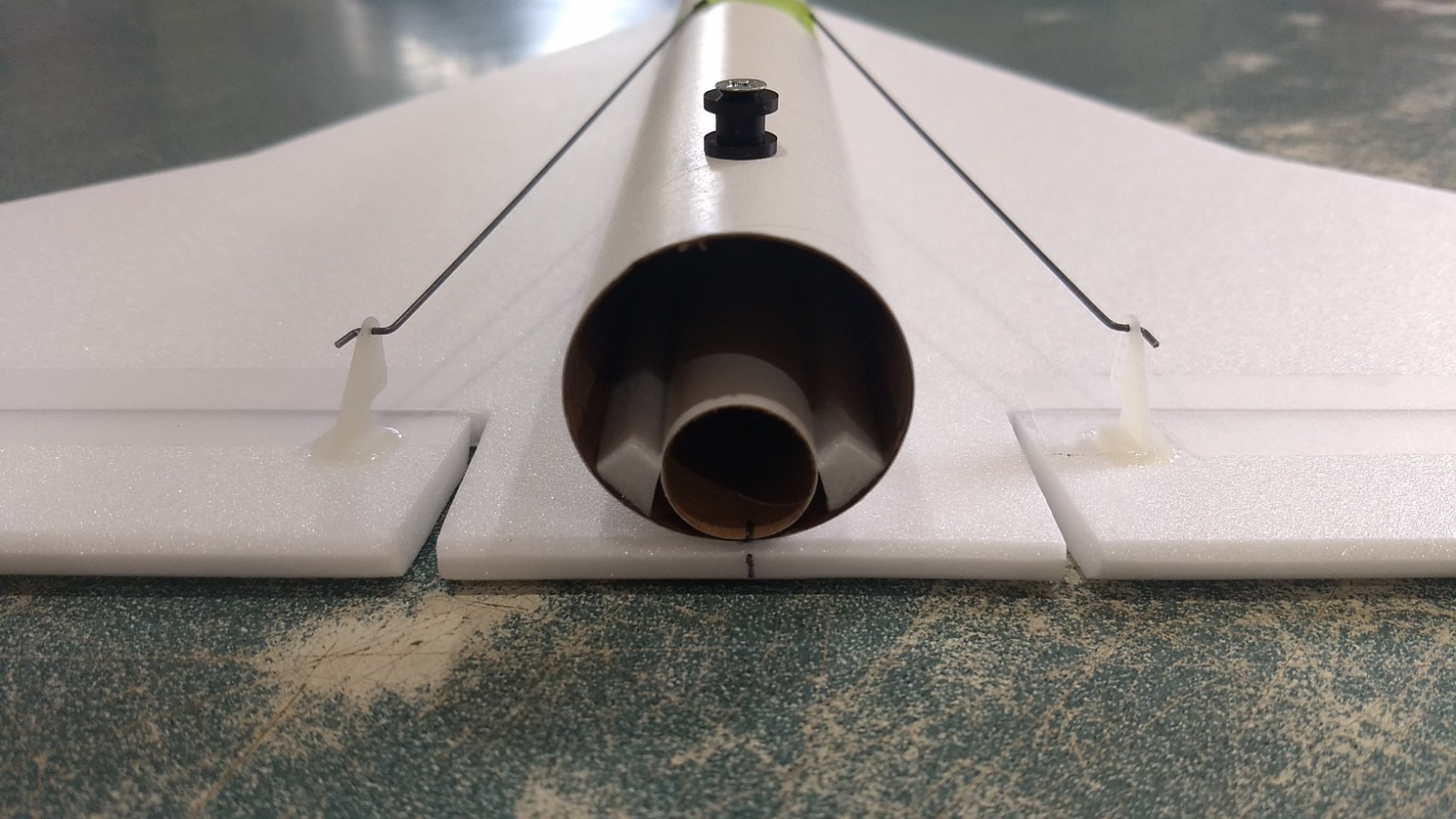
- Rail buttons installed front and back, then motor tube glued in place with beveled support strips on either side.
-
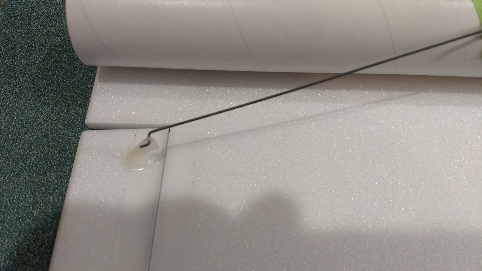
- Servo horn glued into top of control surface.
-
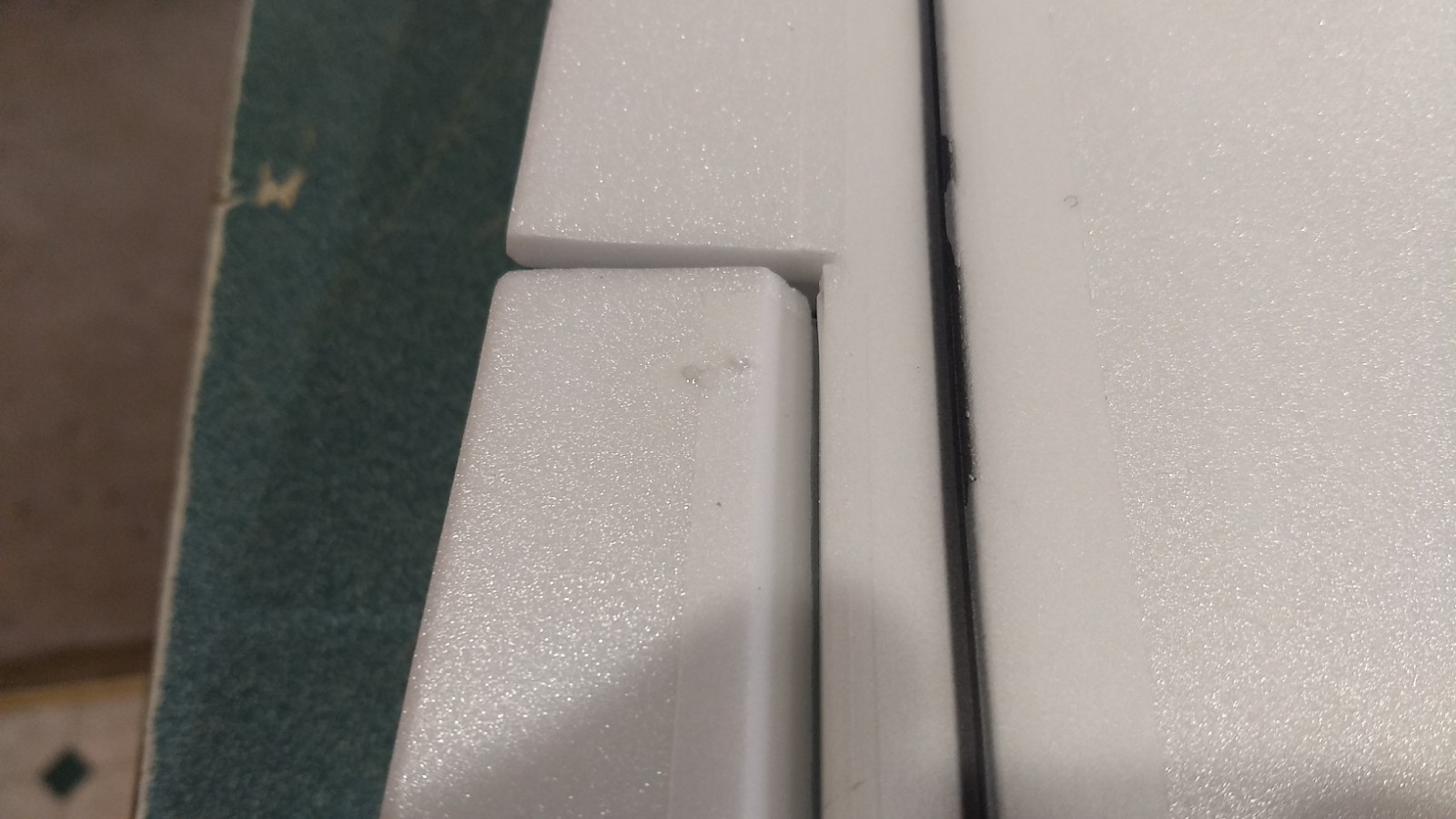
- glue applied to prongs of horn to lock them in place.
-
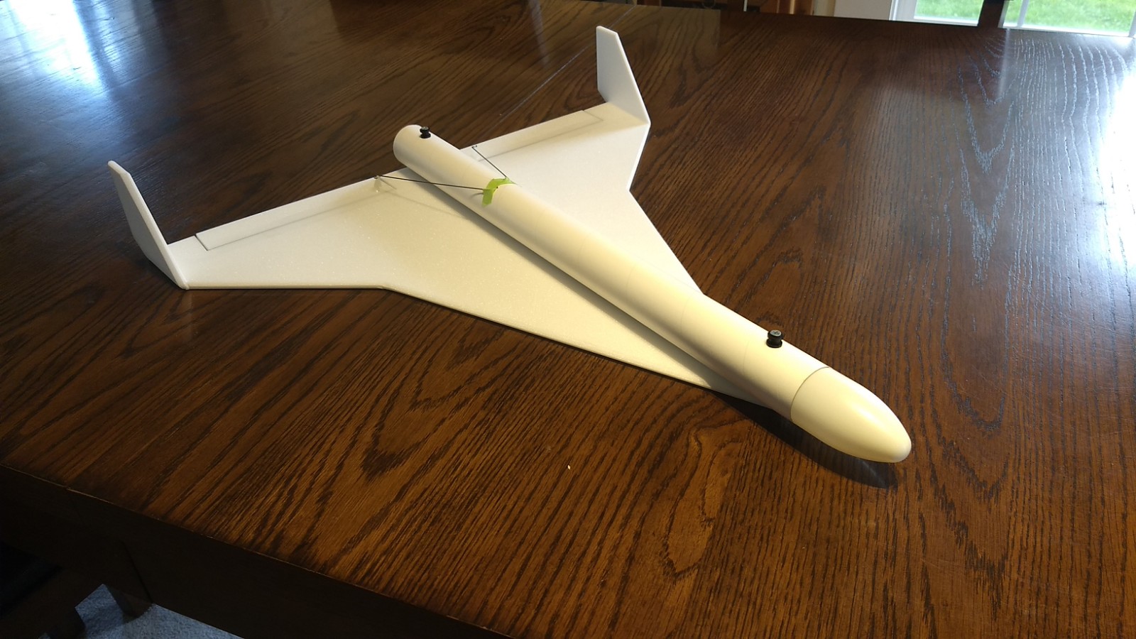
- Completed Airframe
-
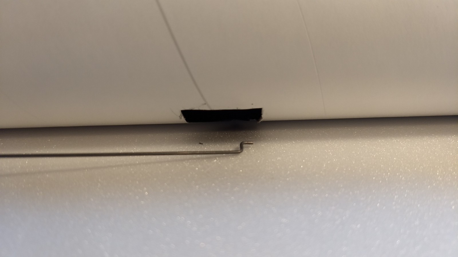
- Servo pocket cut in body tube.
-
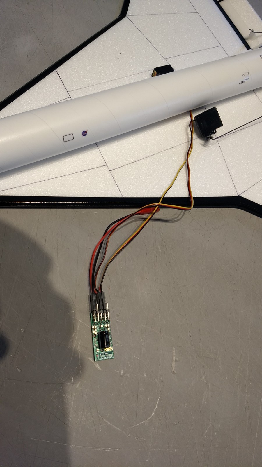
- Connect servos through cutouts to receiver with case removed.
-
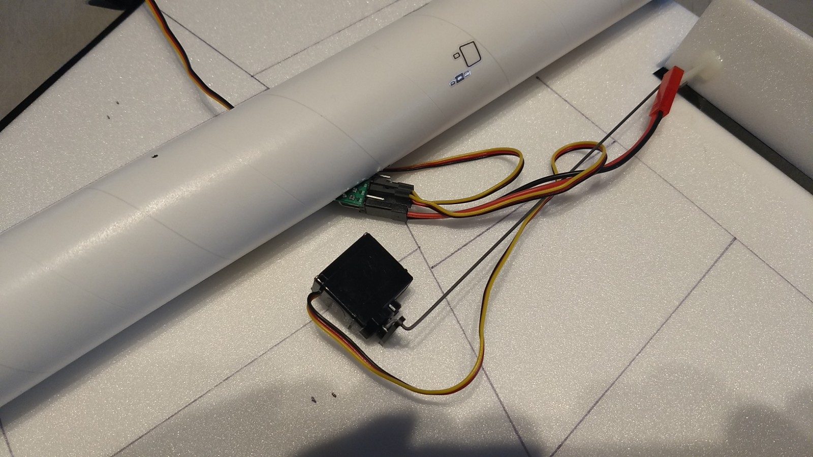
- Feed receiver, battery and wires into servo pockets.
-
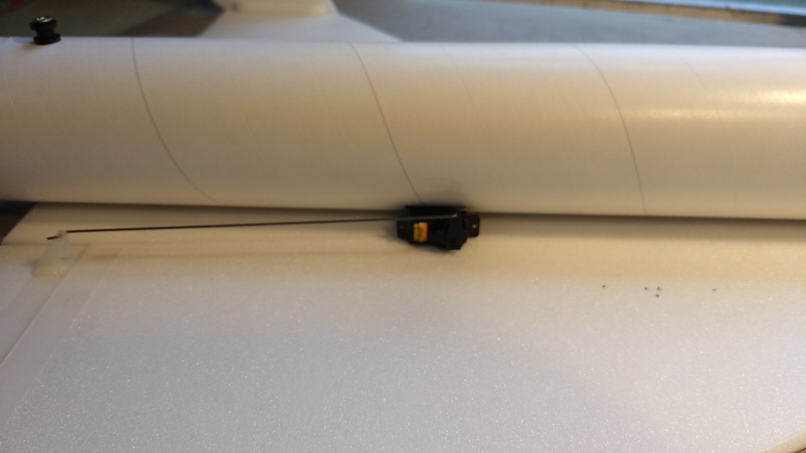
- Servos installed and glued into pocket.
-
- Servos Installed
-
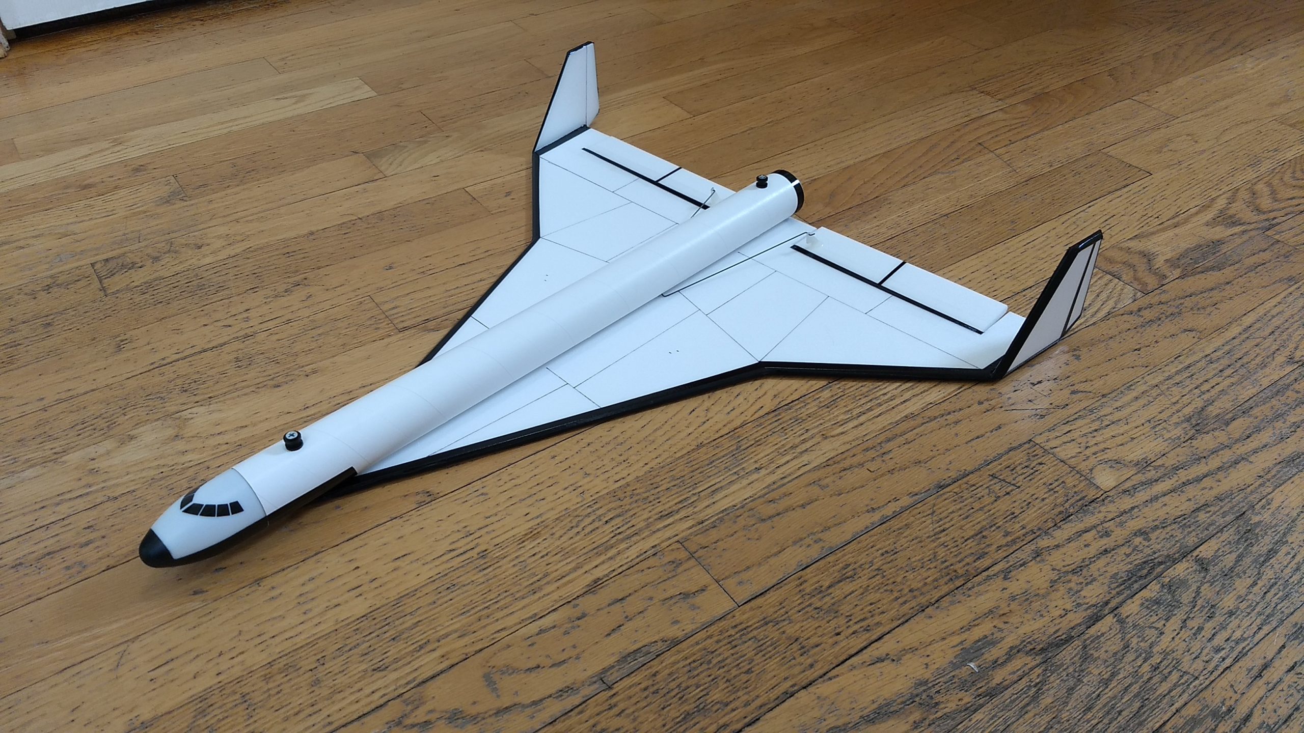
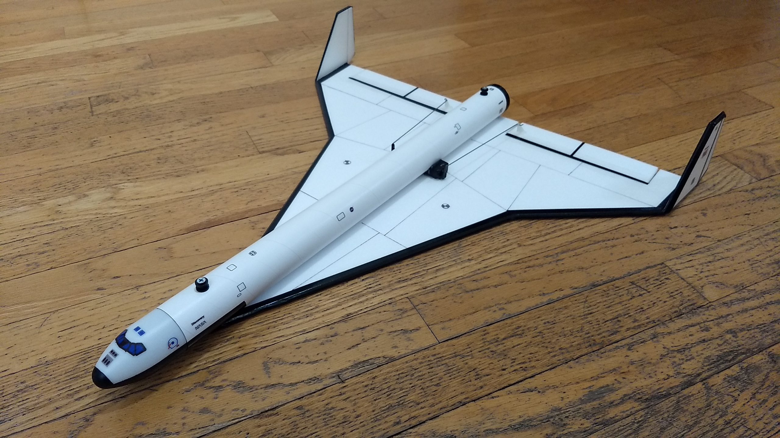
- Completed Model with generic markings.
-
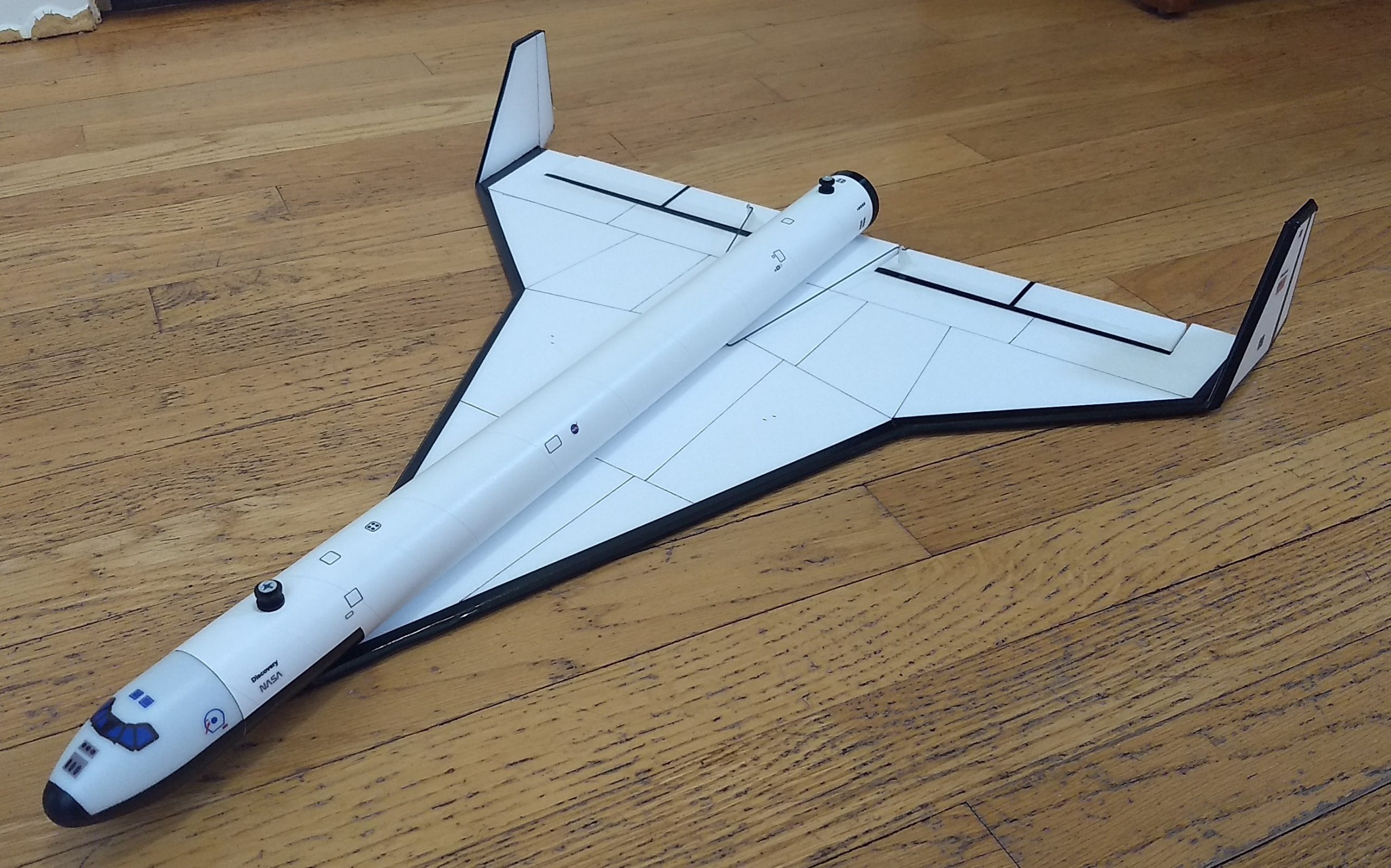
- Completed model with stickershock decals
-
- Completed Model ready to fly
-
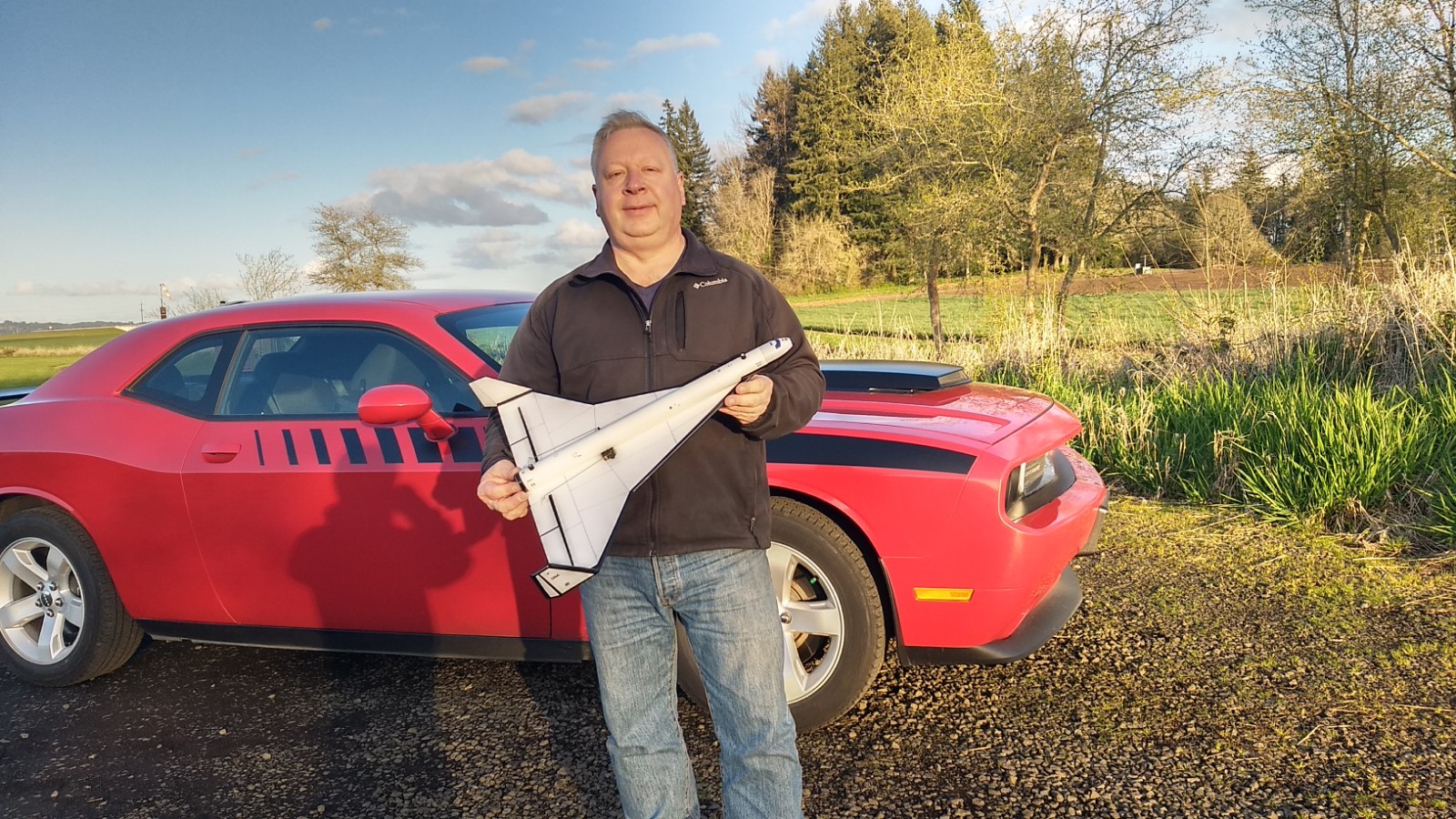
- Ready for maiden flight.