These instructions are for experienced R/C rocket glider folks that want to try converting the Estes #1250 Interceptor kit to an 18mm R/C rocket glider. This model is designed to be ultra light weight for the size and only use composite D-2.3 or C3.4 Aerotech reloadable motors.
This is a short kit meaning you will need to provide your own Estes Interceptor kit of which you will use the Body tube, centering rings, motor tube, nose cone and possibly decals. The rest of the parts won’t be used because they add additional weight which is not desired for this model to glide. The short kit will provide all other materials needed other than glue, finishing materials. You will provide your own 1s 500mah lipo battery, 6-9 gram receiver and 2 8-9 gram servos. I used HS-5055 metal gear digital servos and an AR-410 receiver with the case removed.
(Note if you already have an interceptor nose cone, or if you want to 3-d print one, you can find one here, just make sure the weight is not more than 14 grams or you will be nose heavy) You just need an 18mm motor tube, two centering rings to BT-55(CR2055F) and an 18″ length of BT-55 tubing)
Due to the large size of the wing and tail surfaces and the fact that the water slide decals won’t stick well to the foam, cut vinyl decal sets that will fit this model shown are available HERE Chose the small 18mm set They include the stars/bars, text, cockpit and tail markings. You can use the kit decals on the nose and body tube if desired. Specs: 25″ length, 15″ wingspan, 5.1 oz rtf, for 18mm reloadable D2.3 and C3.4 Aerotech composite motors.
CG location for rocket flight: Right at the intersection where the strake hits the wing leading edge. This should be measured with a loaded rocket motor and battery installed as you would be ready to launch the model.
Please refer to the General Information Link above then read the instructions completely before starting assembly. The assembly photos are for general reference but may not include every step in the instructions. If you want hardcopy to work from, all you have to do is click/drag/select and copy all of the text below, open word and paste with “keep original format” and it looks exactly like it does online then you can print it.
Interceptor Rocket glider instructions:
Short Kit Parts:
Wing
2 Vertical Stabs
Carbon Spar
1 rolls of 1″ wide 3m blenderm tape
Self adhesive Velcro(for battery and rx/bec attachment)
2 Rail buttons with t nuts/screws
Lead weight(not needed in most cases)
Adapter wire to adapt a small 1s 500mah lipo battery or similar to the receiver for power.
2 control pushrods with horns.
Notes before starting:
Reference to glue, CA, or CA+ means foam safe CA+, normal CA+ will melt the foam! Normally you need to use accelerator to get the CA to set on the foam since there is nothing for it to soak into and activate.
I bevel the edges of the foam surfaces before assembly which helps reduce drag and makes the model look nicer. I simply use a sharp Xacto knife and a metal straight edge to cut a 1/16-3/32″ wide 45 degree bevel on the edges. If you decide to sand the edges, use a block and a VERY light touch and do small areas at a time to avoid the paper catching the foam and tearing it. Do any shaping before assembly.
Epoxy is not needed in this model. It is designed to be assembled ONLY with Bob Smith foam safe medium thick CA+ and accellerator or equivalent. Weight is critical and the model is designed for the thrust and flight loads. Weight in the rear end is bad and will require additional weight in the front of the model.
Assembly:
- Unfold the wing and glue the taped joint, lay flat to dry
- Test fit the spar and then glue it into the groove and tape over with blenderm tape.
- Glue the two kit centering rings 3/4″ from each end of the motor mount tube.
- Use the kit provided marking guide to mark the wing lines and upper stab lines as well as the bottom for the rail buttons.
- The slots for the stabs will be 1″ from the rear of the tube forward the length of the tab on the fin, use the fin to determine the length, the width will be cut to just fit the foam, take your time and make multiple passes till you cut through, test fit and adjust as needed. I use a piece of angle aluminum to cut the lines and supported the tube inside with a piece of 29mm motor tube split lengthwise and slipped over another piece of 29mm motor tube which fit inside perfectly, if you have an 18″ length of bt-55 coupler that works well and is available from balsa machining as are the 29mm motor tubes.
- The slots for the wings will be 3.5″ from the rear of the tube forward to the length of the wing, use your wing to measure the exact length and the width will be the width of the foam. Take your time and make multiple passes till you cut through, test fit and adjust as needed.
- The rail button holes can be cut with an exacto knife about 1/8″ in diameter or slightly larger. The rear button hole should be 4″ from the rear of the tube, the front about 1.5″ from the front of the tube.
- Test fit the motor tube in the rear of the model, mark the front centering ring where the two vertical stab slots are so you can trim these to clear the stab tabs later on.
- At this time I covered my body tube in self adhesive white vinyl and then cut out where the slots and holes are. Alternately you can paint the tube white and let dry. I do not recommend painting the white foam except for the wingtip pods to save weight.
- Install the rail buttons. This must be done before installing the wing and motor mount. For the rear button I set the t-nut on the end of a table knife and slide it into the tube and press up so it pops through the hole, you can hold it in place till you screw the rail button down. The t-nuts are pre-bent to help them confirm to the small diameter tube, make sure the bend is not rotated so the t-nut is flush on the inside and won’t deform the tube.
- Test fit then install the wing into the body tube. The visible spar should be down. Make sure it is centered and glue in place with a light fillet of foam safe CA on both sides top and bottom.
- Test fit then install the vertical stabs into their slots. The angle isn’t critical just make sure they are about the same on each side. Apply a fillet of glue on the inside and outside of the tube/fin/tab joints.
- Trim out notches in the front centering ring where you marked it from the fin tabs and test fit, it should insert till the rear centering ring hits the rear of the fin tabs. Glue in place by applying a fillet of glue on the rear centering ring, the fin tabs prevent it from moving forward and there is little stress in this area.
- Using a dremmel cutoff wheel or razor saw cut the bottom of the nose cone shoulder so that it is open and approximately 3/4″ long, this reduces nose weight and allows you to insert the battery into the nose for proper CG.
- Test fit then glue the wing tip pods centered on the left and right wing tips top and bottom, try to keep the aligned with each other top and bottom, then sand the ends to a pleasing shape.
- The nose cone can be painted with any gloss white paint, tamiya laquer is good.
- The wing tips can be painted after masking using testors flat or gloss red enamel small rattle can or krylon short cuts small can paint. These will not damage the foam. I don’t recommend any other paints.
- Glue the two pushrods/control horns into the bottom of each control surface, there is a left and right, the pushrod should be closest to the model and angle inward toward the body tube slightly. Apply glue on the top of the horn prongs to lock the horn in place.
The basic construction is now complete.
Radio Installation
Note: Your radio needs to be configured for Delta mixing, this means that the servo arms will move the same direction during elevator stick movement and opposite for aileron stick movement. Connect your servos to the receiver one in the aileron connection and one on the elevator connection and apply power. Use a servo arm at least 9/16” long and with holes small enough that there won’t be slop with the pushrod wire when installed. I use the hole furthest out on the servo arm, to maximize movement. On some servos there are a long two-ended servo arm, you can trim off one end if needed to get sufficient length. Zero out any trim settings on the transmitter. The model once the motor has burned out is nose heavy and flying wings lose pitch authority when nose heavy so you want as much up elevator travel for trim/flare as possible.
- Connect a servo to each pushrod. If the pushrod is too tight, you can use twist an exacto knife in the servo arm hole to make it larger, but be careful and do not make it too large. Once connected, tape each servo in place so that the control surfaces are centered. Moving the transmitter stick back(up elevator) should move both elevons up. Moving the transmitter stick to the right should move the right elevon up and the left elevon down. If you can’t get the servo reversing to give you the right polarity try swapping aileron/elevator inputs to the receiver or turning the servos over and swapping the servo arms to the other side of the output shaft. If that is correct, continue.
- I taped my control surfaces level with the wing for this next step.
- Mark the body tube where each servo will be inset and cut a pocket to recess the servo. The servos will butt against each other.
- Route the servo wires forward and reconnect them to the receiver.
- Keeping the radio powered up make sure the elevons remain centered and glue each servo against the wing and into the pocket in the body tube. Adjust the pocket as needed to try to keep the surfaces level.
- Make sure the control surfaces are centered, use trims if needed. Now measure the control surface movement. Full elevator movement should be 3/8” to 1/2″ in each direction(I used 125% dual rate), aileron movement should be 1/4″ to 5/16″ in either direction(I used 100% dual rate). Since the model will be nose heavy, extra elevon movement helps to give sufficient authority during glide.
- If you have a flap/elevator mix you can program up elevator to a switch setting. The model needs approximately 1/4” of up elevon during glide. Alternatively if you have flight modes you can set up flight modes so that trim is unique to each mode, that way you can pre-set boost and glide trim for each mode using the xmitter trim tabs. If you can’t set the up elevator trim to a switch on your radio you’ll have to manually put in boost and glide trim which is hard to do while flying the model.
- I removed the casing from the receiver(see video in the general instruction page on how to do this) Then pushed the receiver back above the wing and taped the adapter wire inside the body tube to keep the receiver from moving around. I did this to save 3 grams of weight. You can see if you can balance the model with the casing on and then just slide the receiver above the wing and tape the wire down as well.
- I attached my battery so that the rear was about 1/2″ inside the nose cone shoulder using the supplied velcro. You may tape the battery in place till you balance the model before deciding where the velcro will go.
- I used some spare trim vinyl to add the accents on the leading edges of the wing used a hot hair dryer to soften them and push them down into the foam for a secure set. If you use the decals from stickershock you can do the same thing after they are applied to set them.
- Insert your heaviest loaded rocket motor into the motor mount
- Support the model upside down at the balance point indicated for boost. Move the battery forward or backward as needed, my model needed no nose weight. Glue lead weight in the nose or tail as needed to balance it as a last resort. Do not try to fly the model with it balancing it behind this point. The adage is, a nose heavy model flies poorly, a tail heavy model flies once.
Flying: See the General Information link at the top for flying instructions. Be ready on the first few flights to keep the model straight till you have the trims set perfectly for boost and glide.
-
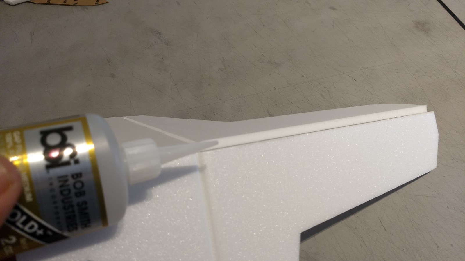
- Glue taped wing joint
-
- Glue spar and tape over with blenderm tape
-
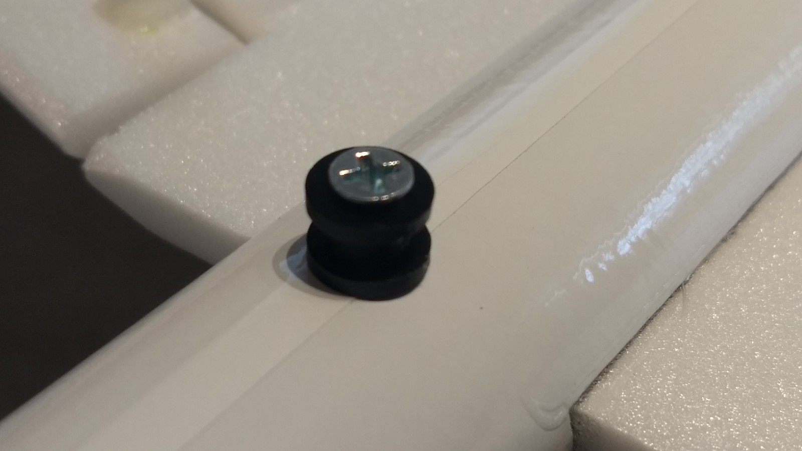
- Rail buttons installed
-
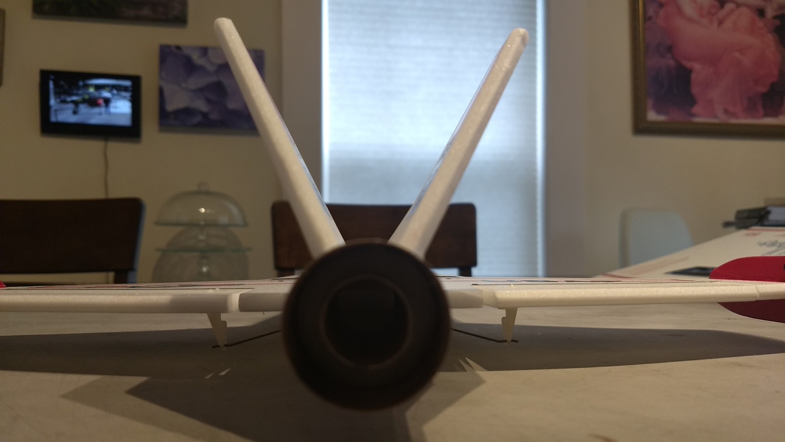
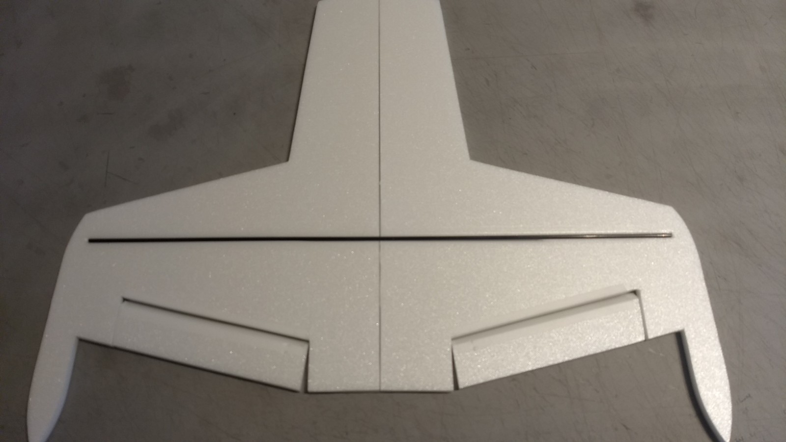
- Stabs and wing installed
-
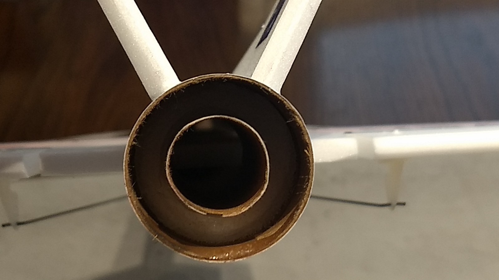
- Motor mount installed recessed till it butts against the stab tabs
-
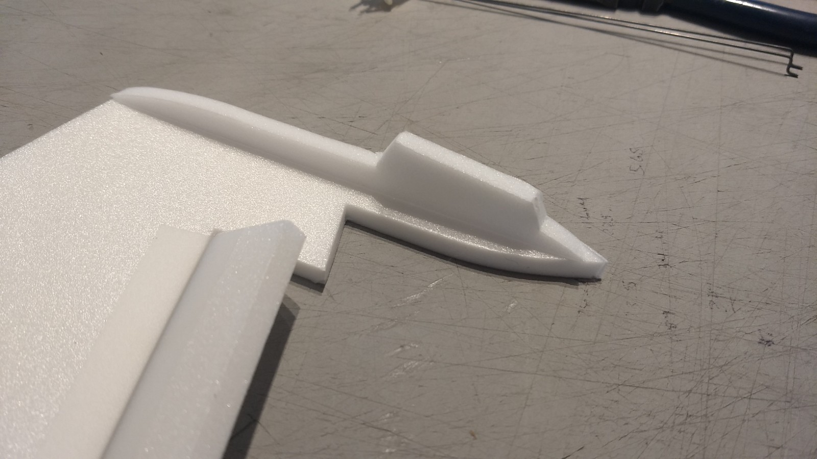
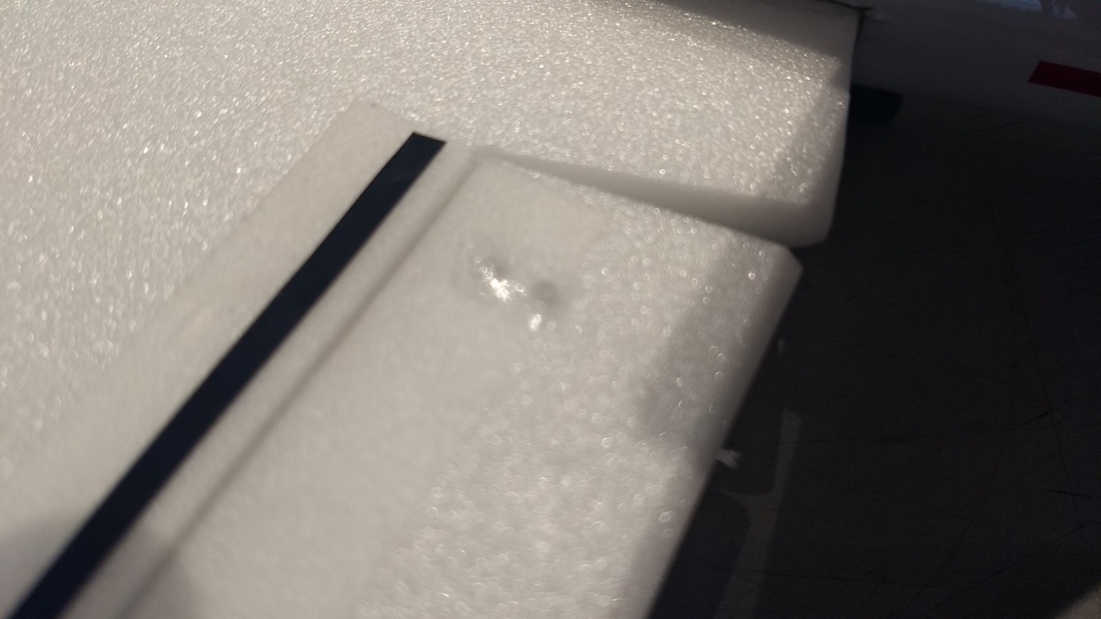
- glue wing tip pods onto each wing tip top and bottom
-
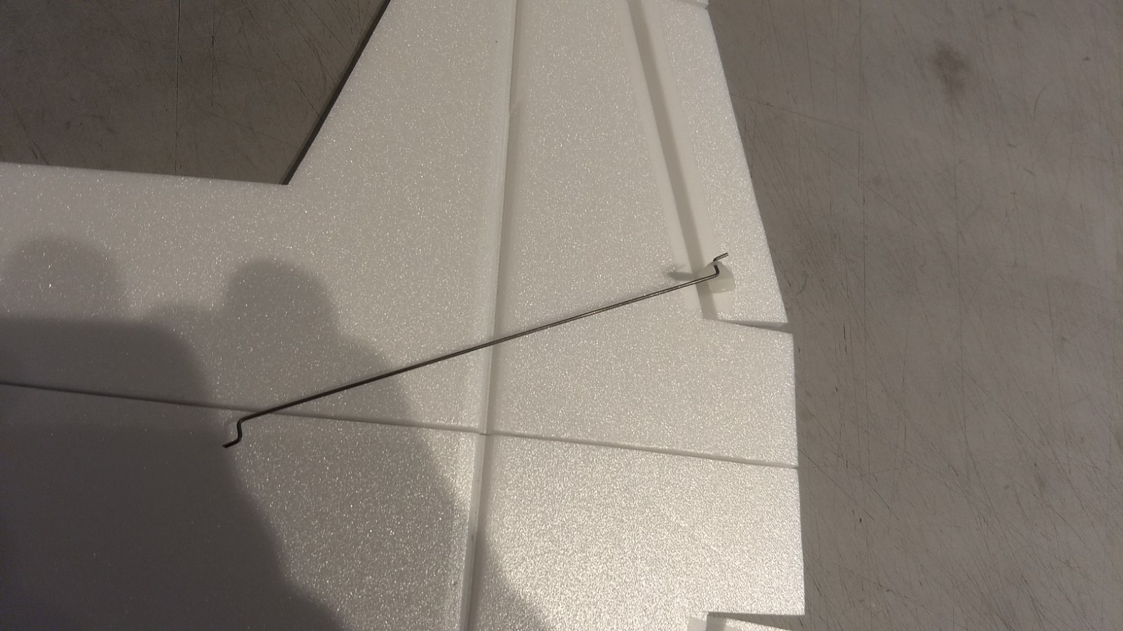
- Pushrods installed, note pushrod is closest to the model and angled inward.
-
- Add glue to top of horn prongs to lock them in place.
-
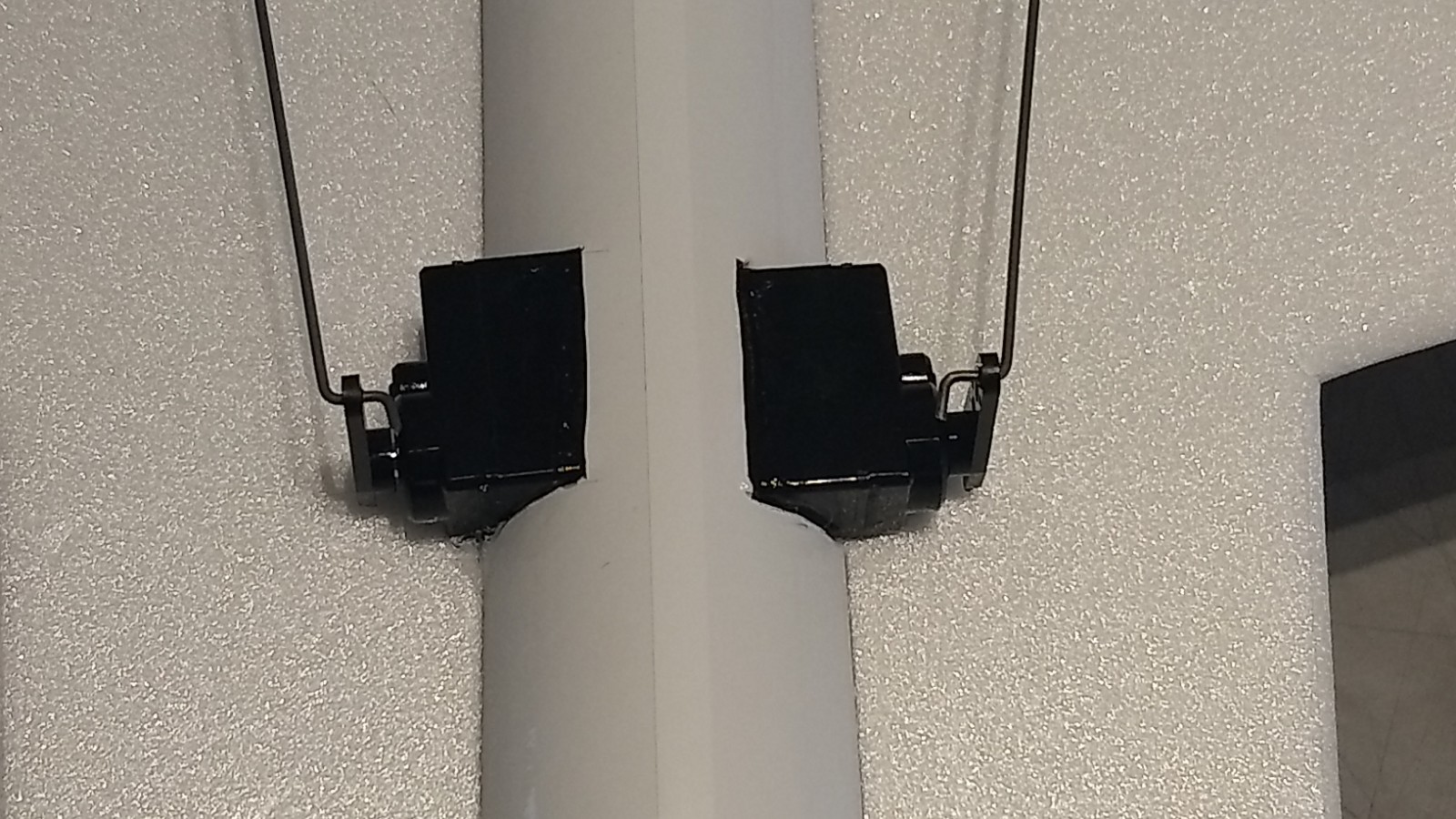
- Servo pockets cut and servos glued in place.
-
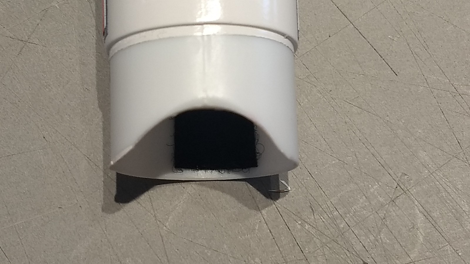
- Cut off bottom of cone shoulder and shorten to 3/4″ long
-
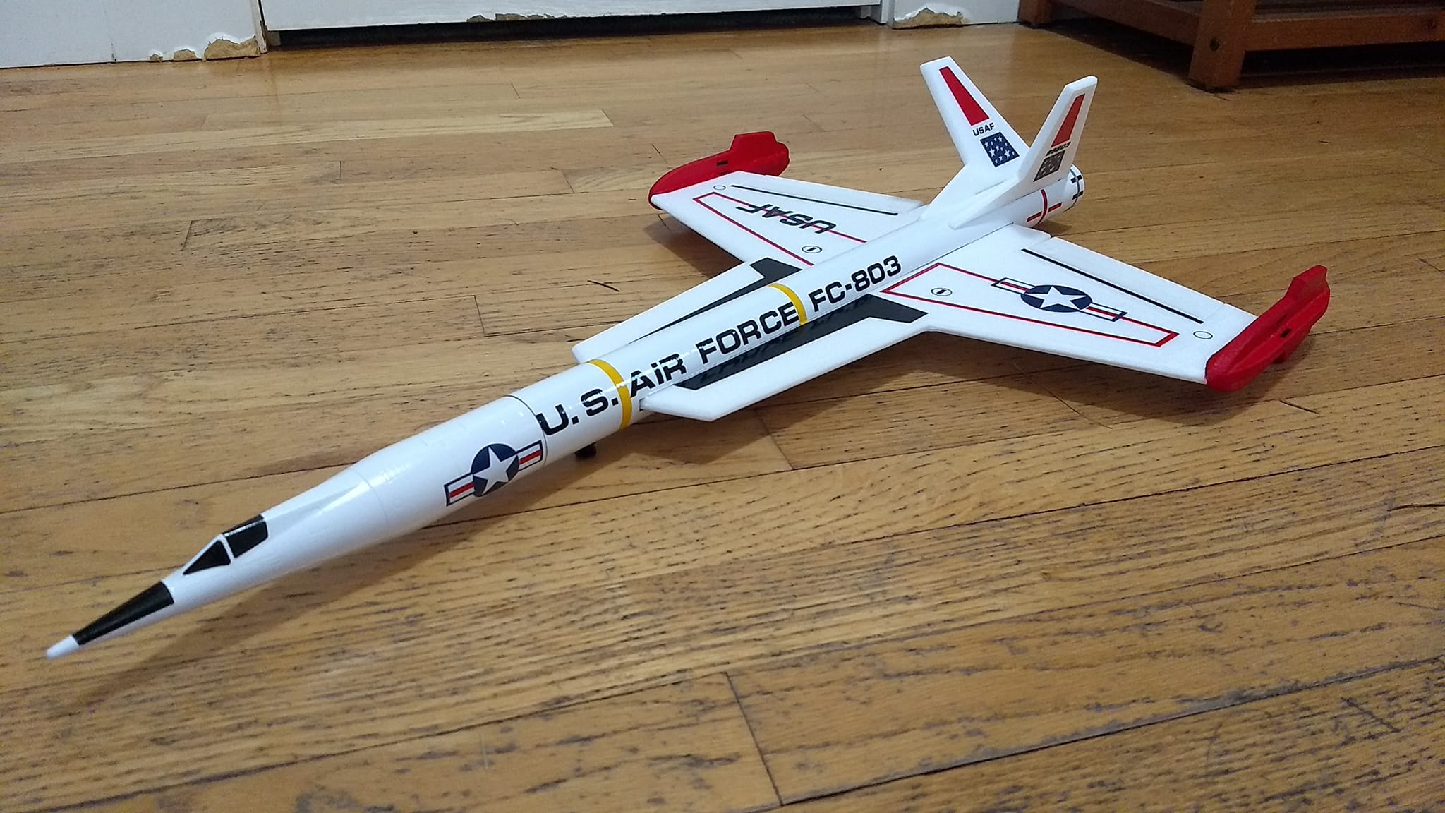
- Completed model shown with Stickershock markings and some additional details using self adhesive trim vinyl.
-
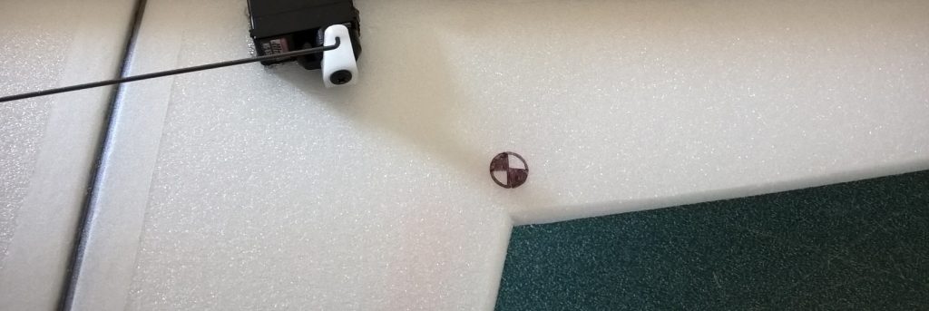
- CG location at strake/wing Leading edge intersection