
The Blue Bird Zero RC Rocket glider kit is styled after the classic Estes Rocket kit that was a hypothetical German Sounding Rocket design with German theme and english markings, if that makes sense:) It comes with a plastic nose cone, 2.6″ white tubing for the body, and 6mm depron wing, canard and tail surfaces. The body tube has the rail button holes pre-punched and wing, canard and vertical stabilizer slots pre-cut. Elevons are pre-hinged and spars are pre-installed/fit Construction and radio install is very simple. 28.5″ wingspan, 36″ length, 2.6″ diameter, 10.25 oz ready to fly. For 24mm Reloadable and single use E-6 composite rocket motors only.
High quality cut vinyl decals are available from stickershock23.com here:Blue Bird Zero Decals
Please refer to the General information for all kits tab above, then read these instructions completely before starting assembly.
CG location for rocket flight: 9 1/8″ forward from the trailing edge of the wing at the root/body tube, or about 14″ forward of the rear end of the body tube with loaded motor and battery installed as ready to fly. Depending on the hand cut slots if there is a difference in the location, go with the more forward location for the first flight.
Identify all pieces, the kit should contain:
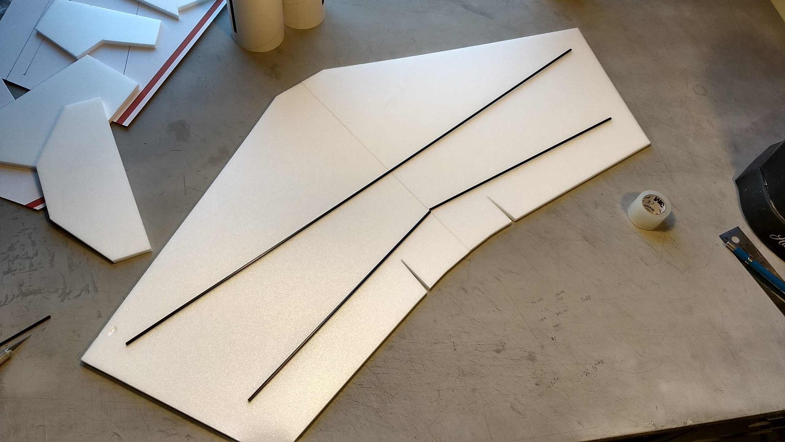
1 wing taped together
1 Canard
1 Nose Cone
2 pushrods/horns
1 coupler
1 vertical stabilizer
1 long slotted body tube(rear)
1 short slotted body tube(front)
2 pushrods/control horns
24mm Motor mount
3 6mm motor centering strips 2.75×13/16″
1 25.5″ 3mm spar or two 12.75″ 3mm spars with joiner tube
Blenderm tape.
Velcro(for battery and rx/bec attachment)
2 Rail buttons with t nuts/screws
Thrust ring
Lead weight
Spare foam (for testing paint, glue, and sanding the edges to see how it behaves)
Notes before starting:
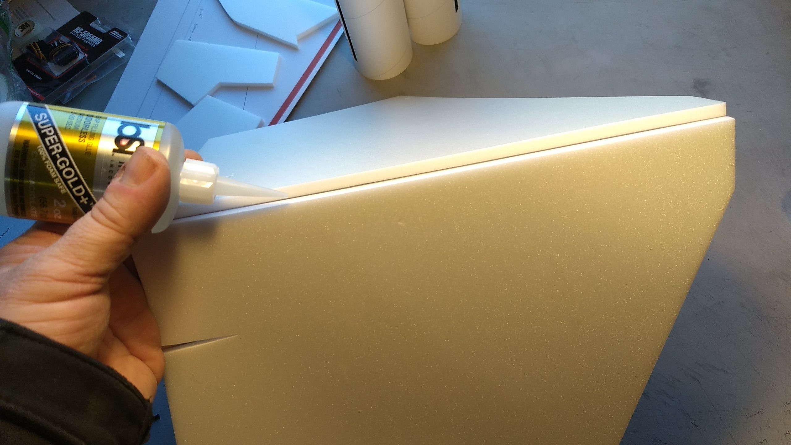
Foam safe CA+(Bob smith super gold + is good) is the only glue recommended for construction. You will also need foam safe accellerator to set the glue.
Assembly:
- Glue the taped wing joint and lay flat to set.
- If your kit came with two 12.75″ spars and a joiner tube glued to one of them, glue the other spar into the joiner tube using 5 minute epoxy or the foam safe CA+ and make sure it cures straight. This will make a single 25.5″ spar.
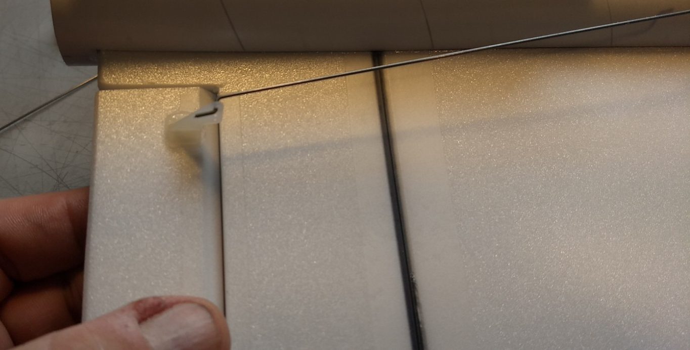
- Test fit then glue the main spar into the wing, then tape over with blenderm tape.
- Bevel cut the leading, trailing and tip edges of the wing, canard and stabilizer with a straight edge and exacto knife, just a small 1/16″ to 1/8″ is fine. Do not bevel the front of the wing and canard where it will be inside the body tube slot as it will leave a gap.
- Glue the three motor mount strips on three of the pre-marked lines on the motor mount.
- Install the front and rear rail buttons at this time in the rear tube in the pre-punched holes. The t-nut goes on the inside, then add a washer, collar and washer and secure with a screw. For the rear button you can set the T-nut on a dinner knife or stiff ruler and slide it into the body tube and press it up against the hole till it pops through, then support it with the knife/ruler while you screw the rail button in place, then you can just pull on the rail button while you snug the screw all the way down.
- Glue the front and rear body tubes together using the coupler, note there is an arrow mark on both tubes, make sure this is aligned so that the wing and canard slots are aligned. The coupler will glue about 1″ into both tubes.
- The coupler will interfere with the wing and canard slots, so cut out the coupler from the wing and canard slots on both sides using an exacto knife, make several light passes and take your time.
- Test fit the wing and canard into the slots. If needed trim or sand the slot so that they will fit. Take your time with the wing, it is a tight fit and you may need to rotate it slightly when it gets near the middle to get it to fit. I found if I can put it in and get it as far as the aileron notch, I can push back slightly and get the front in to rotate. If necessary trim/sand the front of the wing so that it will insert correctly.
- The rail buttons will be pointing down and the spars on both wing and canard will be facing down as well.
- Make sure the wing is centered left and right and tack glue in place, do the same with the canard. You may need to squeeze the body tube slightly as you glue so help it from flattening out from the slot cut. Apply a light fillet on both sides and the top and bottom of the wing/canard body tube joints.
- Test fit then glue in the vertical stab, apply a fillet on the inside and outside of the tube and make sure it is set.
- If you do not use a reloadable motor you can glue the included thrust ring into the front of the motor tube. You will friction fit the motor for flight with a small bit of masking tape to make sure it doesn’t fall out, the reloadable motor will stop on the rear closure and you don’t need the thrust ring in that case.
- Test fit the motor mount into the rear of the model. The three tabs help to center the tube and the vertical stab slot will be the final piece. Sand a little at a time on the motor mount tabs till it will just slide in place under the vertical stab tab. It should inset about 5/8″ or so. Make sure the vertical stab stays perpendicular to the wing and run a bead of CA down each side of the motor mount tabs/body tube joint and the vertical stab/motor mount joint and make sure this is set. You don’t need a ton of glue just enough to keep it in place.
- Apply CA+ to each of the control horns and press them in place in the bottom of each control surface into the pre-made holes. Note the pushrods will be on the inside of the control horn toward the center and will angle inward toward the body tube, there is a left and right.
- Apply glue to the prongs on the bottom of the wing to lock the horns in place.
The basic construction is now complete.
Radio Installation
Note: Your radio needs to be configured for Delta mixing, this means that the servo arms will move the same direction during elevator stick movement and opposite for aileron stick movement. Connect your servos to the receiver one in the aileron connection and one on the elevator connection and apply power. Use a servo arm at least 9/16” long and with holes small enough that there won’t be slop with the pushrod wire when installed. I use the hole furthest out on the servo arm, to maximize movement. On some servos there are a long two-ended servo arm, you can trim off one end if needed to get sufficient length. Zero out any trim settings on the transmitter. The model once the motor has burned out is nose heavy and flying wings lose pitch authority when nose heavy so you want as much up elevator travel for trim/flare as possible.
- Connect a servo to each pushrod. If the pushrod is too tight, you can use twist an X-Acto knife in the servo arm hole to make it larger, but be careful and do not make it too large. Once connected, tape each servo in place so that the control surfaces are centered. Look at the model from the rear. Moving the transmitter stick back(up elevator) should move both elevons up. Moving the transmitter stick to the right should move the right elevon up and the left elevon down. If you can’t get the servo reversing to give you the right polarity try swapping aileron/elevator inputs to the receiver or turning the servos over and swapping the servo arms to the other side of the output shaft. If that is correct, continue.
- The servos are attached by directly gluing the servo to the wing with foam safe CA+. Double back servo tape can loosen over time and with exposure to heat, I prefer to glue the servo in place.
- Mark where the servo will be when the control surface is neutral and cut a notch into the body tube so that the servo is inset slightly. Repeat on the other side. Attach a servo extension to each servo so that the wire will reach about an inch or more past the front of the body tube, then route the wire into the notches on each side and out the front and re-connect the servo to the receiver.
- With the radio still on, put a moderate amount of glue on the servo, being careful not to get any near the output shaft, and set it in place on the wing in the pocket you just cut, keeping the control surface centered. Do the same to the other side. Make sure the glue is set before continuing. If you need to adjust the pushrod by bending the angle at the control arm so the servo is not angled, simply do so with a needle nose pliers before gluing the servo in place.
- Make sure the control surfaces are centered, use trims if needed. Now measure the control surface movement. Full elevator movement should be 5/8” in each direction, aileron movement should be 3/8″ to 1/2″ in each direction. Since the model will be nose heavy, extra elevon movement helps to give sufficient authority during glide.
- If you have a flap/elevator mix you can program up elevator to a switch setting. The model needs approximately 1/4″ of up trim for glide. If you can’t set the up elevator trim to a switch on your radio you’ll have to manually put in boost and glide trim which is hard to do while flying the model. You can also use flight modes to set different launch and glide elevator trim settings and control those via a switch.
- I can only recommend testors/model master enamel spray or Krylon Short Cuts small enamel spray cans at this time, others I’ve tried damage the foam surface. I left the rear of the body tube and wing/tail unpainted to save weight. Balance the model after painting as it adds weight. The blue portion of the nose section starts about 2″ ahead of the front of the canard.
- I applied a strip of 2″ clear packing tape to the bottom of the rear of the body tube to keep it from getting wet/dirty on landing or from soot on the rail.
- Install your receiver inside the front top of the body tape using the included velcro as far back as you can place it and still have the battery wire reach to the front of the body tube for attachment.
- Install your battery in the bottom front of the body tube and tape in place for now.
- Insert your heaviest loaded rocket motor into the motor mount
- Support the model at the balance point indicated for boost. I use two pencils with the eraser pointed up and held in place with a small hand vice. Place the model upside down on the pencil erasers on the balance point indicated above.
- Adjust the battery placement and see if you can get it to balance without adding weight. You can shift it forward into the nose or back into the body tube as required. You can also remove the receiver case which saves a few grams if you are just slightly nose heavy. Use velcro to permanently mount the battery in place. If necessary use some of the included lead weight as far forward into the tip of the nose to balance it, or in the tail as needed. Glue the lead weight in place so it does not shift during flight. Do not try to fly the model too nose or tail heavy. Remember, a nose heavy model flies poorly, a tail heavy model flies once. My model did not need any nose weight for correct balance.
Flying: See the General Instruction link at the top for flying instructions. Be ready on the first few flights to keep the model straight till you have the trims set perfectly for boost and glide.
-
- Glue wing joint
-
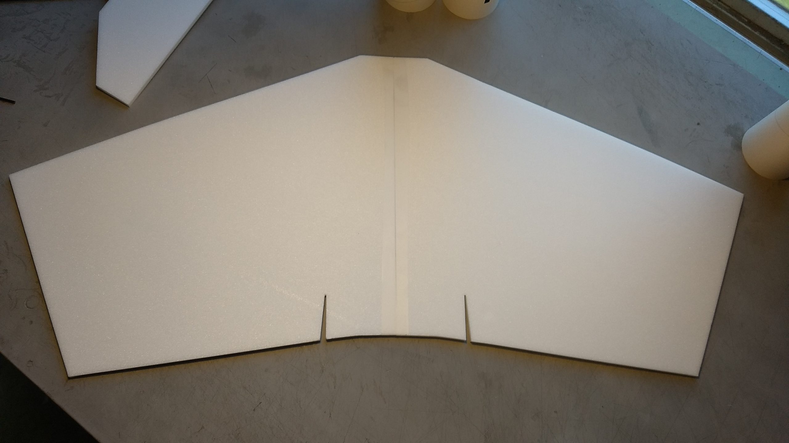
- Lay wing flat to dry
-
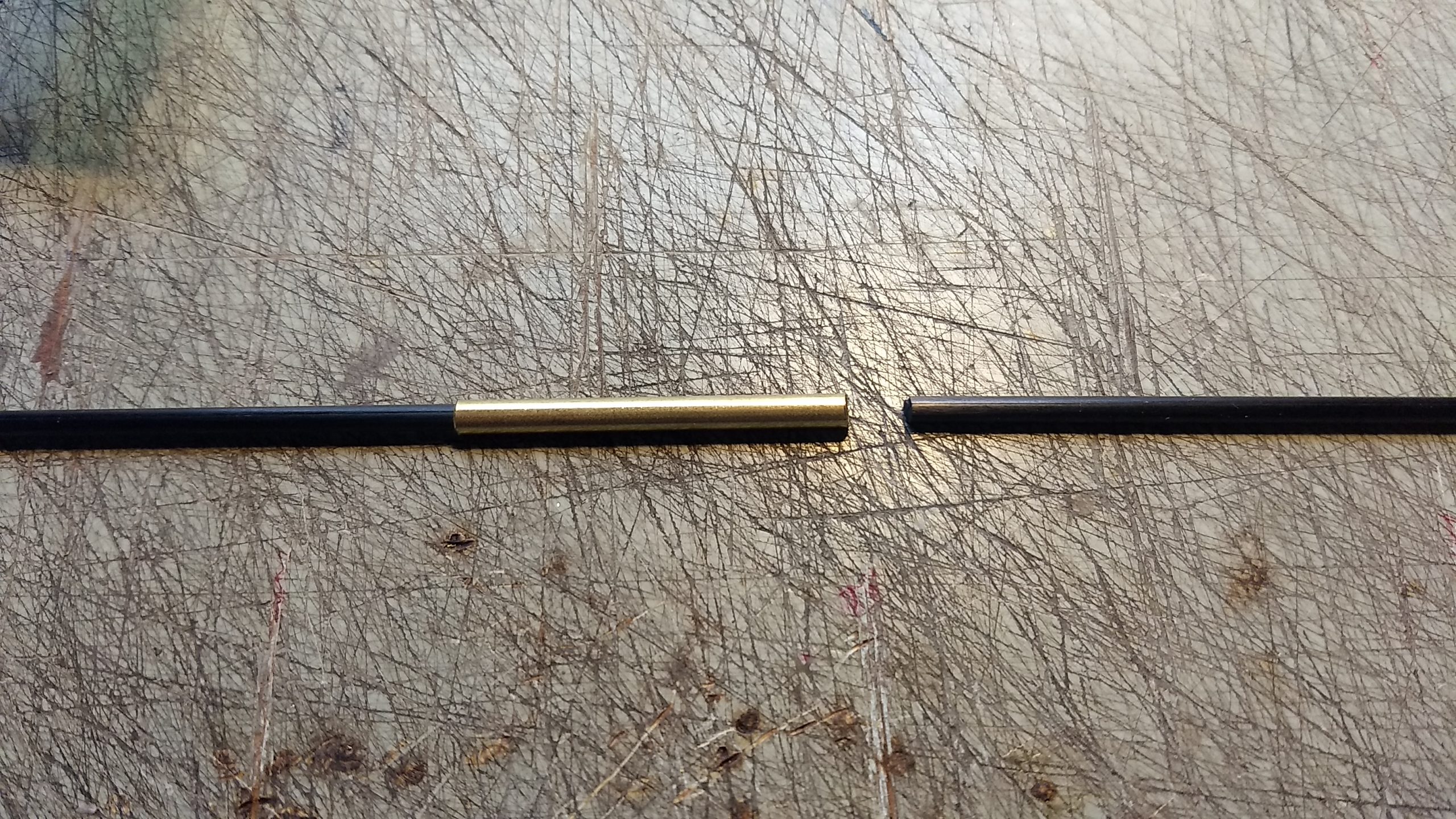
- If your kit came with short spars with a joining tube attached to one, join it with the other rod using 5 minute epoxy or foam safe CA+
-
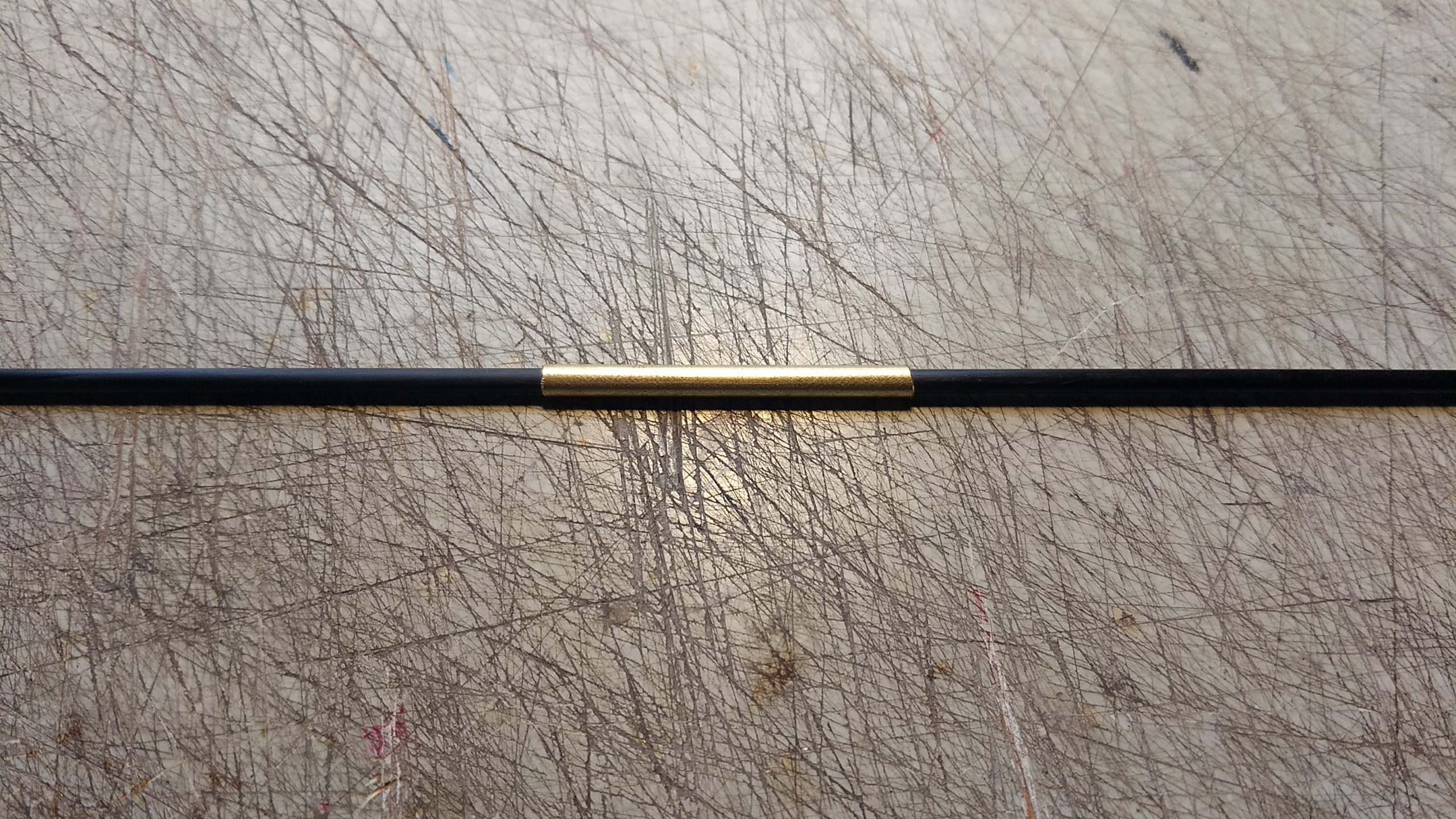
- Spar joined.
-
- glue main wing spar in bottom of wing and tape over with blenderm tape.
-
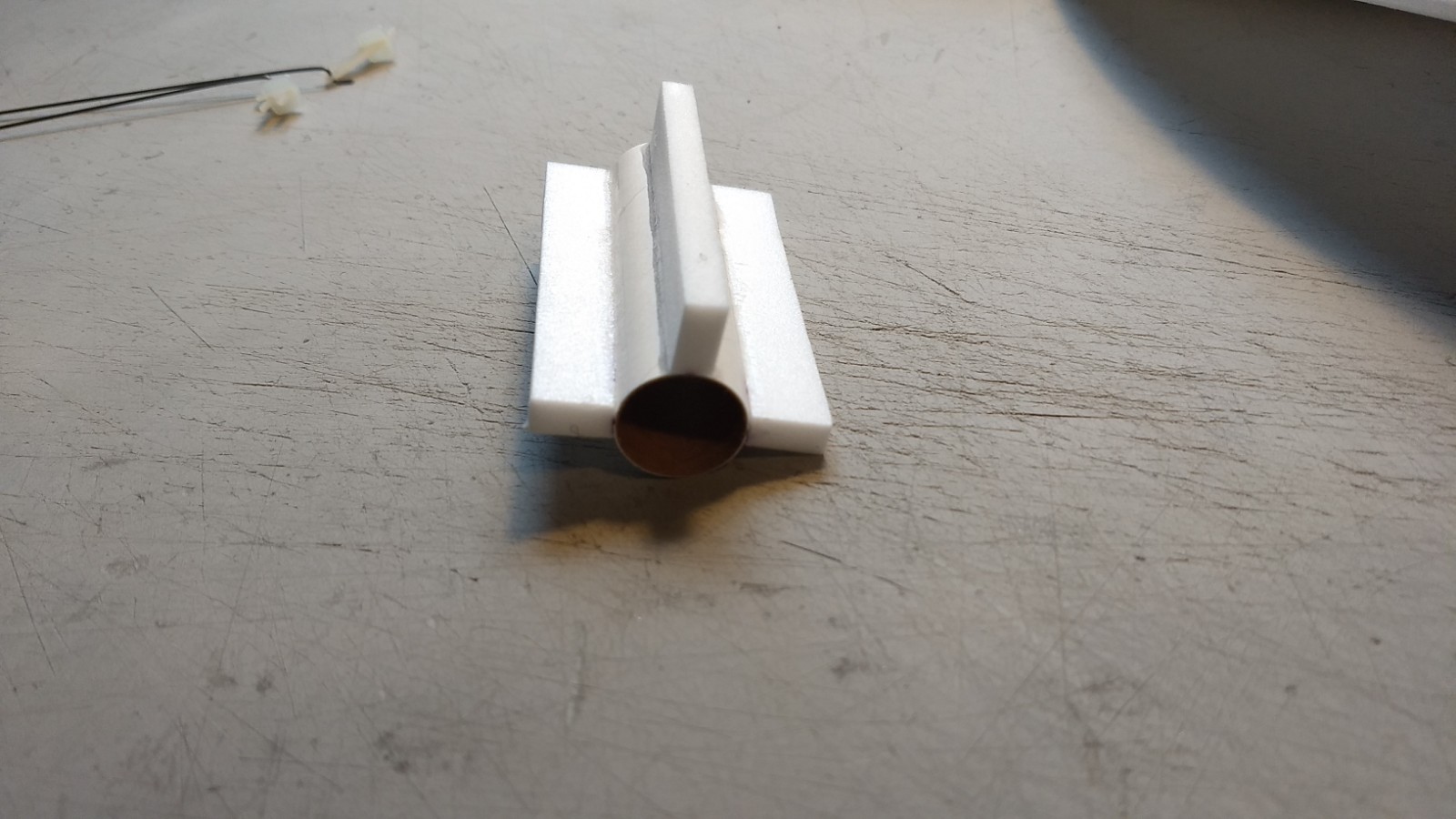
- Glue the three foam tabs onto the motor mount on the lines marked.
-
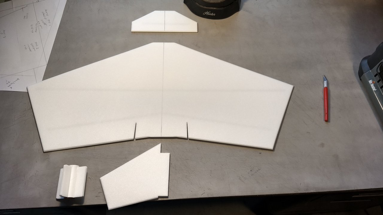
- Major sub-assemblies
-
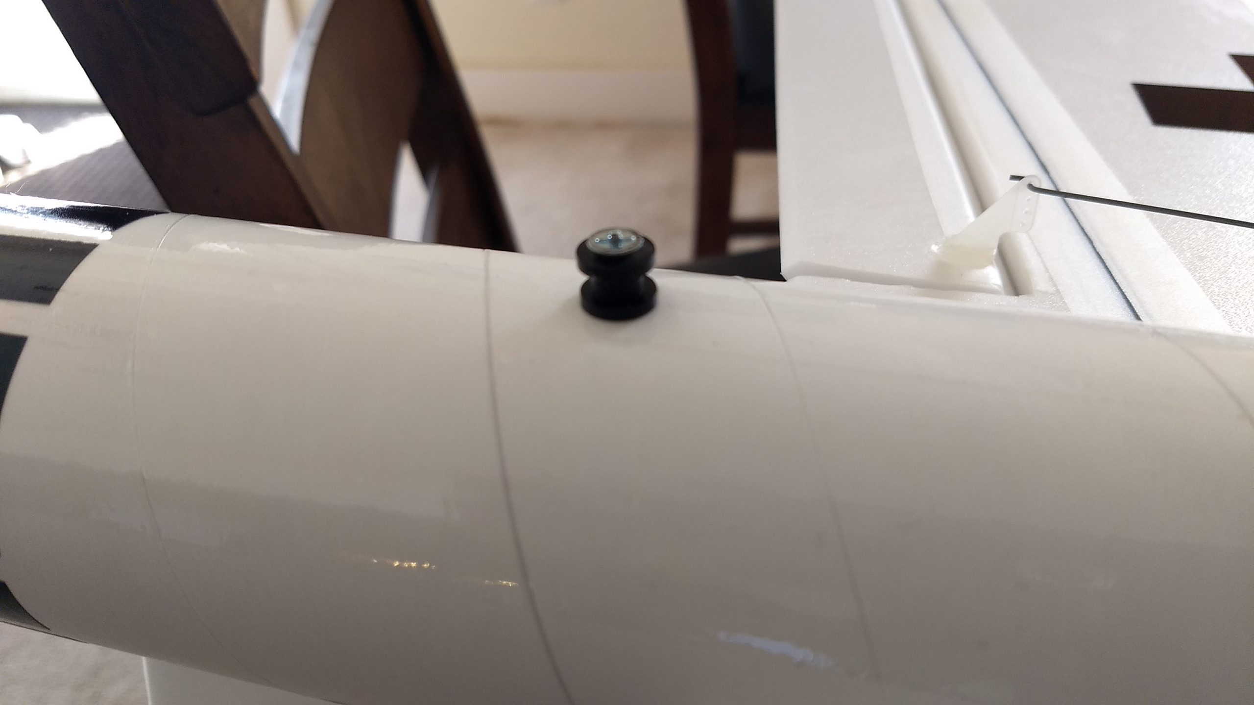
- Rail buttons installed in rear tube.
-
- Join the two tubes using the coupler keeping the alignment arrows aligned.
-
- Cut out the coupler that protrudes into the wing and canard slots
-
- Test fit then glue the canard and wing in place keeping them centered.
-
- Glue the vertical stab in place.
-
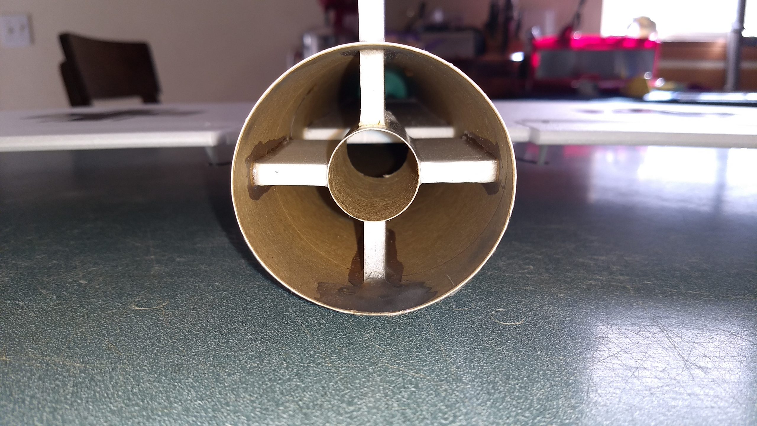
- Motor mount inset about 5/8″ and keeping vertical stab perpendicular to wing.
-
- Glue the two control horns in the bottom of each control surface in the pre-punched holes.
-
- Glue applied to the tops of the horn prongs to l\ock them in place.
-
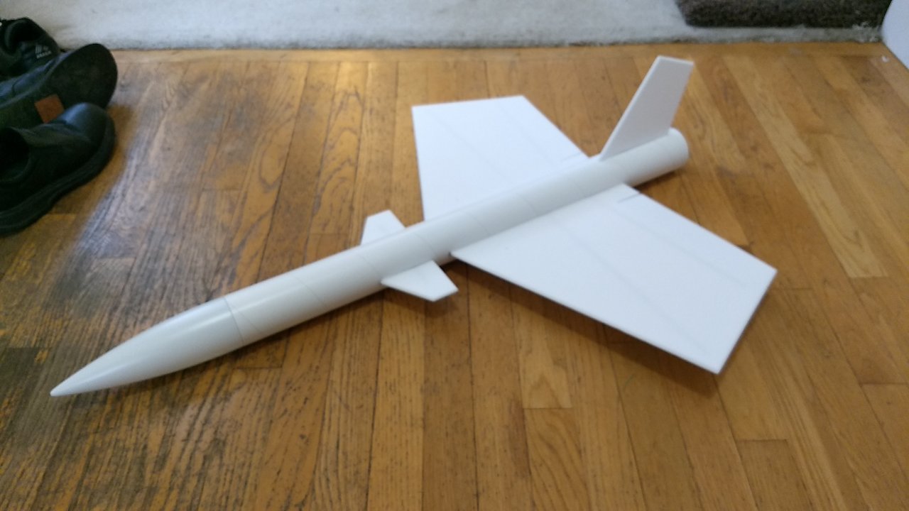
- Completed Airframe
-
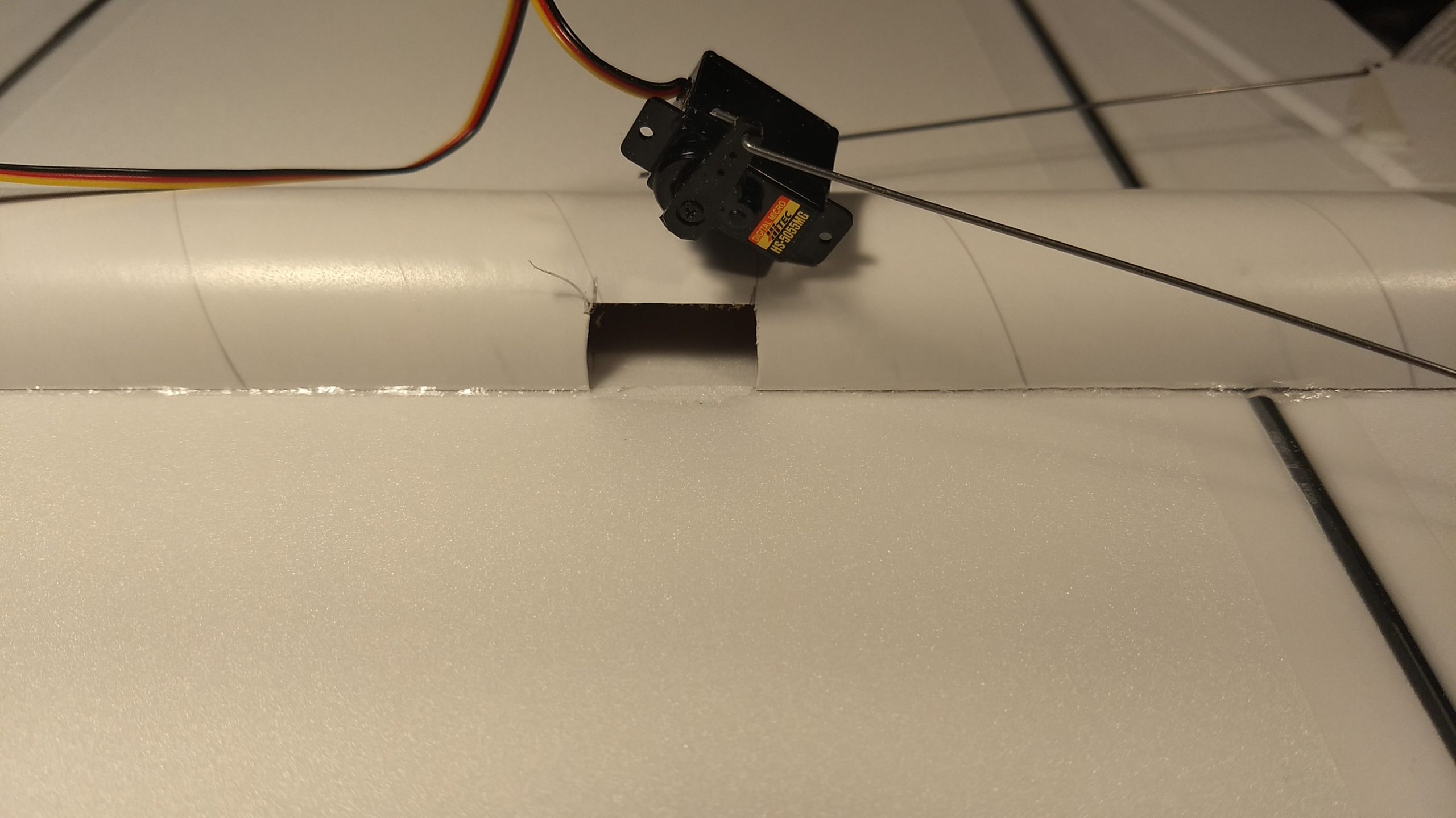
- Cut a pocket in the body tube for each servo
-
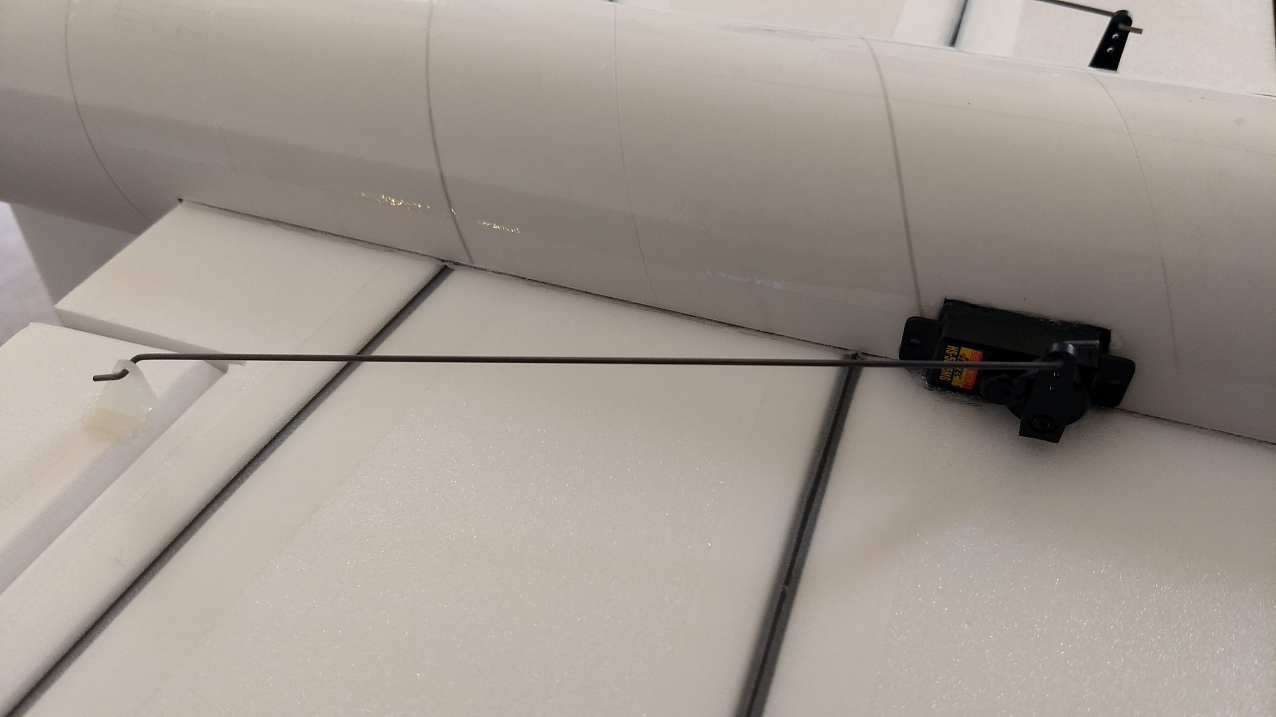
- Servo notches cut and servos inset into the body tube and glued in place.
-

- Receiver and battery connected out the front of the body tube. Power up the radio and adjust control throws and glide/boost settings.
-
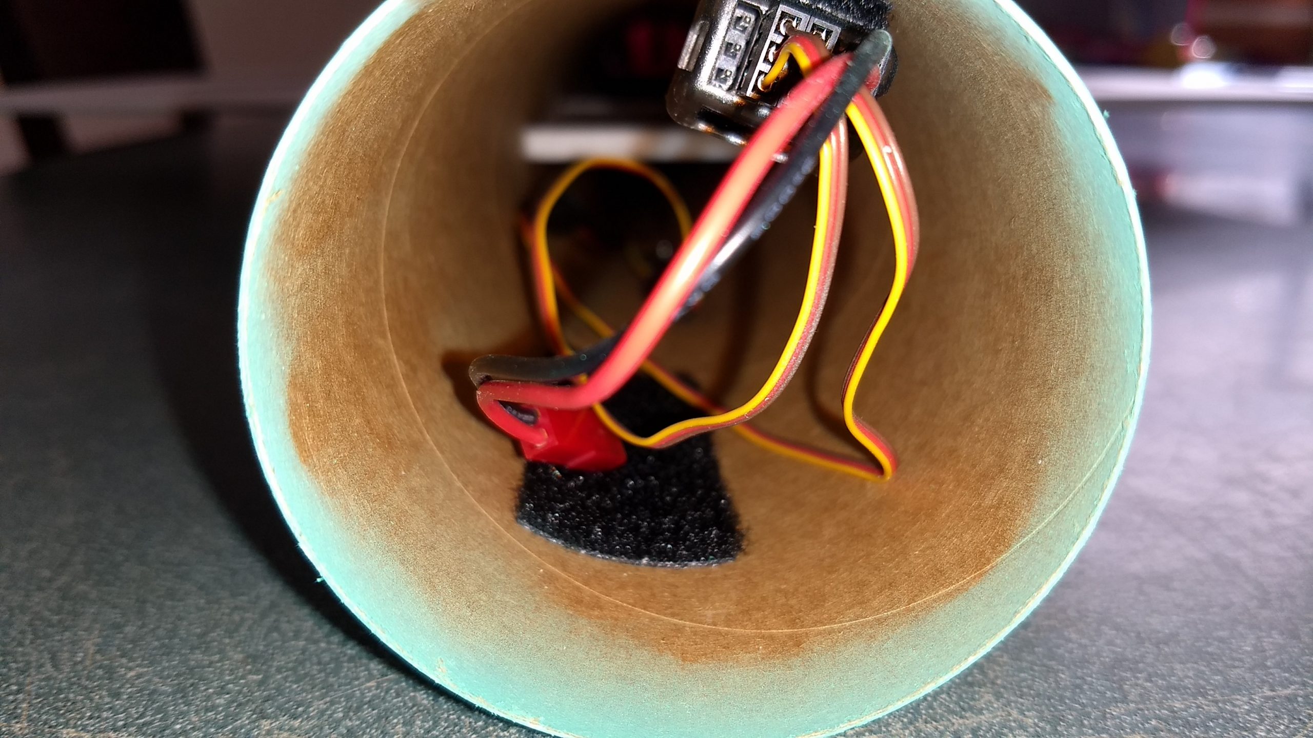
- Receiver mounted inside the body tube with velcro, battery secured with velcro in nose cone or body tube as required for balance.
-
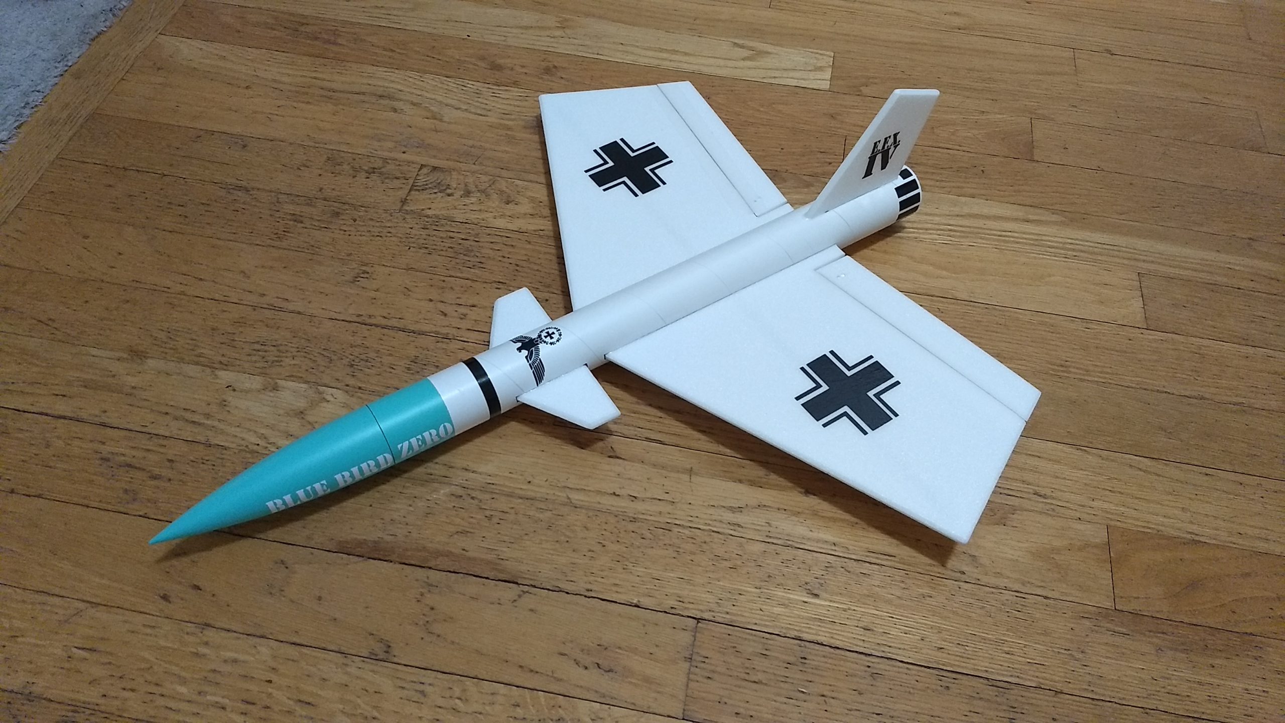
- Completed model
-
- Stickershock Decals