These instructions for experienced R/C rocket glider folks that that are L1 certified and want to build an upscale rocket glider for the 29mm H-13 Aerotech composite rocket motors. This model is designed to be ultra light weight for the size and only use the H-13 or G-12 single use 29mm Aerotech motors in this model. For G-12ST flight weight should not exceed 24-25 oz rtf, for H-13 32 oz rtf. This model with G and H motors light weight allow it to be flown under FAR101 rules without a rocketry waiver. UAS guidelines still may require approval for flight above 400′.
The model features a low mounted delta wing with dihedral It has a light wing loading giving it a very nice glide and easy/stable boost, and the dihedral helps keep it level unless you give it a turn command. Construction is very simple. You will need a transmitter with flight modes or elevator/flap trim function and elevon mixing, receiver, 2 metal or carbon gear 10 gram type servos and two 36″ servo extensions.
This model is intended to use 9mm depron foam available from rcdepron.com only. In order to save you $$ on shipping, you can purchase the foam required directly from them by sending $35 to gregtanouslasering@yahoo.com for the foam to be shipped directly to you, or to contact him if you have further questions.
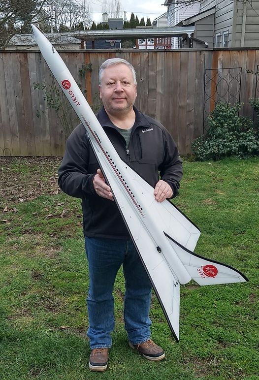
Cut vinyl decal sets that will fit this model shown are available HERE You’ll need to contact Stickershock and say you want the larger set but upscaled by 1.5x. Specs: 56″ length, 34″ wingspan, 27 oz rtf, for 29mm H-13 or G-12 single use Aerotech motors.
CG location for rocket flight: 18.75″ measured forward from the trailing edge of the wing. This should be measured with a loaded rocket motor and battery installed as you would be ready to launch the model. If using the H-13 motor Do not exceed 32 oz rtf with motor, that is the slowest vertical boost weight for safe flight.
Please refer to the General Information Link above then read the instructions completely before starting assembly. The assembly photos are for general reference but may not include every step in the instructions. If you want hardcopy to work from, all you have to do is click/drag/select and copy all of the text below, open word and paste with “keep original format” and it looks exactly like it does online then you can print it.
Upscale Aurora Clipper Rocket glider instructions:
Short Kit Parts:
1 bt-80 coupler
1 PNC-80K Nose Cone with the base removed
2 lightweight BT-80 Body Tubes marked for the wing and tail and with the rail button holes punched.
2 long 3mm solid carbon main spars
2 medium 3mm solid carbon spars for the angled secondary wing spars
1 short 3mm solid carbon spar for the tail
2 rolls of 1″ wide 3m blenderm tape
Self adhesive Velcro(for battery and rx/bec attachment)
2 Rail buttons with t nuts/screws
3 oz Lead weight or bb’s for nose weight.
Adapter wire to adapt a small 1s 500mah lipo battery or similar to the receiver for power.
2 control pushrods
2 adjustable control horns
4 basswood strips to glue to the motor tabs to prevent heat damage
29mm motor mount tube.
Notes before starting:
Reference to glue, CA, or CA+ means foam safe CA+, normal CA+ will melt the foam! Normally you need to use accelerator to get the CA to set on the foam since there is nothing for it to soak into and activate.
I bevel the edges of the foam surfaces before assembly which helps reduce drag and makes the model look nicer. I simply use a sharp Xacto knife and a metal straight edge to cut a 1/16-3/32″ wide 45 degree bevel on the edges on both sides of the wing and tail, on the curved areas I do it freehand and touch up with a little 320 grit sandpaper. If you decide to sand the edges, use a block and a VERY light touch and do small areas at a time to avoid the paper catching the foam and tearing it. Do any shaping before assembly.
The depron has a green printed ink on one side, if you use a gell based high alcohol hand cleaner apply and rub with your finger and let soak, about 50% will come off, you may try a couple of applications. I put this on the bottom near the wing joint that is taped over so it isn’t very obvious.
Epoxy is not needed in this model. It is designed to be assembled ONLY with Bob Smith foam safe medium thick CA+ and accellerator or equivalent. Weight is critical and the model is designed for the thrust and flight loads. Weight in the rear end is bad and will require additional weight in the front of the model.
Assembly:
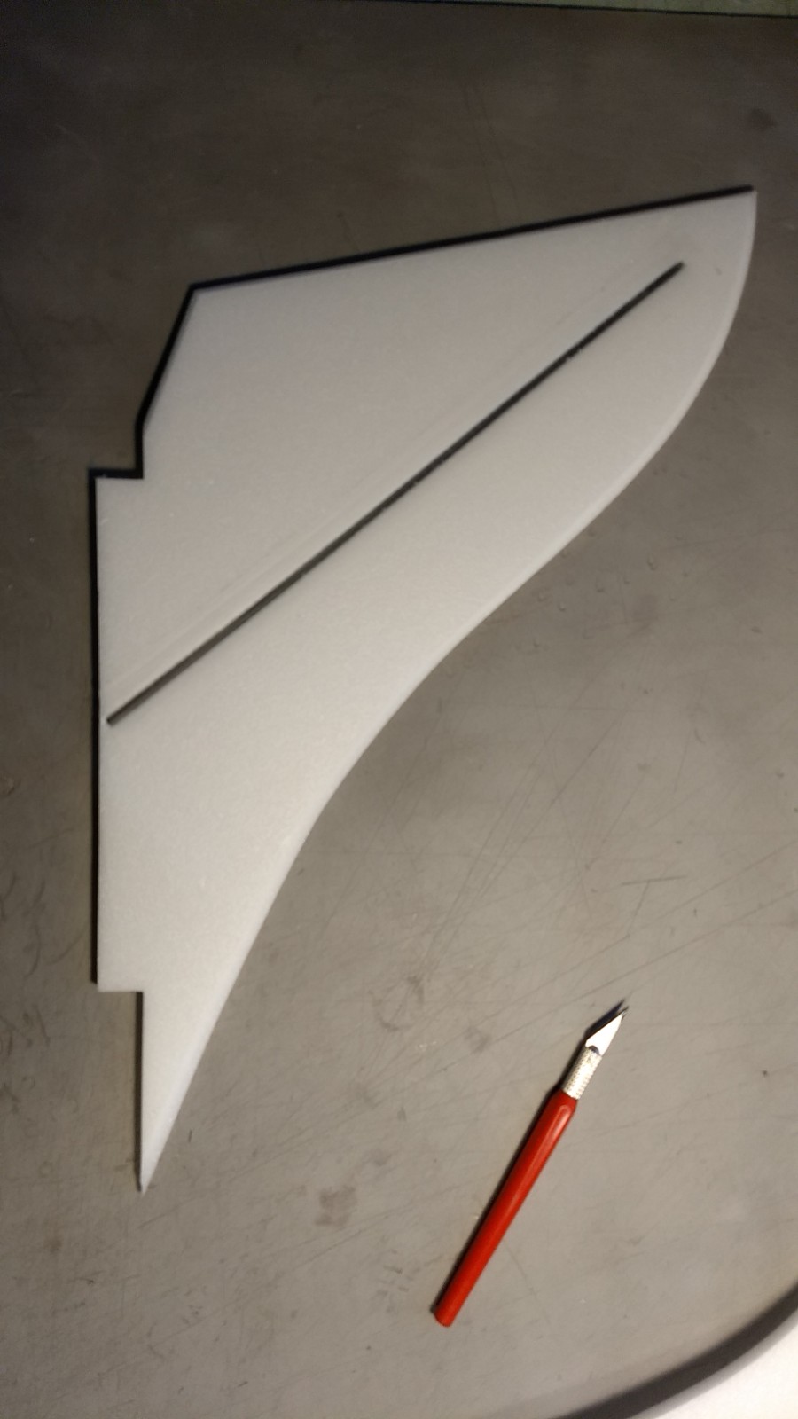
- Cut out the wing halves, wing reinforcing strips and motor mount strips using the dimensions supplied in the kit.
- Cut out each elevon from the wing. The elevons are 2.75″ wide and 10″ long. The inboard end starts 3″ from the root edge of the wing.
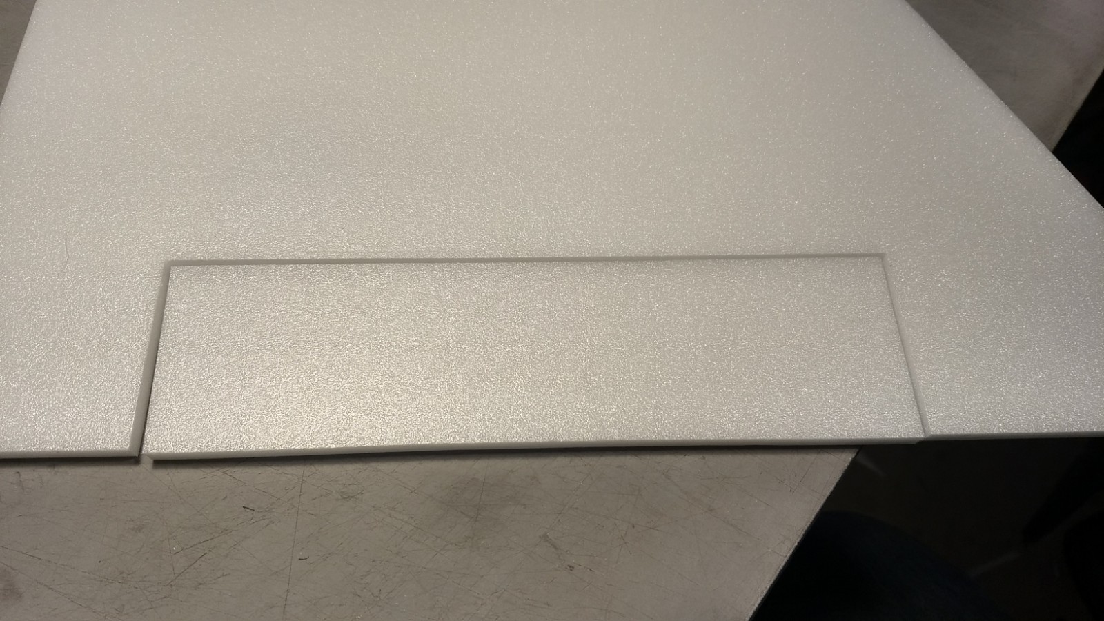
- Trim the end of each elevon 1/8″ shorter to allow clearance for the elevon to move, then flip each elevon over upside down and cut the front of each elevon at a 45 degree bevel.
- Use 3m blenderm tape to tape each elevon in place on the top of the wing, then flip the elevon over on top of the wing and use two strips of blenderm to tape the bottom of the joint overlaping the tape strips in the middle and making sure it wraps around the bottom of the elevon and the bottom of the wing, see photos.
- Bevel cut the root edge of each wing half so that when joined together the wing will make a shallow dihedral angle. I usually lay the wing on top of the body tube upside down and let the wing tips touch the top of the table to set the proper dihedral angle. Tape the bottom of the root edge of the wing halves together with 3 overlapping lengths of blenderm tape or sturdy 2″ wide packing tape or both.
- Bevel or sand the edges of your wing.
- V groove using an exacto knife and straight edge the bottom of each wing half for the main and angle spars. Drag the end of the spars in the groove several times so that the spars will inset flush with the foam. The main spars are located 3.5″ forward of the trailing edge of the wing. The secondary spars are located 12″ ahead of the main spars at the root edge of the wing and angle backwards slightly so that they end about 1/2″ from the edge of the wing. See photos.
- Glue the spars in place using foam safe CA+ and then tape over with blenderm tape.
- Dry fit the body tubes together using the coupler. Mark the bottom of the tubes with a straight angle aluminum piece for the length of the wing root. Mark the top rear tube for the slot needed for the vertical stab and mark the rail button holes. I offset the rail buttons to the right of the vertical stab about 1-1.5″ and inset about 1.5″ from each end of the rear tube.
- Cut out the vertical stab using the template included
- V groove the stab for the vertical stab spar with an exacto and straight edge and drag the end of the spar several times so it will inset flush with the foam.
- Glue the stab spar in place and tape over with blenderm tape.
- Glue a basswood strip onto the root edge of the vertical stab tab.
- Sand the vertical stab edges round or bevel with an exacto.
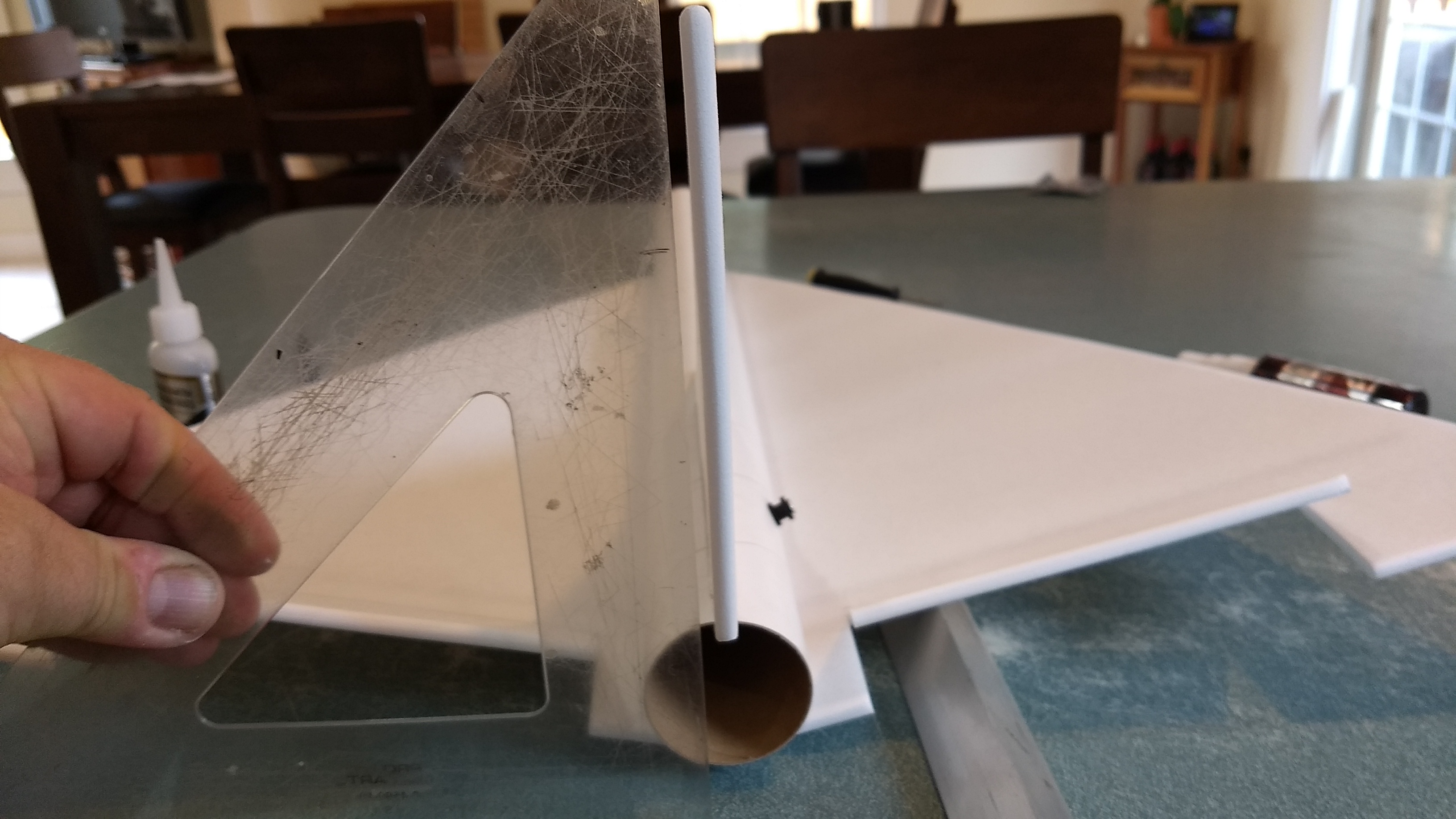
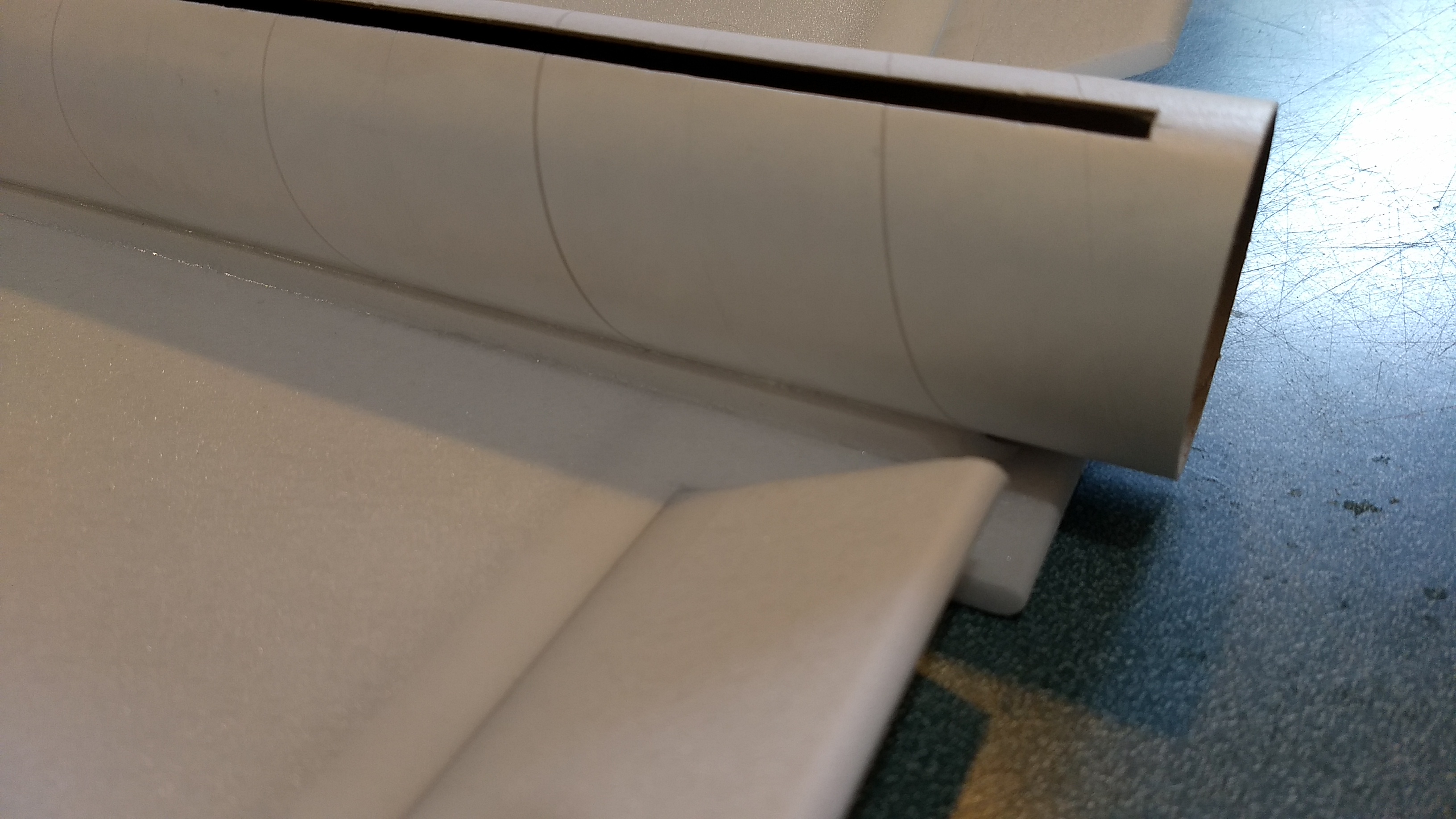
- Cut a slot for the vertical stab, starting 3/4″ from the rear end of the tube and long and wide enough to fit the stab tab.
- Cut the holes for the two rail buttons with an exacto knife, I inset them about 1.5″ from each end of the rear tube.
- Install the rail buttons.
- Glue the coupler halfway into the tube with the rail buttons, it will go into the end without the tail slot
- Glue the tube without the coupler onto the coupler in the rear tube making sure the bottom wing alignment lines are aligned on the two tubes.
- The wing will be unfolded and mounted on the bottom of the body tube.
- Lightly sand the bottom fuselage wing line and apply a squiggle of glue about 1/2 wide to the body tube wing line, the wing joint, and 1/2″ on either side of the wing joint.
- Lay the wing upside down onto the body tube making sure the rear of the wing is aligned with the rear of the body tube and the front and rear longitudinal alignment line is in line with the center taped wing joint. You want to be sure the wing makes full contact with the body tube and is set before you continue. Depending on how the wing joint was cut, the wing tips may or may not touch the table top when gluing the wing in place. The amount of dihedral is not critical, more dihedral will be more stable in roll axis in glide but will have slightly reduced glide times.
- Once the glue has set flip the model over and apply some glue into the wing/body tube joint to make sure is is secure, I squeeze some glue about every inch along the joint on both sides and make sure it is set before continuing.
- Apply some glue to the long foam angle strips on the wide flat surface. Insert this into the wing/fuse joint to add extra gluing surface. DO NOT PUSH IT IN too hard, it will cause the body tube to rotate, you just want it to go into the joint. Repeat on the other side, then apply a fillet of glue to the foam where it hits the body tube and the wing to add extra gluing surface.
- Test fit the vertical tail into the slot and make sure it fits. Make sure the tail is straight with no warps, bend carefully by hand to straighten it if needed. Glue into the slot using foam safe CA+ making sure the tail is perpendicular to the wing and is straight. When gluing in the motor mount you can adjust the vertical stab position.
- Glue the basswood strips onto each foam motor mount tab.
- Mark your motor mount tube with four evenly marked spots and draw lines the length of the motor tube.
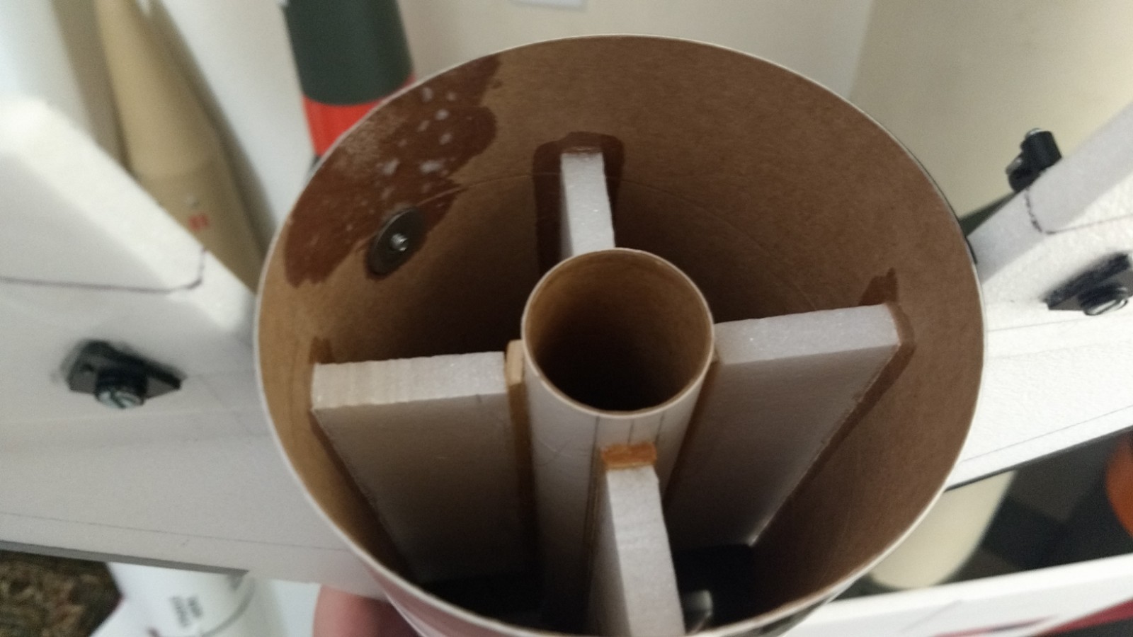
- Glue the foam centering strips on the motor mount tube. The ply will glue to the motor tube and protect against motor heat damage. You will glue two strips on either side of the motor tube and one on the bottom. Use your eye and make sure they are approx as shown in the picture.
- There is no need for a retainer ring it will just add weight and there is no ejection charge that would require retention, just use a small bit of masking tape to keep the motor from falling out, the motors have a thrust ring built in.
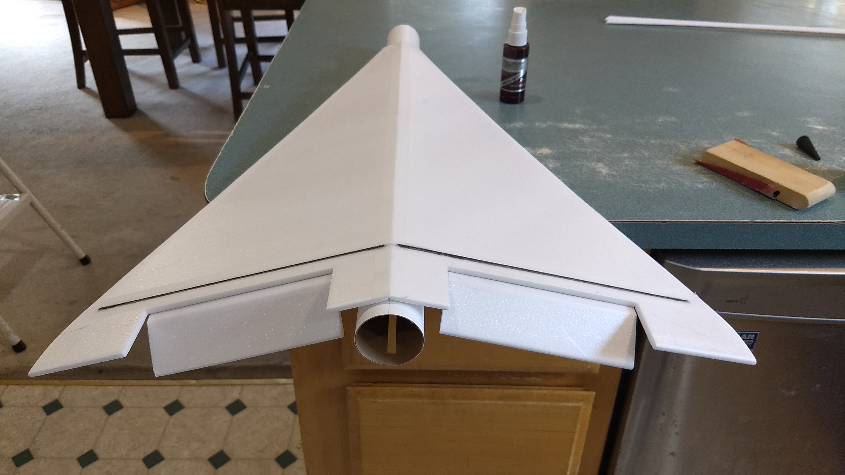
- Test fit the motor mount, If you need to sand the tabs glued on the motor tube so that it fits under the vertical fin tab, and into the body tube. Do so carefully till it will insert fully and is recessed about 3/4″ from the rear of the body tube. Glue the motor mount into the rear of the model. Make sure you glue the tube so that the motor block is forward if installed.
- Mark and punch a hole for the adjustable control horn about 3/4″ from the inboard end of the surface and install the control horns so that they are sticking up on the top of the wing. Apply some CA to the plastic reinforcing plates on the top and bottom of each horn to reinforce those areas. I trimmed the threaded rod so that about 3/4″ sticks up above the control surface and you can adjust for the throws you need.
The basic construction is now complete.
Radio Installation
Note: Your radio needs to be configured for Delta mixing, this means that the servo arms will move the same direction during elevator stick movement and opposite for aileron stick movement. Connect your servos to the receiver one in the aileron connection and one on the elevator connection and apply power. Use a servo arm at least 9/16” long and with holes small enough that there won’t be slop with the pushrod wire when installed. I use the hole furthest out on the servo arm, to maximize movement. On some servos there are a long two-ended servo arm, you can trim off one end if needed to get sufficient length. Zero out any trim settings on the transmitter. The model once the motor has burned out is nose heavy and flying wings lose pitch authority when nose heavy so you want as much up elevator travel for trim/flare as possible.
- Connect a servo to each pushrod. If the pushrod is too tight, you can use twist an exacto knife in the servo arm hole to make it larger, but be careful and do not make it too large. Once connected, tape each servo in place so that the control surfaces are centered. Moving the transmitter stick back(up elevator) should move both elevons up. Moving the transmitter stick to the right should move the right elevon up and the left elevon down. If you can’t get the servo reversing to give you the right polarity try swapping aileron/elevator inputs to the receiver or turning the servos over and swapping the servo arms to the other side of the output shaft. If that is correct, continue.
- Mark the body tube where each servo will be inset and cut a pocket to recess the servo till it hits the mounting tabs.
- Attach a 36″ servo extension to each servo(long enough to reach the front of the body tube) and route the servo wire to the front of the model and reconnect to the receiver.
- Keeping the radio powered up make sure the elevons remain centered and glue each servo against the wing and into the pocket in the body tube.
- Make sure the control surfaces are centered, use trims if needed. Now measure the control surface movement. Full elevator movement should be 1.5” in each direction, aileron movement should be 3/4″ in either direction. Since the model will be nose heavy, extra elevon movement helps to give sufficient authority during glide.
- If you have a flap/elevator mix you can program up elevator to a switch setting. The model needs approximately 1/2” of up elevon during glide. Alternatively if you have flight modes you can set up flight modes so that trim is unique to each mode, that way you can pre-set boost and glide trim for each mode using the xmitter trim tabs. If you can’t set the up elevator trim to a switch on your radio you’ll have to manually put in boost and glide trim which is hard to do while flying the model.
- Use the included Velcro to attach the receiver inside the shoulder of the nose cone. This allows you to be able to remove and replace the receiver if needed for repairs or for removing the servo wires.
- Attach the battery either inside the nose cone shoulder as far forward as practical using the remaining velcro. You may wish to wait till balancing the model to mount the battery to place it in the proper position to avoid having to add nose weight if possible.
- Use a black sharpie to add panel lines if desired
- I did not paint the model to save weight especially at this size. I did add some clear packing tape to the bottom of the front of the body tube to help keep it from getting dirty/wet on landing.
- I used some spare trim vinyl to add the accents on the leading edges of the wing and tail and used a hot hair dryer to soften them and push them down into the foam for a secure set. If you use the decals from stickershock you can do the same thing after they are applied to set them.
- Re-install the receiver and battery
- Insert your heaviest loaded rocket motor into the motor mount
- Support the model upside down at the balance point indicated for boost. Glue lead weight in the nose as needed to balance it. Do not try to fly the model with it balancing it behind this point. The adage is, a nose heavy model flies poorly, a tail heavy model flies once.
- If you want to fly on the G-12 motors you can get an extra nose cone and balance it for the lighter motor and use a heavier motor for the H-13, or you can make your nose weight removable, it’s about 3/4 ounce difference in nose weight and about 3 oz in total rtf weight.
- I have noted that the H-13’s tend to swell slightly and can become tight in some brands of 29mm tubing, i use an exacto knife to remove the label before flight and this helps prevent that, if it does get stuck, let it cool completely before trying to remove the case.
Flying: See the General Information link at the top for flying instructions. Be ready on the first few flights to keep the model straight till you have the trims set perfectly for boost and glide.
-
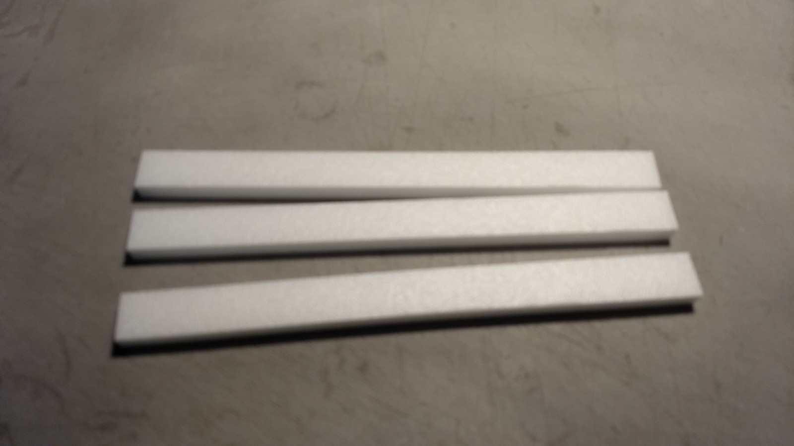
- Centering strips cut out.
-
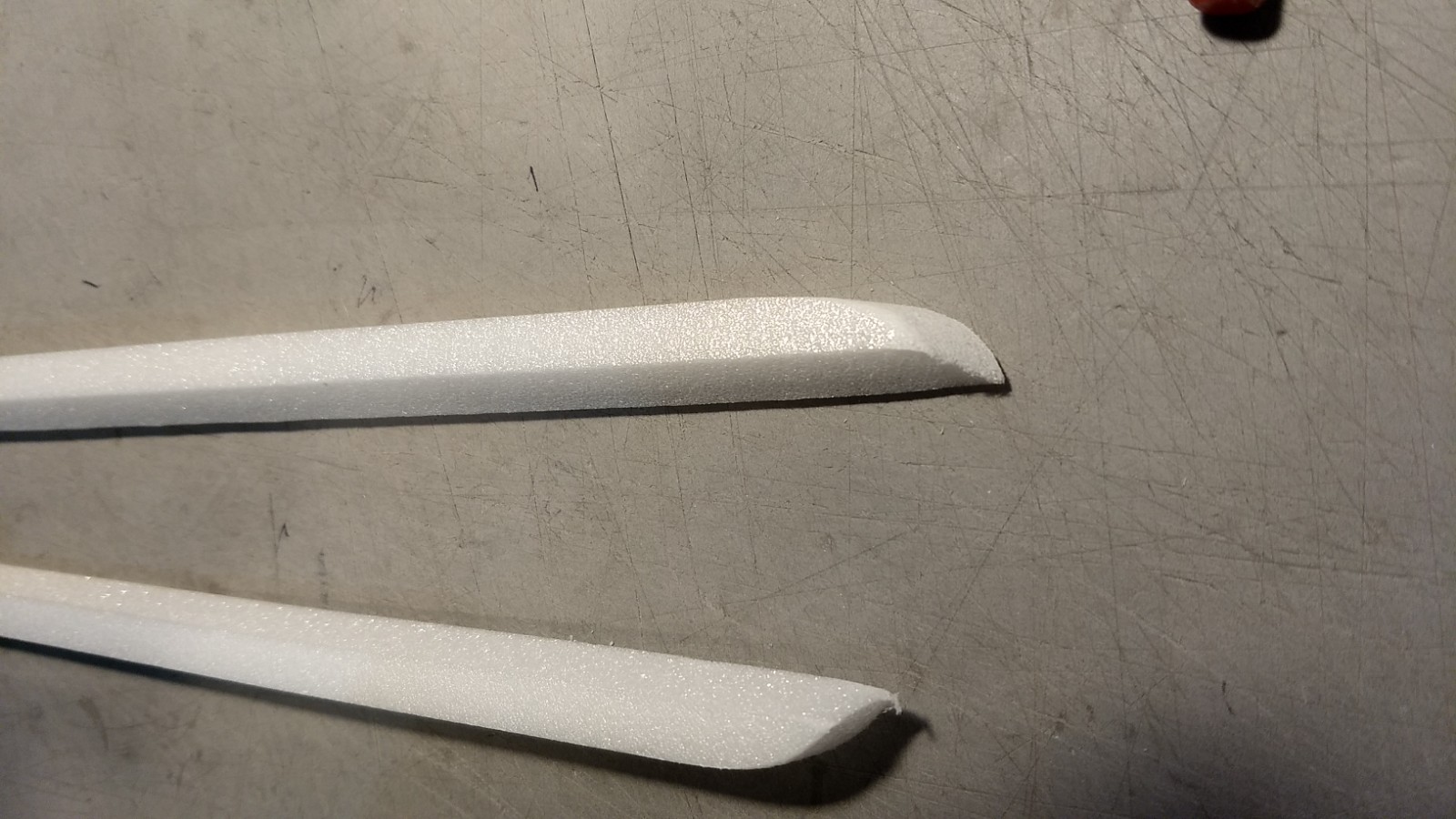
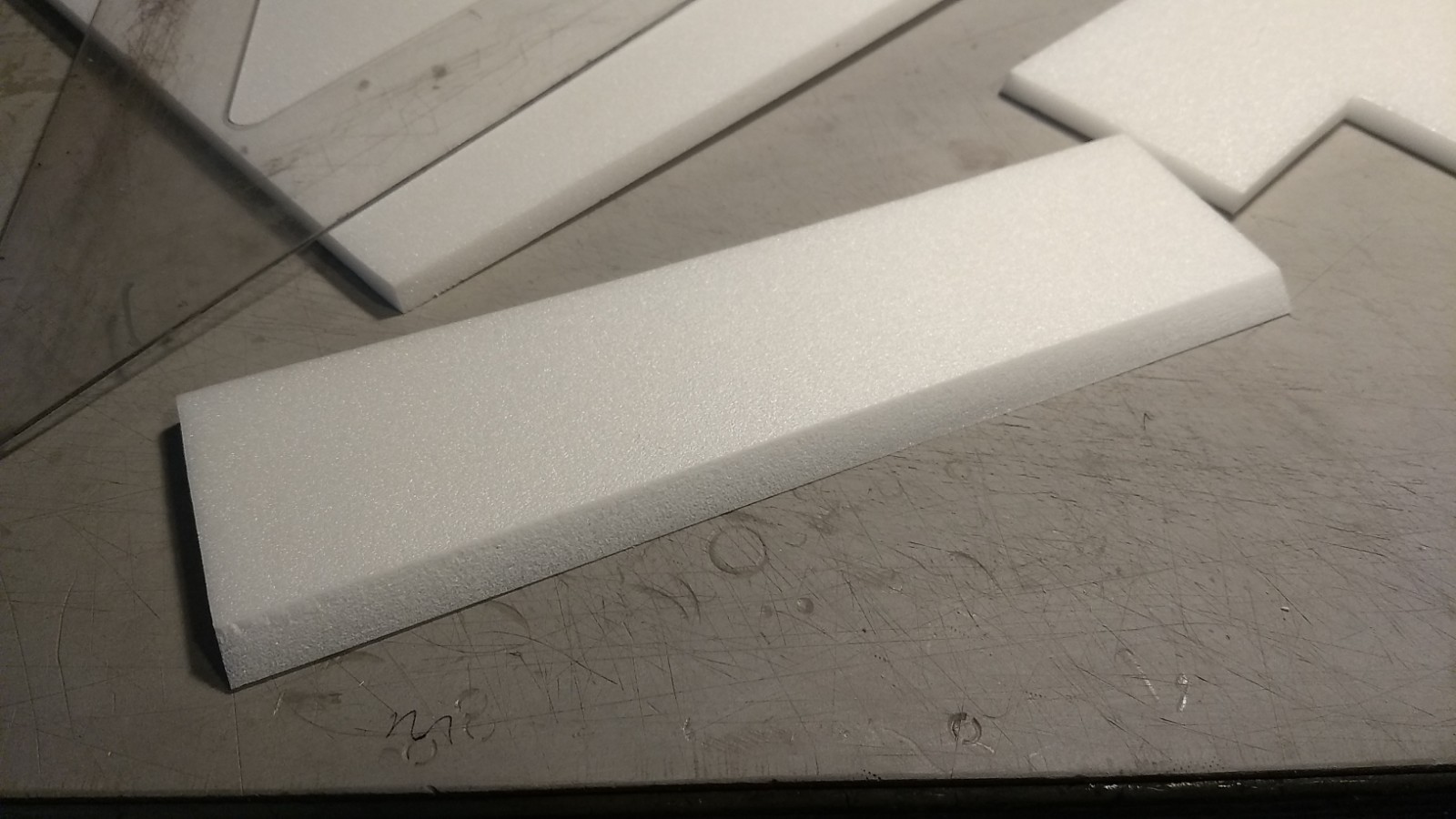
- Angle wing reinforcing strips cut and ends rounded.
-
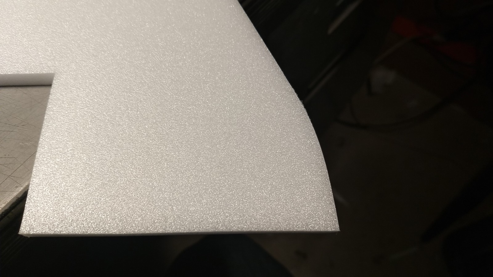
- wing tip radius
-
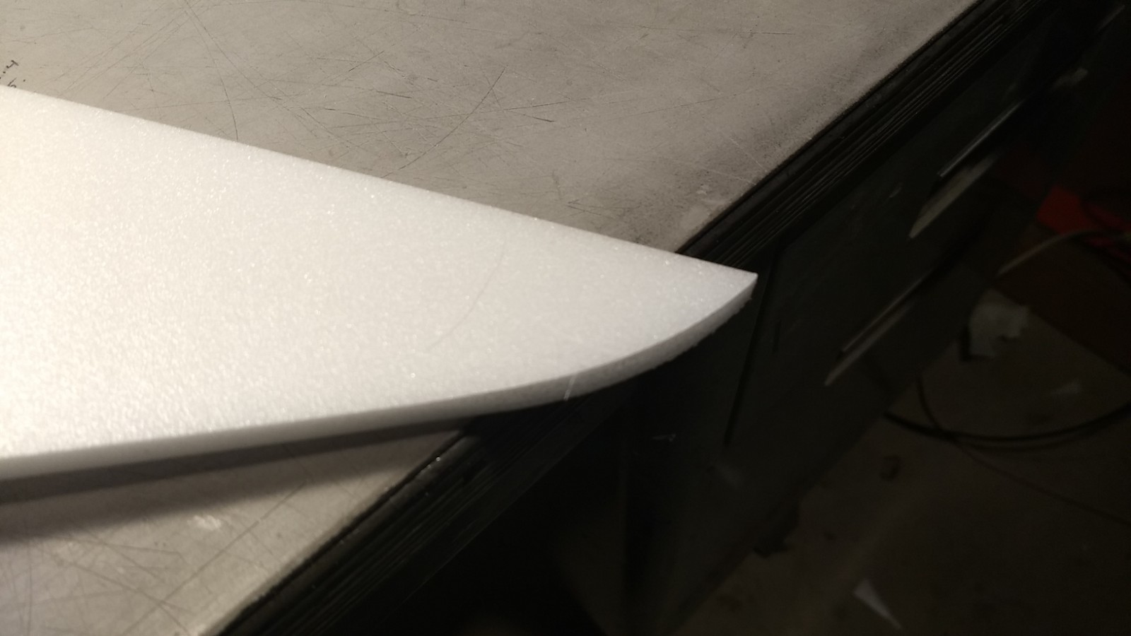
- Front of wing radius cut
-
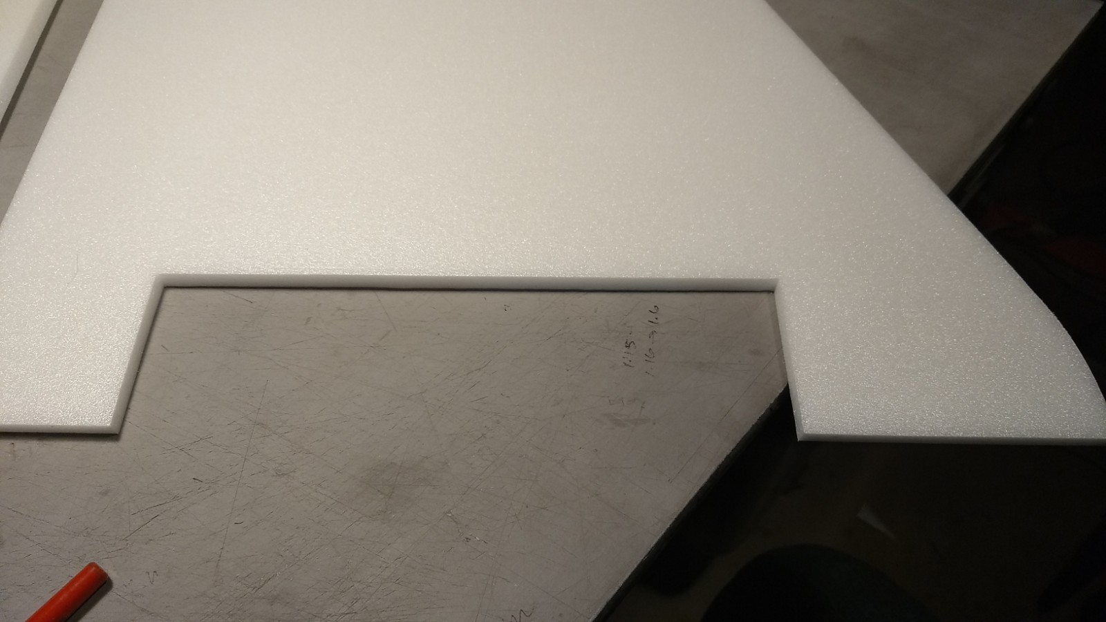
- Elevon cut out of wing
-
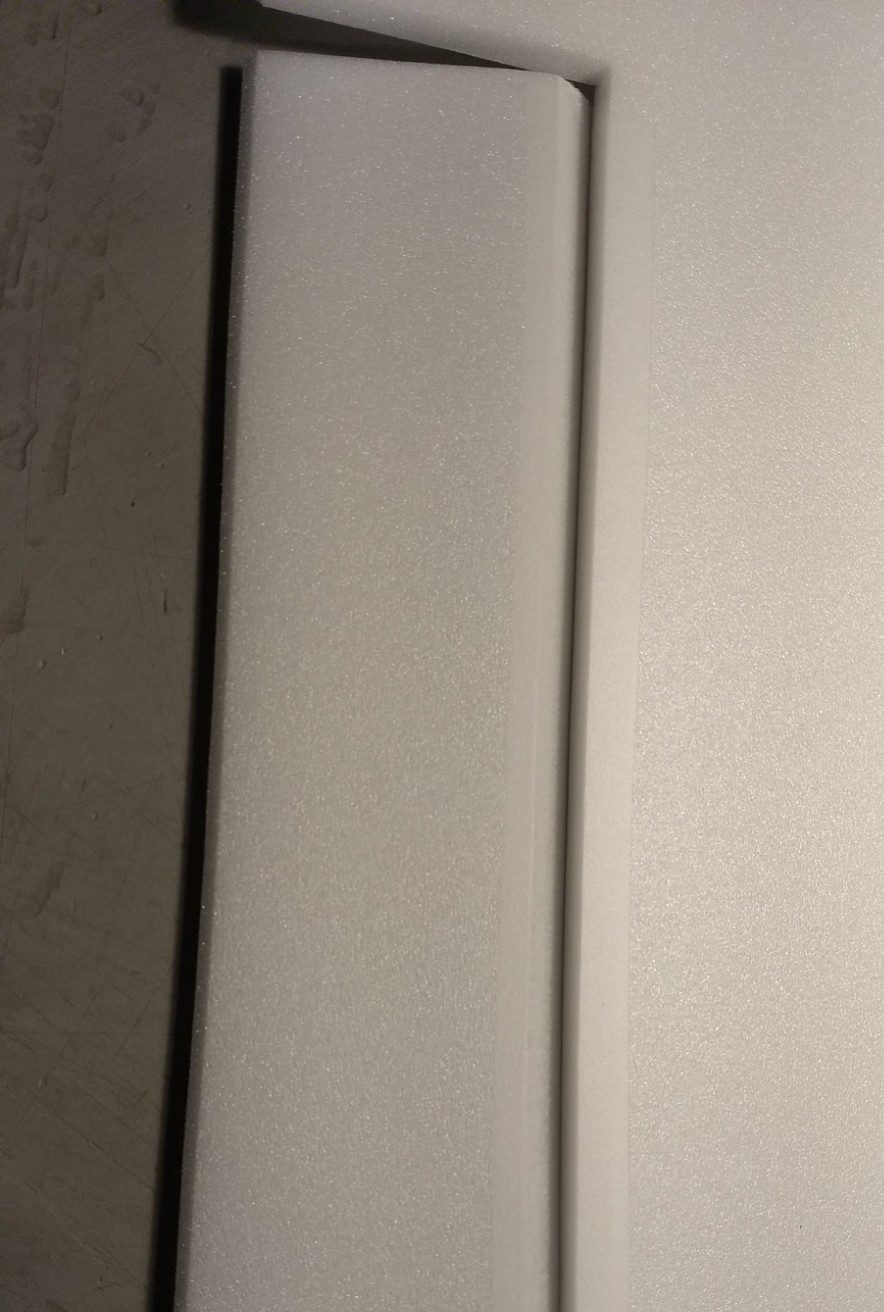
- 45 degree bevel cut on bottom leading edge of each elevon.
-
- Tape the top of the elevon hinge joint.
-
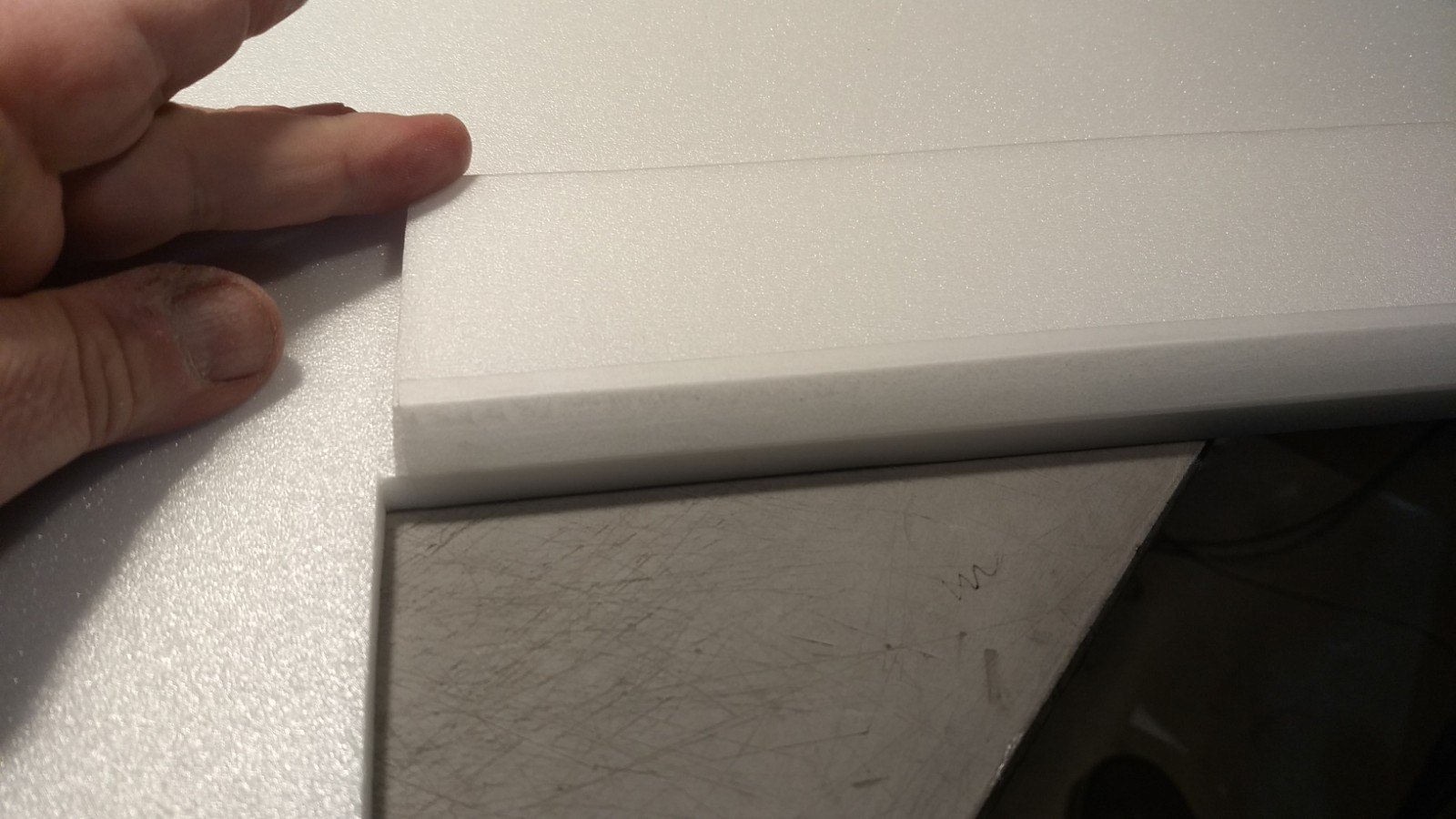
- Flip the elevon over on top of the wing and tape the bottom of the elevon hinge joint.
-
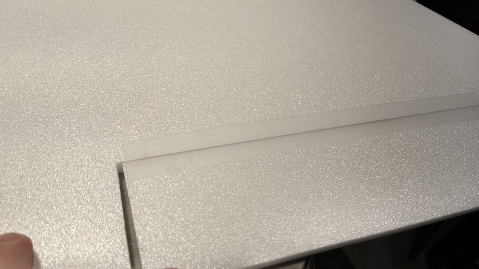
- Elevon installed and tape hinge applied.
-
- Showing the bottom of the elevon hinge joint
-
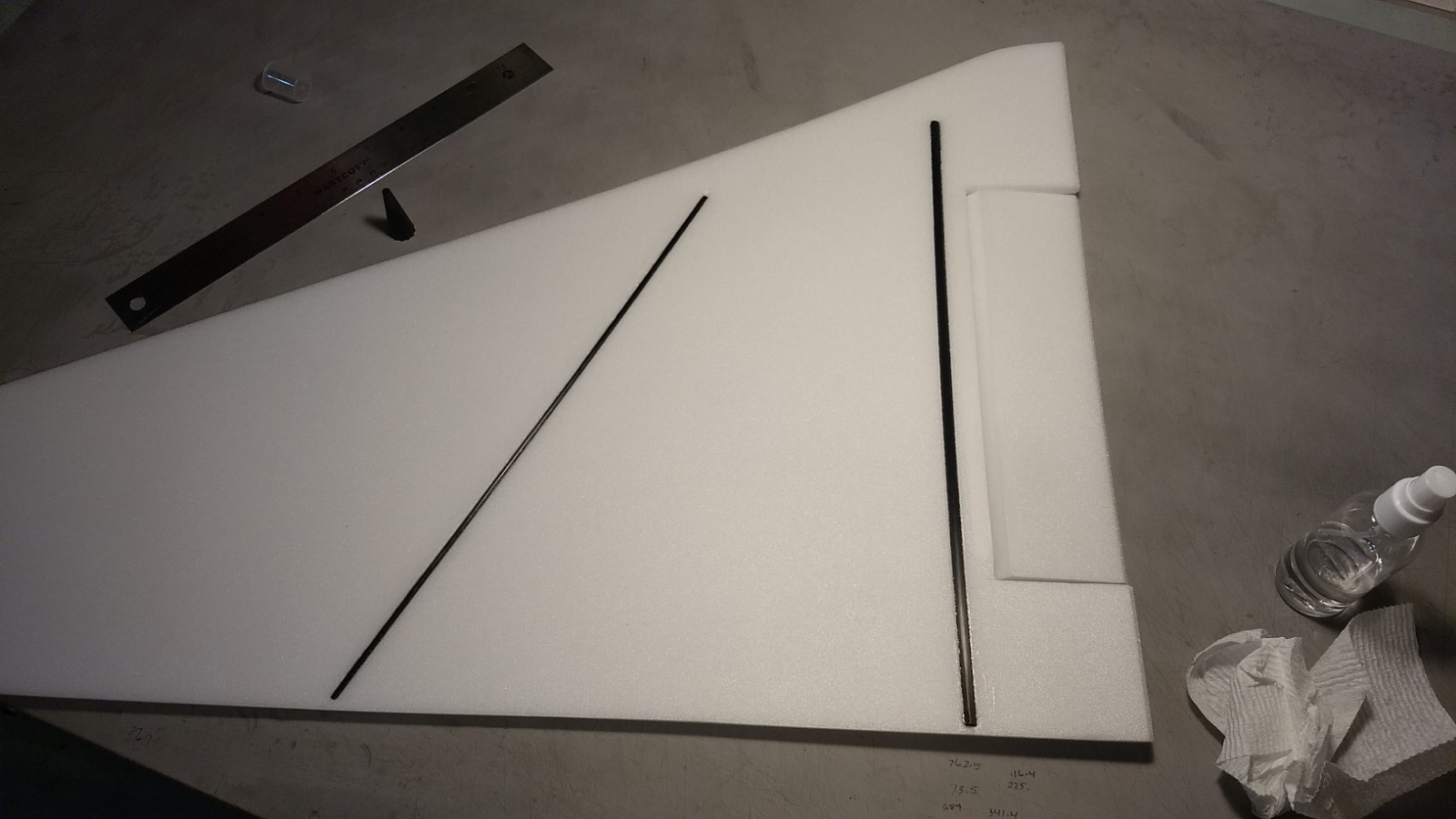
- Spars inset and glue into each wing half and taped over with blenderm tape.
-
- Spar installed in vertical stab
-
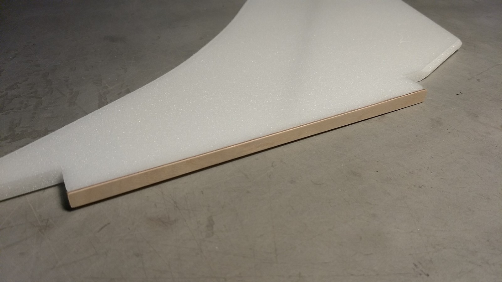
- Ply strip glued to vertical stab tab root edge.
-
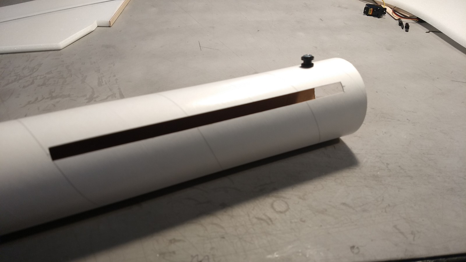
- Slot cut for vertical stab
-
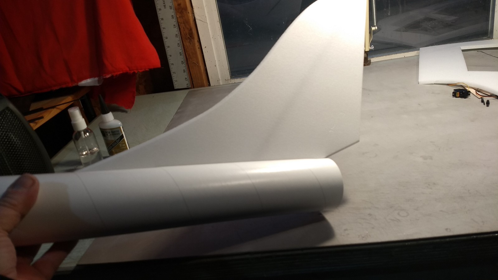
- Glue vertical stab in place.
-
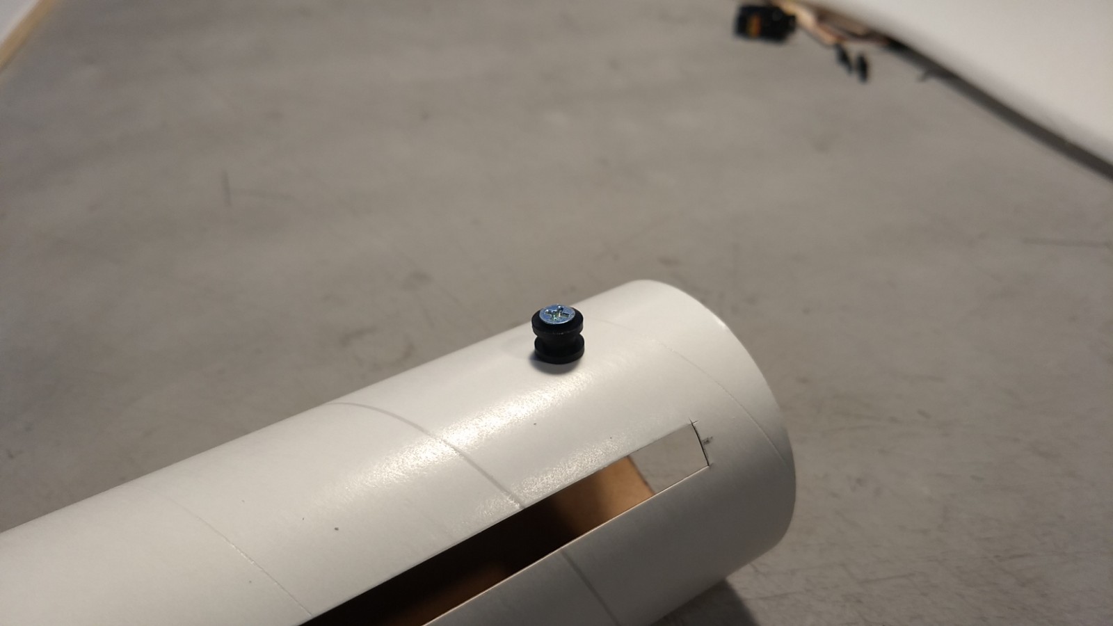
- Rear rail button installed.
-
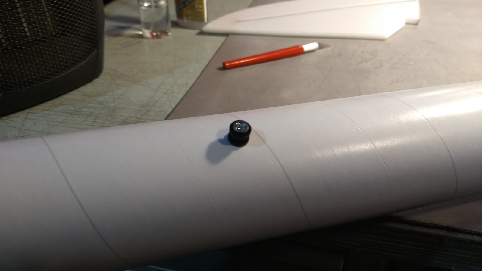
- Install rail buttons in the tube with the pre-punched holes.
-
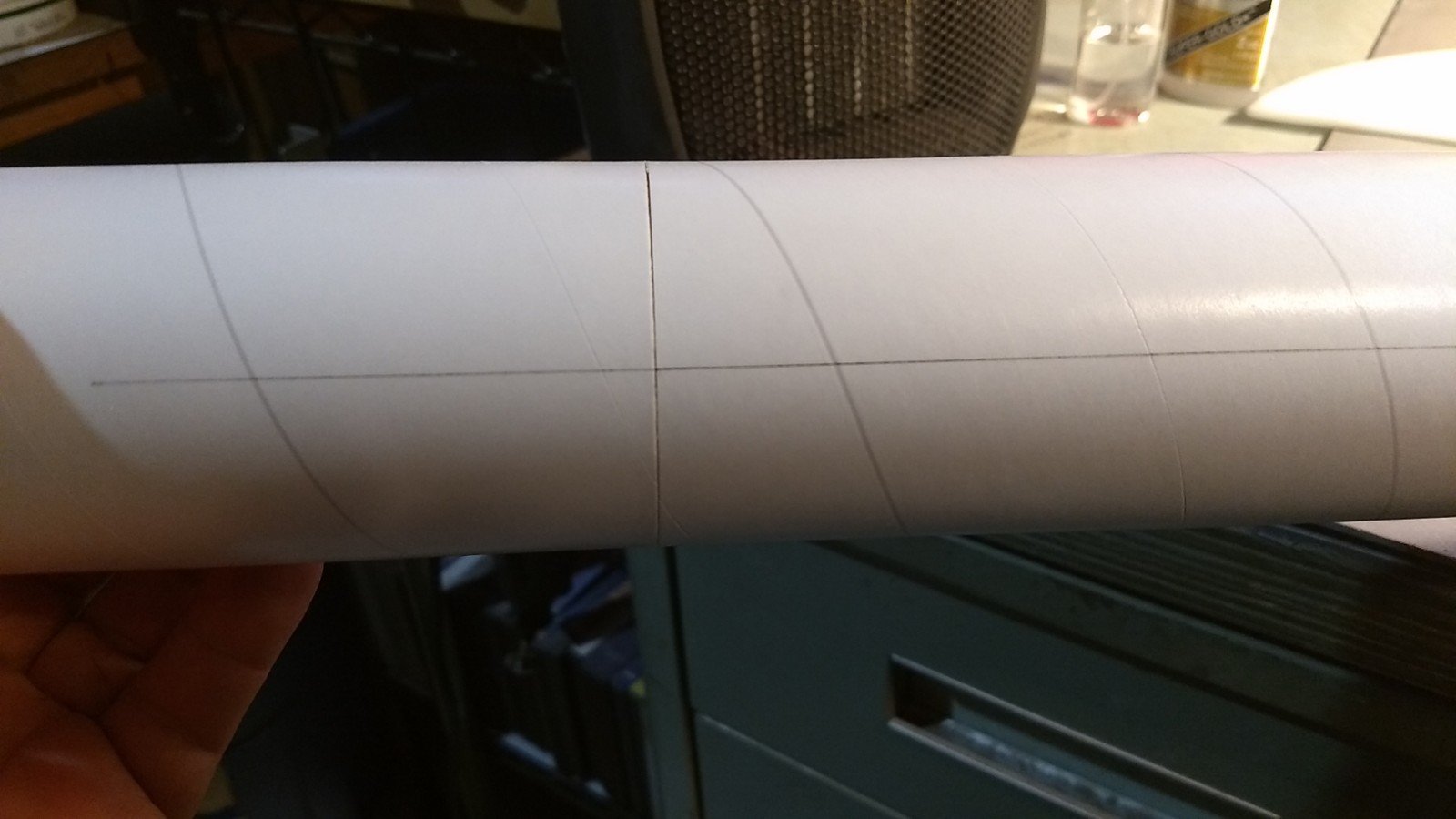
- Body tubes joined.
-
- Glue the wing to the bottom of the body tube on the lines marked with the rear even with the “rear” of the body tube. The wing should be even with the rear of the body tube.
-
- Prop up each wingtip the same amount, 1.5″ to 2.25″ or so and glue the stab in place keeping it vertical.
-
- Add foam reinforcing strips
-
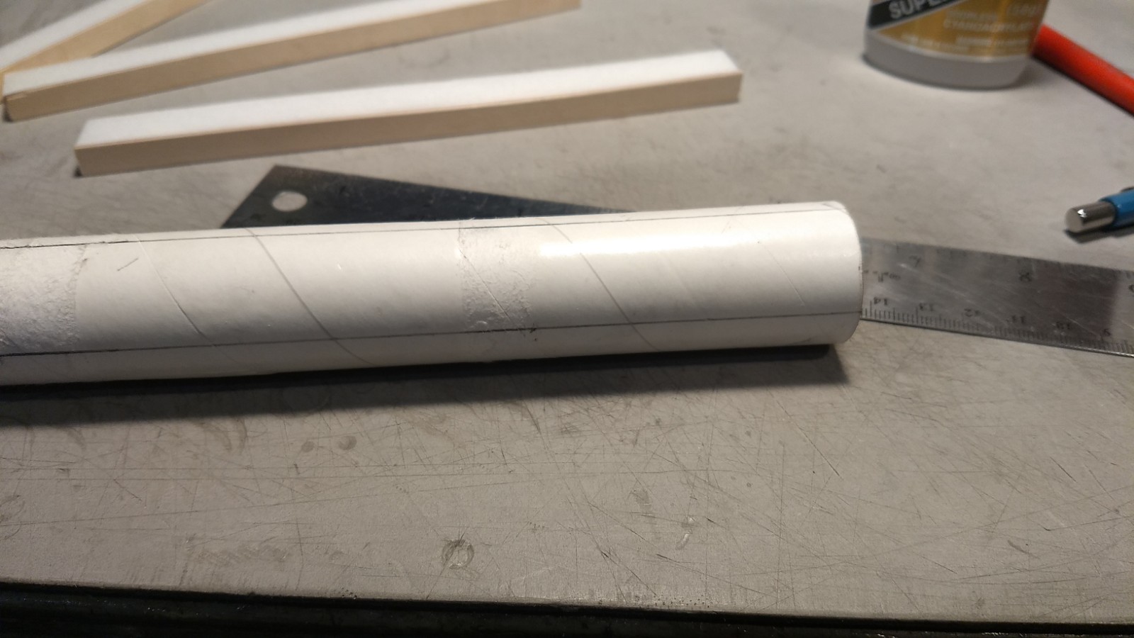
- Motor tube marked for centering strips.
-
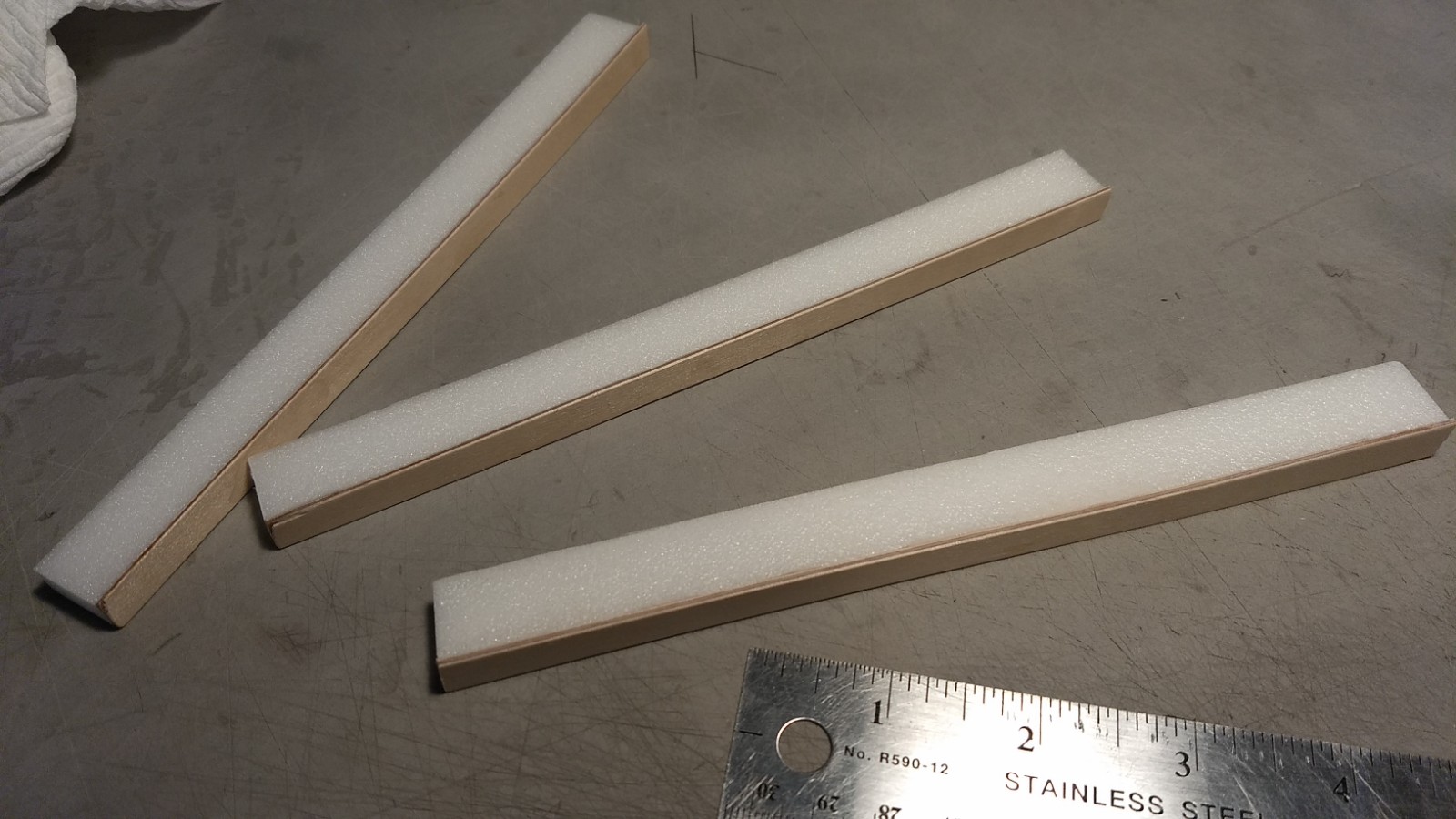
- 1/16″ basswood strips glued to each motor centering strip
-
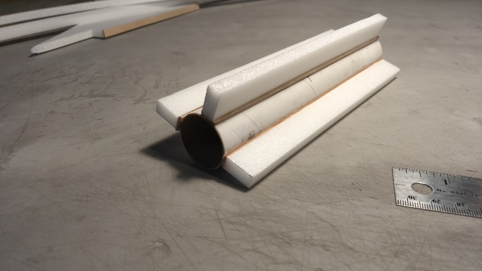
- Centering strips glued to the motor tube, ply plates glue to the tube.
-
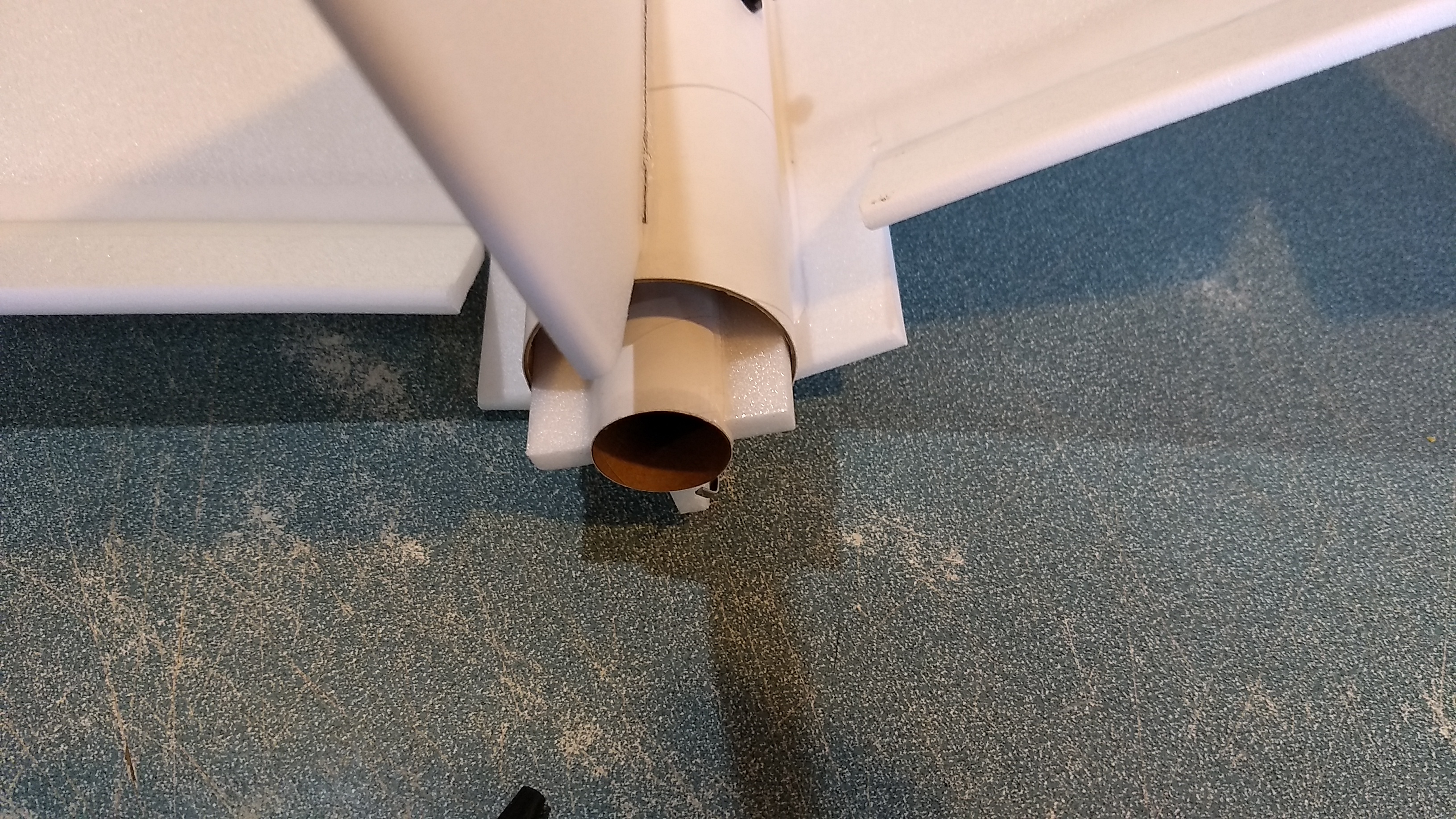
- Test fit the motor tube
-
- Example of how motor tube will look when installed and glue in place.
-
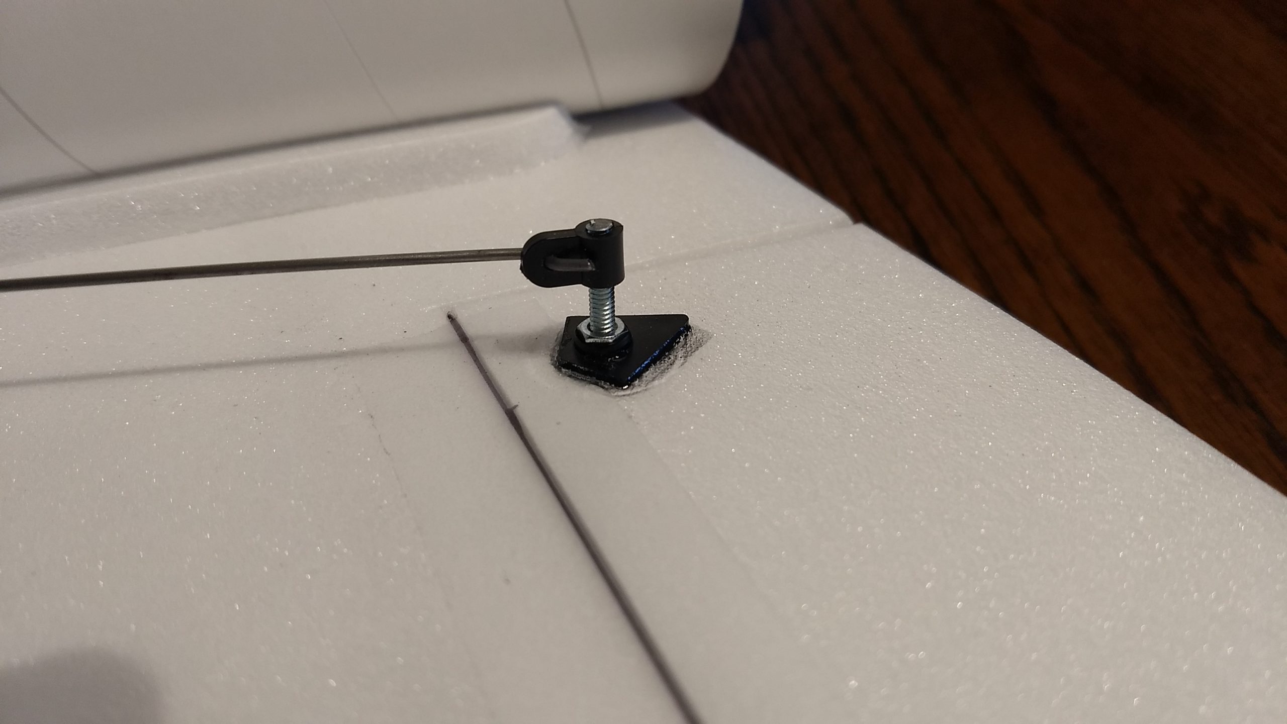
- Adjustable control horn installed
-
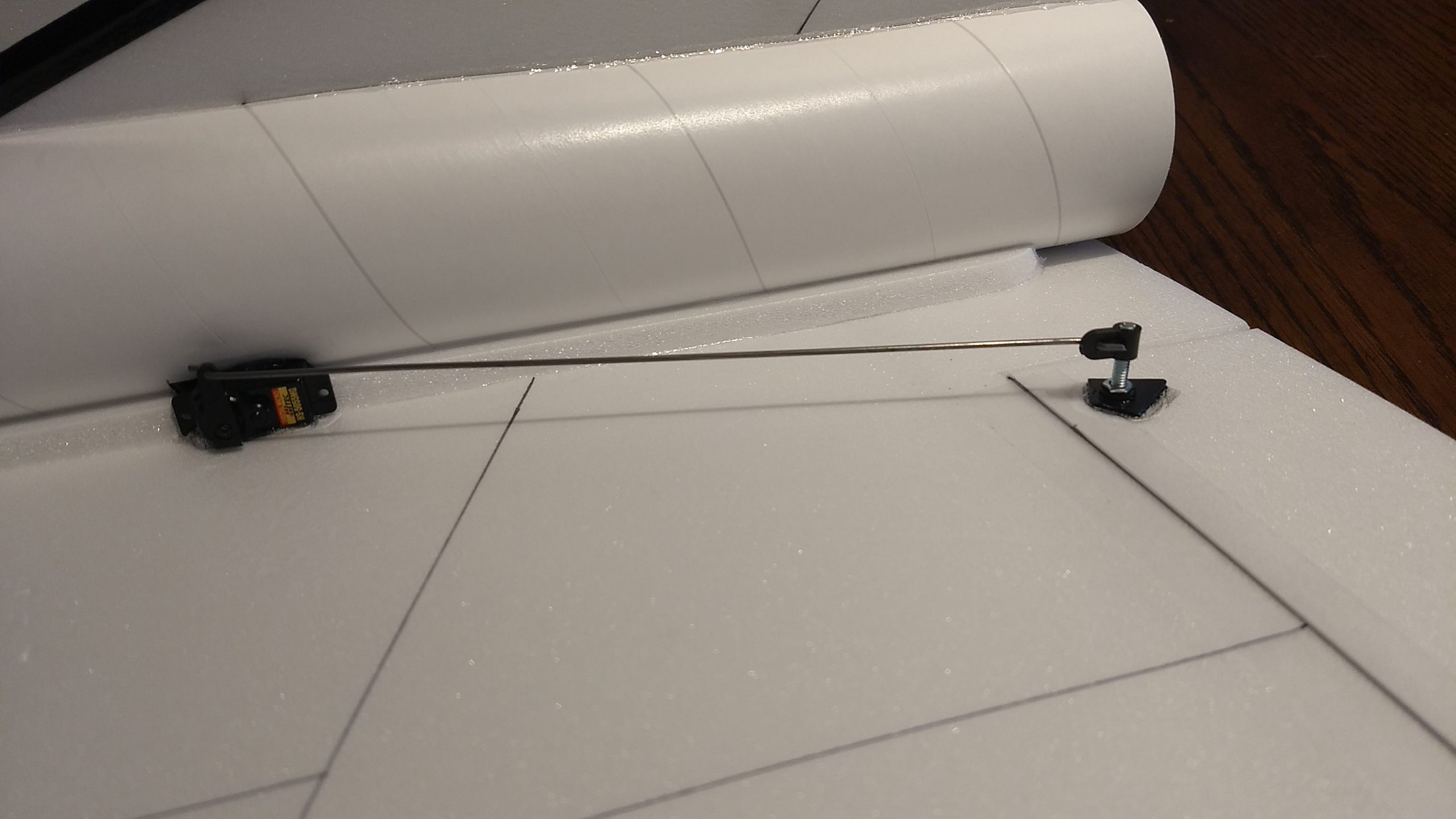
- Servo mounted in pocket cut into body tube.
-
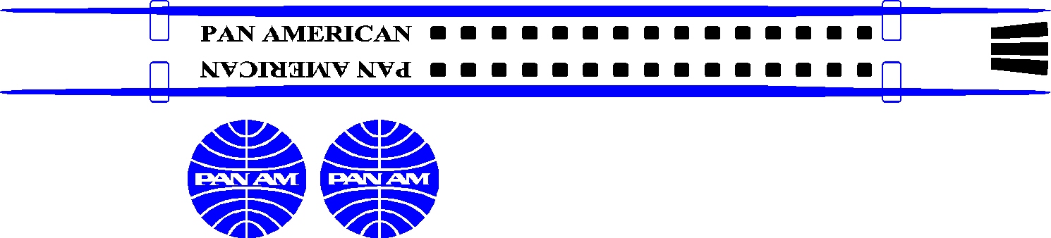
- example of stickershock decals
-
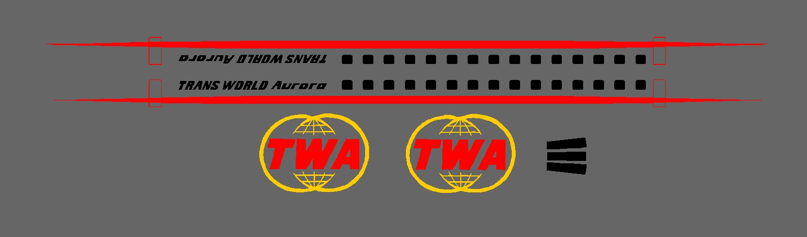
- example of stickershock decals
-
- Completed Model wtih custom Virgin Orbit Decals.
-
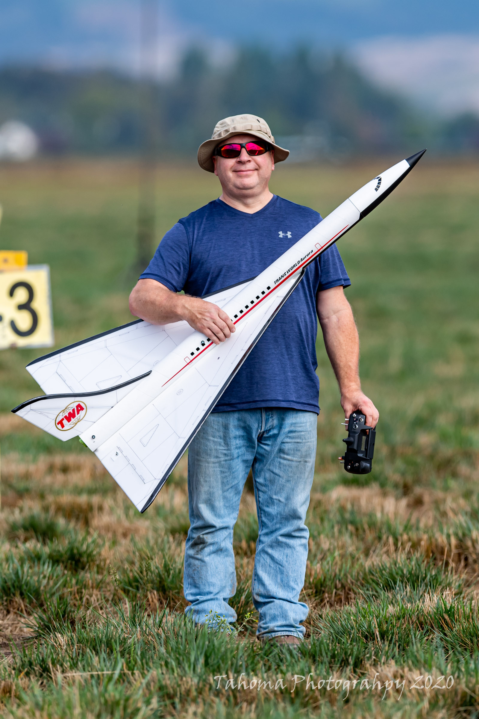
- Completed model with TWA Markings