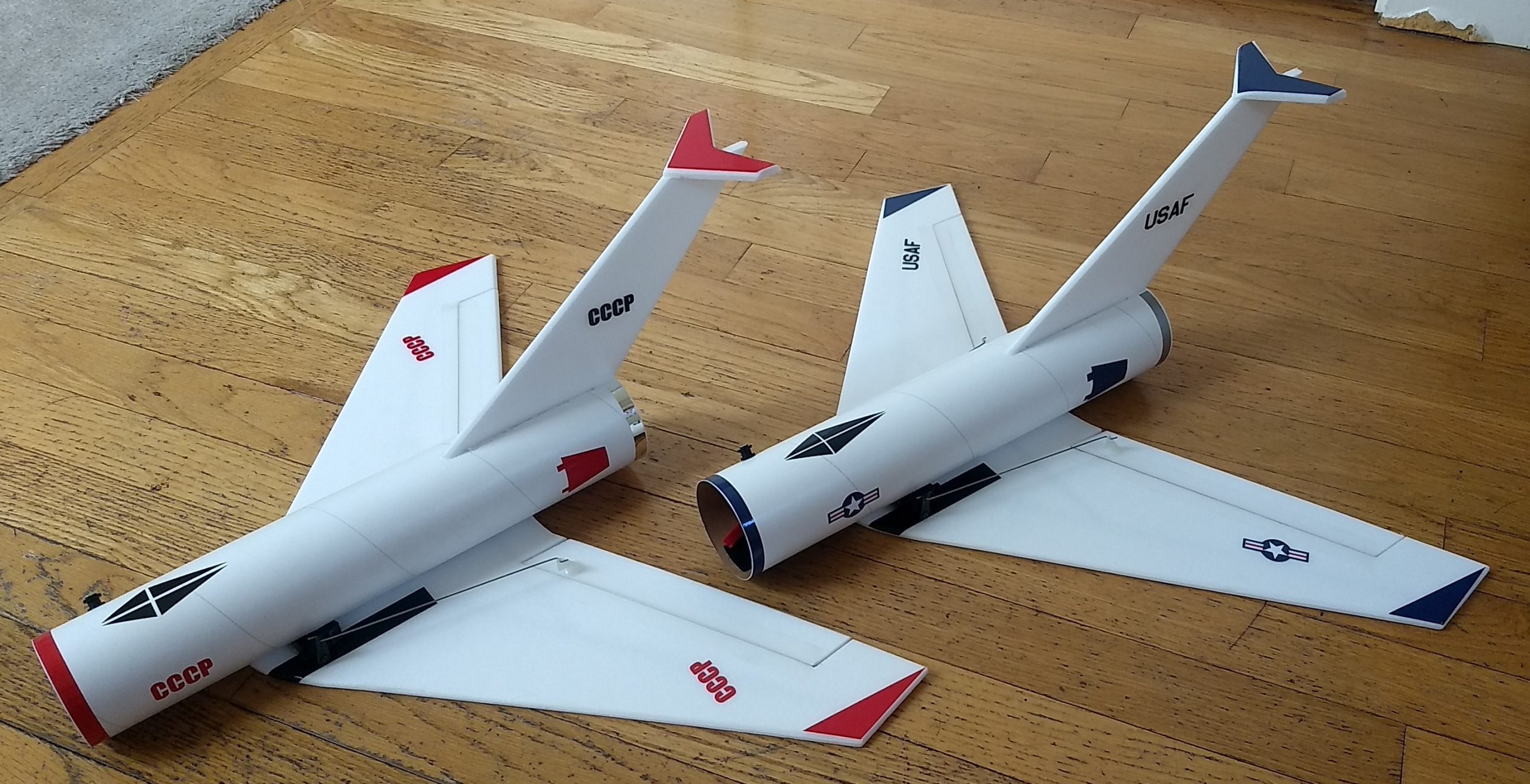
The Mock 10 RC Rocket glider kit is an homage to the old Centuri Mach 10 free flight boost glider. It is reminicsent of the early era Jet aircraft like the Mig 15 and F-86 sabre. The wing and tail are modified for R/C flight and nothing ejects from the model. It comes with 2.6″ white tubing for the body, 6mm Depron wing and tail surfaces. Elevons are pre-hinged, spars are already installed and the body tube is slotted for the tail and holes are pre-punched for the rail buttons. Construction is very simple. For 18mm Composite D2.3T and C 3.4T rocket motors only.
Please refer to the General information for all kits tab above, then read these instructions completely before starting assembly. High Quality cut vinyl decals will be available shortly in both a soviet and american version HERE
CG location for rocket flight should be 7.5″ from the front of the body tube. CG measured with loaded rocket motor in place and battery installed as it would be ready for flight.
Unpacking your kit:
The kits are packed to protect them in shipping, but the contents are fragile so unpack carefully. Carefully cut the tape holding the tubes in the box, then unwrap/lightly cut the plastic wrap to free the tubes, the spar may be packed in the tubes and the baggie with the little parts and nose cone will be in the tubes as well. Carefully cut the tape holding the cardboard wing protector in the box and carefully remove it, don’t pull hard or bend it. Then carefully cut the tape holding the cardboard top piece to the bottom. There may be some sticky tape holding the cardboard to the bottom cardboard piece, carefully peel it being sure not to bend anything. Once the top cardboard is free you can see the foam wing/tail parts, there are little fragile pieces in here, so unwrap carefully. It may be best to use an exacto to lightly cut the plastic wrap and carefully remove it without cutting into the foam. Make sure everything is free before you remove the pieces to avoid breaking anything. Kits contain one or two scrap pieces for repairs if you damage anything in construction or flight, just cut and patch in a spare piece of the foam if needed using foam safe CA+.
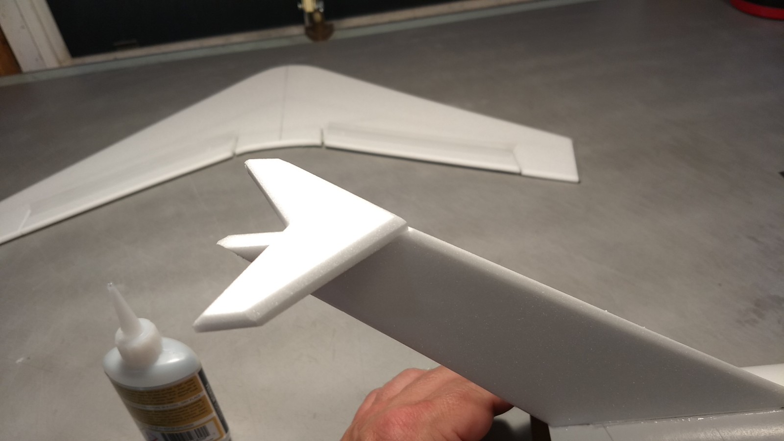
I beveled the edges of the flight surfaces with a straight edge and exacto knife, just a 1/16″ wide bevel on each side prior to assembly. It’s much easier than sanding and looks better than plain flat edges.
Welcome to the world of rocket boosted radio control gliders. This is not a model for a novice RC pilot, but anyone who is comfortable with RC flying of a medium speed model should be fine. Read through the instructions, look at the photos and be sure you understand the step before committing to cutting or glue.
Identify all pieces, the kit should contain:
1 wing
1 vertical stabilizer
1 horizontal stabilizer
2 control horns/Pushrods
1 Body Tube
1 9″ spar
Blenderm tape
Motor tube
Velcro(for battery and rx/bec attachment)
2 Rail buttons with t nuts/screws
Lead weight
Velcro
Battery adapter wires
Notes before starting:
Foam safe CA+, Bob smith super gold + is the only glue recommended for construction. You will also need foam safe accellerator to set the glue.
Assembly:
- In April 2022 the USPS raised shipping rates so this kit was re-designed to fit into a smaller shipping box. If your wing came as a single piece you can skip directly to step 2, if not do these two steps below:
- Unfold your wing and glue the taped wing joint.
- Glue the 9″ spar into the bottom of the wing in the pre-grooved slot, then tape over the spar with blenderm tape.
- Test fit then glue the vertical stab into the body tube. Apply glue to the bottom of the stabilizer root and press it against the bottom inside of the body tube keeping it lined up with the alignment line on the bottom of the tube.
- Once set apply a fillet of glue on the inside and outside of the body tube and stabilizer joints.
- Install the t nuts and rail buttons in the pre-made holes. The buttons are offset to the side so that they don’t get caught on anything when landing. A t nut goes on the inside, then a flat washer on the outside of the tube, the collar and another washer then the screw to hold them together, do not over tighten these.
- Apply glue the top center line of the wing(the side without the spars) and to the bottom wing line on the body tube. Set the wing in place keeping the front and rear marks aligned with the wing and tape the wing in place, then lay the wing flat on a table and use a triangle to make sure the stab/body tube is perpendicular to the wing while the glue sets. Once set apply small dots of glue into the wing/body tube joint every half inch or so to make sure the wing is securely glued to the body tube and make sure it is set before continuing.
- The motor tube has two lines on it, you will slip it into the slot in the vertical stab tab and put one line on the top left of the stab and the lower line on the bottom right of the stab slot. This will ensure the tube is centered in the slot. Make sure it is straight and then run a fillet of CA down each side and make sure it is set before continuing.
- Glue the horizontal stab to the top of the vertical stab even with the front and make sure it is perpendicular to the stabilizer.
- Glue the control horns/pushrods into the top of the elevons with CA+ in the pre-made holes. The pushrods should be on the inside of the control horn closest to the body tube and angle inward toward the body tube. Make sure these are installed securely. Once set apply a little glue on the prongs on the bottom of the elevons to lock the horns in place.
The basic construction is now complete.
Radio Installation
Note: Your radio needs to be configured for Delta mixing, this means that the servo arms will move the same direction during elevator stick movement and opposite for aileron stick movement. Connect your servos to the receiver one in the aileron connection and one on the elevator connection and apply power. Use a servo arm at least 9/16” long and with holes small enough that there won’t be slop with the pushrod wire when installed. I use the hole furthest out on the servo arm, to maximize movement. On some servos there are a long two-ended servo arm, you can trim off one end if needed to get sufficient length. Zero out any trim settings on the transmitter. The model once the motor has burned out is nose heavy and flying wings lose pitch authority when nose heavy so you want as much up elevator travel for trim/flare as possible.
- Use the general instructions tab above to assemble the battery adapter wire for the 500mah battery with jst connector. If you are using a different battery make up an adapter to fit your battery connector to the battery input of the receiver.
- Bind and power up the receiver.
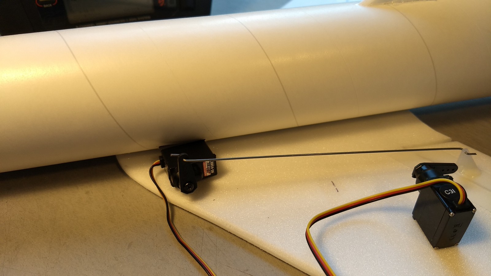
- Connect a servo to each pushrod, the servo wire should be closest to the center and the output shaft is outboard toward the wing tip. If the wire is too tight, you can use twist an exacto knife in the servo arm hole to make it larger, but be careful and do not make it too large. Once connected, tape each servo in place on the top of each wing so that the control surfaces are centered. Look at the model from the rear. Moving the transmitter stick back(up elevator) should move both elevons up. Moving the transmitter stick to the right should move the right elevon up and the left elevon down. If you can’t get the servo reversing to give you the right polarity try swapping aileron/elevator inputs to the receiver or turning the servos over and swapping the servo arms to the other side of the output shaft. If that is correct, continue.
- Mark where the servos contact the body tube and cut a pocket into each side of the body tube so that the servo can inset slightly and route the servo wire into the body tube and out the front and re-connect to the receiver.
- The servos are attached to the model by directly gluing the servo to the wing with CA+ or a small amount of epoxy. Double back servo tape can loosen over time and with exposure to heat, I prefer to glue the servo in place. With the radio still on, put a small amount of glue on the servo, being careful not to get any near the output shaft. And set it in place on the model keeping the control surface centered. Do the same to the other side. Make sure the glue is set before continuing.
- Make sure the control surfaces are centered, use trims if needed. Now measure the control surface movement. Full elevator movement should be 5/8″ to 3/4” in each direction, aileron movement should be 3/8″ in either direction. Since the model will be nose heavy, elevator elevon movement helps to give sufficient authority during glide.
- If you have a flap/elevator mix or flight modes you can program up elevator to a switch setting. The model needs approximately 1/4-5/16” of UP elevon during glide to start, and neutral elevon for boost(for first flights) If you can’t set the up elevator trim to a switch on your radio you’ll have to manually put in glide trim which is hard to do while flying the model. (On my spectrum dx8 using hs65hb servos, 60% aileron and 125% elevator dual rate settings, the elevator flap setting was 0 for boost and +29 for glide.)
- Use the included Velcro to attach the receiver and battery to the model at the front inside bottom of the body tube. This allows you to be able to remove and replace the receiver if needed for repairs or for removing the servo wires.
- Insert your heaviest loaded rocket motor into the motor mount
- Support the model upside down at the balance point indicated for boost. I use two pencils with the eraser pointed up and held in place with a small hand vice. Place the model on the pencil erasers on the balance point indicated above. If necessary glue some of the lead weight at the front or rear of the model to balance it as needed or move the reciever/battery around slight. I found by removing the plastic casing from the AR-410 receiver I did not need any weight for it to balance perfectly.
- Do not try to fly the model with it balancing it behind this point. The adage is, a nose heavy model flies poorly, a tail heavy model flies once.
- If you use the stickershock decals, once applied use a hair dryer on hot to soften the decals on the foam and press them down lightly to securely set them into the foam surfaces.
Flying: See the Instruction/Information link at the top for flying instructions Be ready on the first few flights to keep the model straight till you have the trims set perfectly.
-
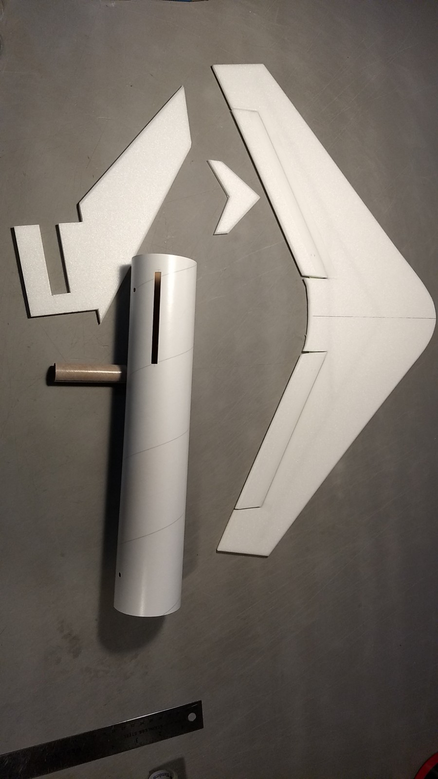
- Major Kit parts.
-
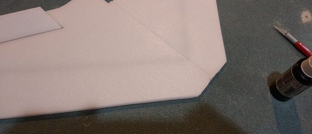
- If your wing is not a single piece, glue the taped joint and lay flat to cure
-
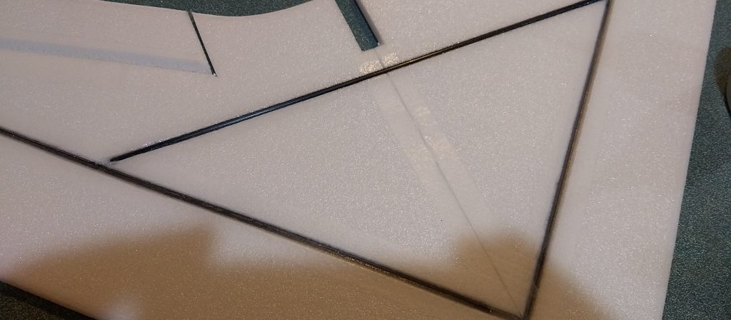
- Flip the wing over, glue the short cross spar in the pre-grooved notch and then tape over with blenderm tape.
-
- Glue in vertical stab.
-
- Glue in motor tube.
-
- Wing glued in place using reference marks and keeping vertical stab perpendicular to wing.
-
- Install Rail Buttons
-
- Glue horizontal stab in place.
-

- Completed airframe
-
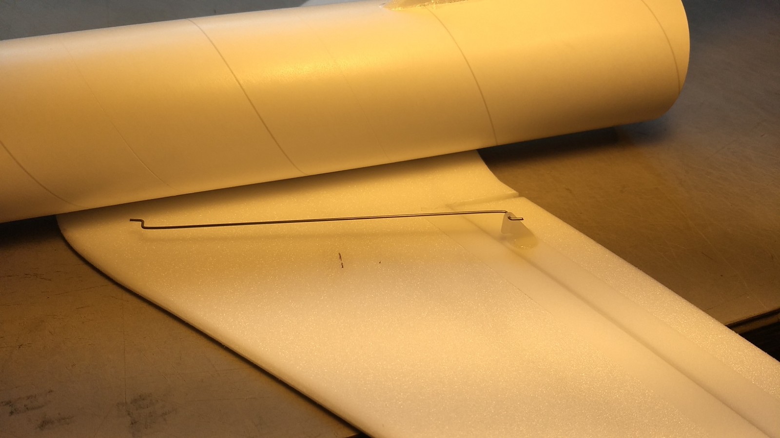
- Glue the two pushrods/horns in place, with pushrod closest to body tube and pushrod will angle in slightly.
-
- Put glue on prongs on bottom of surface to lock the horns in place.
-
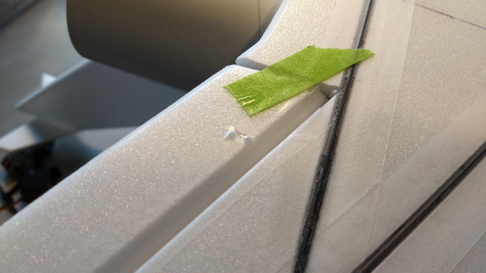
- Test fit servos and mark for servo pockets on body tube.
-
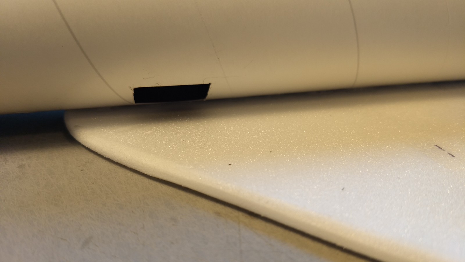
- Cut pockets for the servos.
-
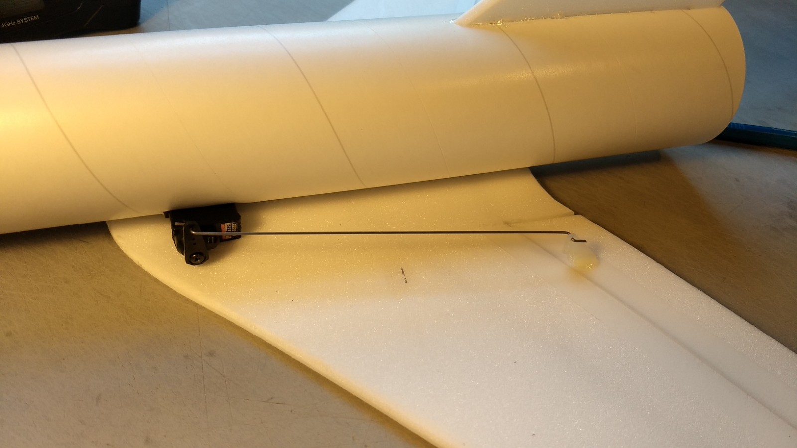
- Glue servos in place.
-
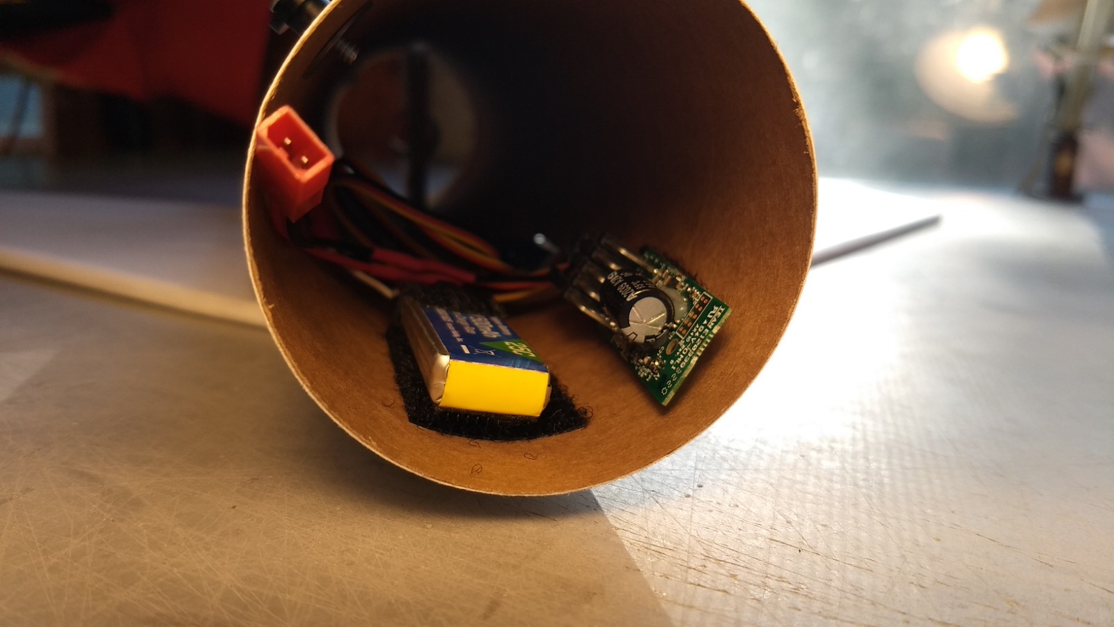
- Mount battery and receiver with velcro at the front of the body tube.
-
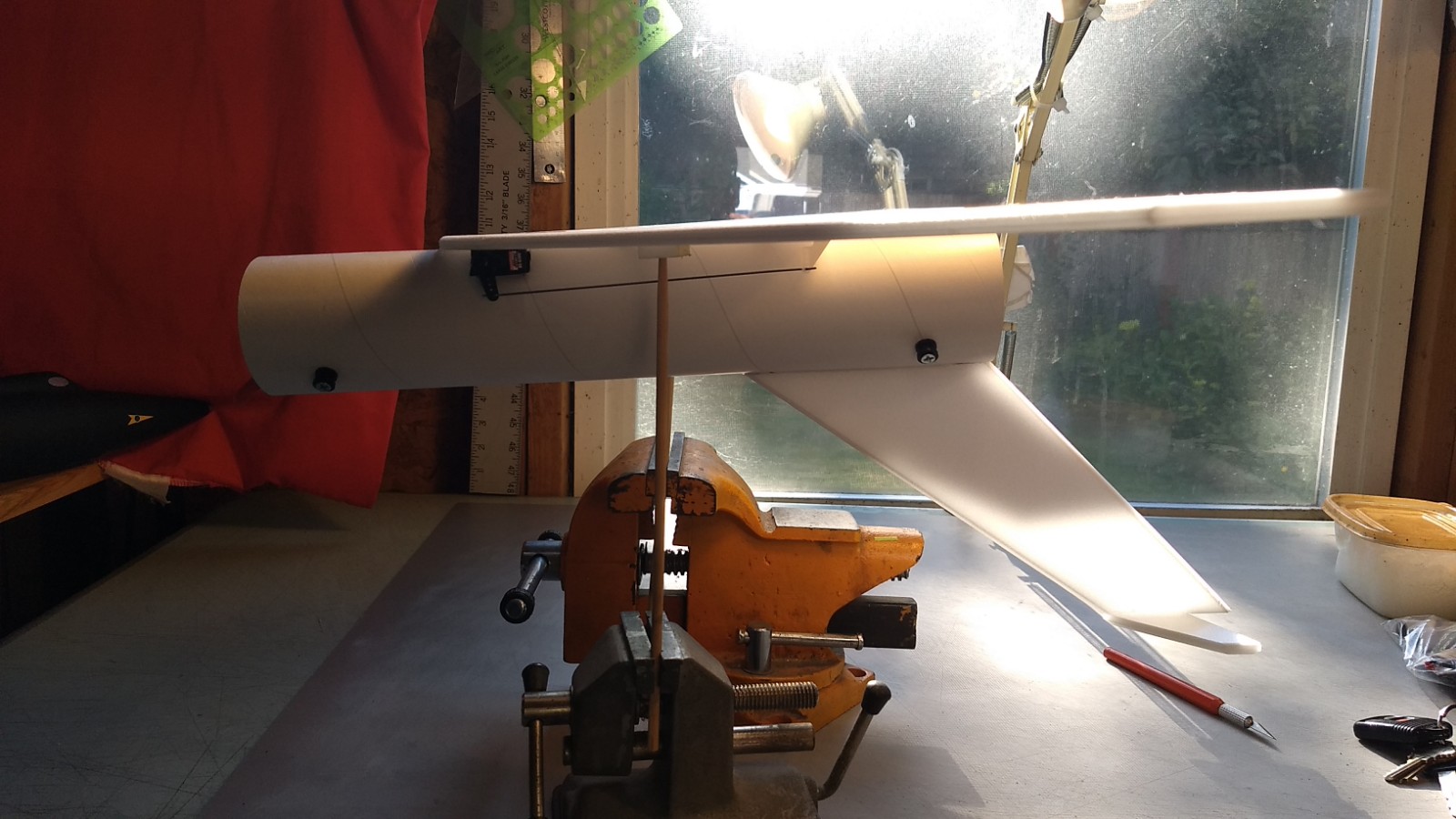
- Balancing the model.
-
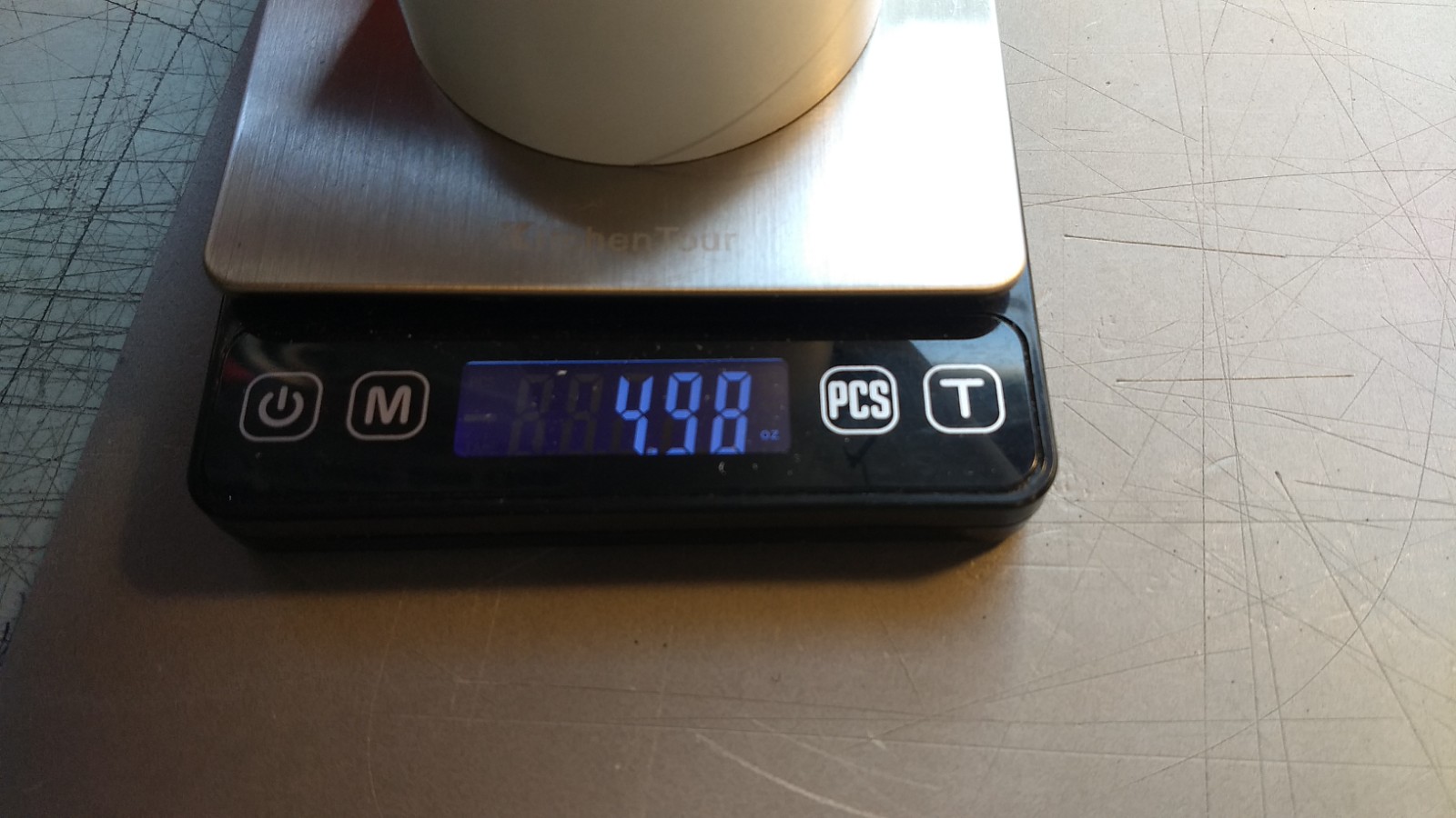
- Ready to fly weight, 4.98 oz.
-
- Completed models shown with both soviet and US versions of the stickershock decals.
-

- Example of stickershock Decals, Soviet or US style