The F-22 Raptor RC Rocket glider kit is based on the world beating stealth air superiority fighter. It features a high mounted wing with spars pre-installed, a plastic nose cone, 2.6″ white tubing for the body and depron wing and tail surfaces. Elevons are pre-hinged. The body tube end is pre-cut at an angle and the rail buttons holes are are pre-punched. You will need two 10 gram type servos, a receiver, and a small 500mah single cell lipo battery. you will need one 12″ servo extension for the battery wire to reach inside the nose cone. You will need a transmitter with delta or elevon mixing. Specs: 31″ length, 20″ wingspan, 9.5 oz rtf, for 24mm E-6 single use or reloadable motors.
CG location for rocket flight with battery and loaded motor installed: 7 7/8″ to the rear of the front of the body tube.
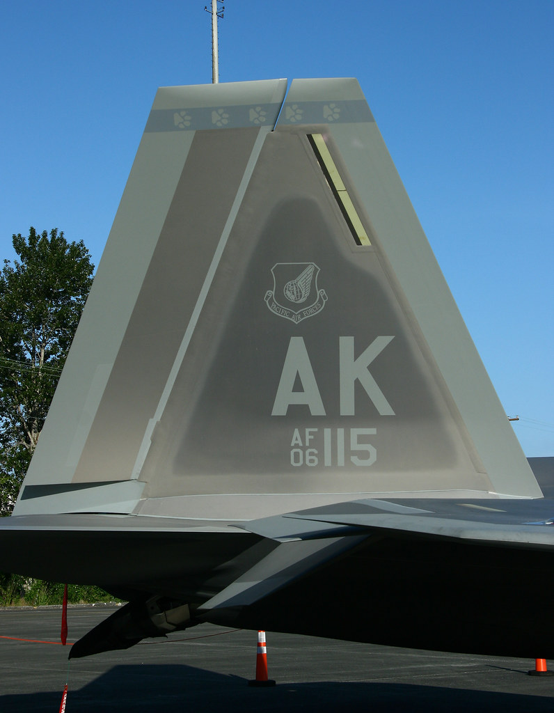
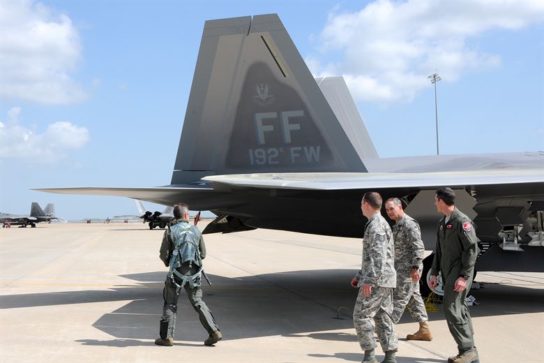
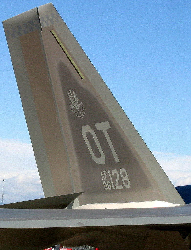
High quality cut vinyl decals are available in your choice of tail markings HERE:
Please refer to the General Information Link above then read the instructions completely before starting assembly. The assembly photos are for general reference but may not include every step in the instructions. If you want hardcopy to work from, all you have to do is click/drag/select and copy all of the text below, open word and paste with “keep original format” and it looks exactly like it does online then you can print it.
Unpacking your kit:
The kits are packed to protect them in shipping, but the contents are fragile so unpack carefully. Carefully cut the tape holding the tubes in the box, then unwrap/lightly cut the plastic wrap to free the tubes, the spar may be packed in the tubes and the baggie with the little parts and nose cone will be in the tubes as well. Carefully cut the tape holding the cardboard wing protector in the box and carefully remove it, don’t pull hard or bend it. Then carefully cut the tape holding the cardboard top piece to the bottom. There may be some sticky tape holding the cardboard to the bottom cardboard piece, carefully peel it being sure not to bend anything. Once the top cardboard is free you can see the foam wing/tail parts, there are little fragile pieces in here, so unwrap carefully. It may be best to use an exacto to lightly cut the plastic wrap and carefully remove it without cutting into the foam. Make sure everything is free before you remove the pieces to avoid breaking anything. Kits contain one or two scrap pieces for repairs if you damage anything in construction or flight, just cut and patch in a spare piece of the foam if needed using foam safe CA+.
Welcome to the world of rocket boosted radio control gliders. This is not a model for a novice RC pilot, but anyone who is comfortable with RC flying of a medium speed model should be fine. Read through the instructions, look at the photos and be sure you understand the step before commiting to cutting or glue.
F-22 Raptor Rocket glider instructions
Identify all pieces, the kit should contain:
1 wing taped together
1 Nose Cone
2 vertical stabilizers/intake plates
2 control horns w/pushrods
2 2.75″ beveled motor tube supports
1 Body Tube
Motor mount
4 cockpit pieces.
Velcro(for battery and rx/bec attachment)
Lead weight
Spare depron
Notes before starting:
Reference to glue, CA, or CA+ means foam safe CA+, normal CA+ will melt the foam! Normally you need to use accelerator to get the CA to set on the foam since there is nothing for it to soak into and activate.
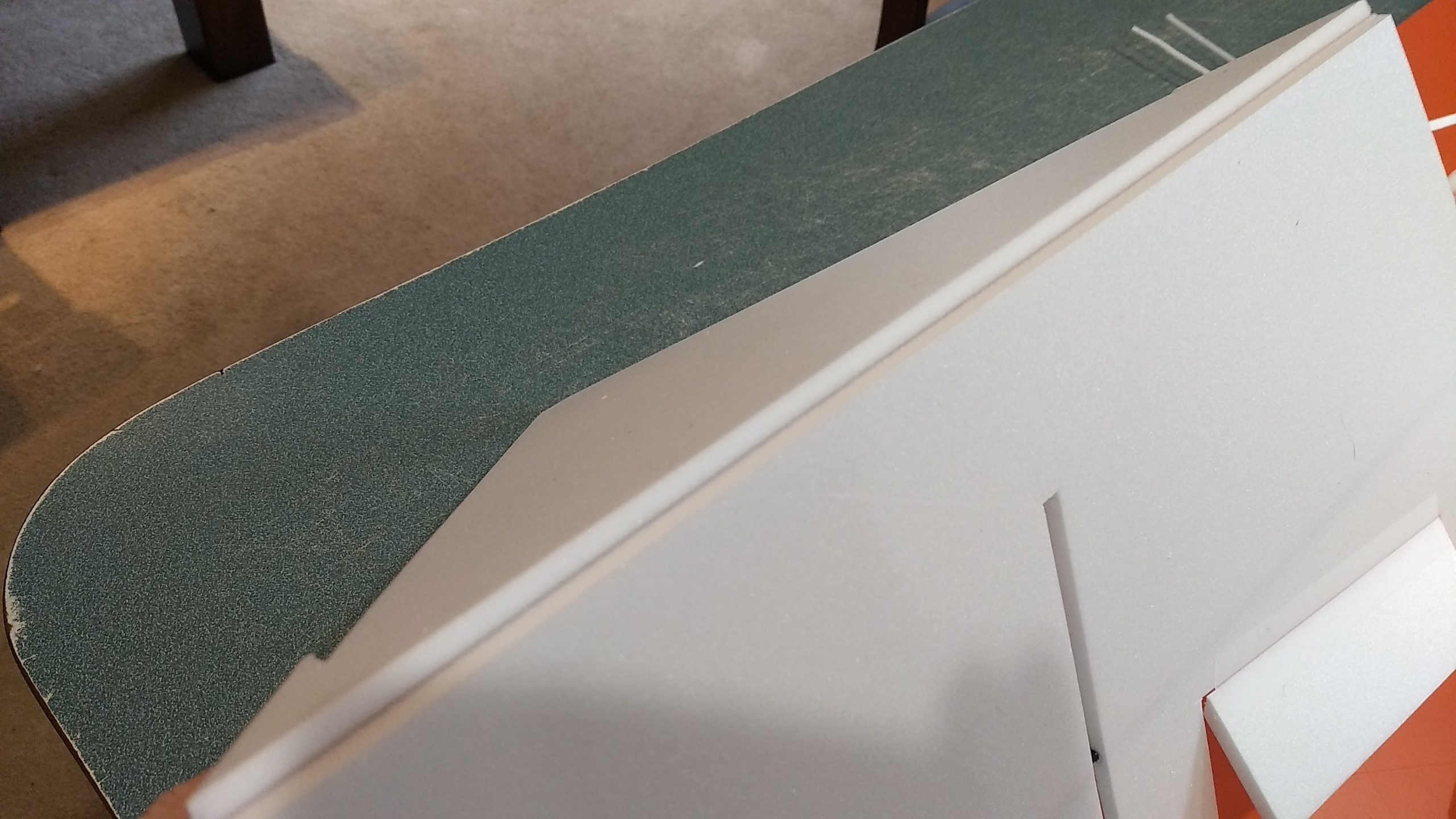
I used a thin straight edge and sharp exacto to bevel the leading and trailing edges of the wing and tail surfaces and vertical stabilizers before assembly, just a light 1/16″ 45 degree bevel on the top and bottom.
Epoxy is not needed in this model. Weight is critical and the model is designed for the thrust and flight loads.
Assembly:
- Unfold the wing and apply glue to the wing at the taped joint and set it on a flat surface to dry face up. Then flip the wing over, the bottom of the wing will have the spar visible.
- Lightly sand the fuselage wing line and apply a squiggle of glue about 1/2 wide to the body tube wing line.
- Lay the body tube on the wing using the front center of the wing and the rear line on the inside of the tube as a guide. The front of the body tube should be even with the front of the wing. Make sure it is set before continuing. Once set apply a few dots of glue on each side of the joint at the front, rear and middle and make sure the wing is well attached to the tube the entire length before continuing.
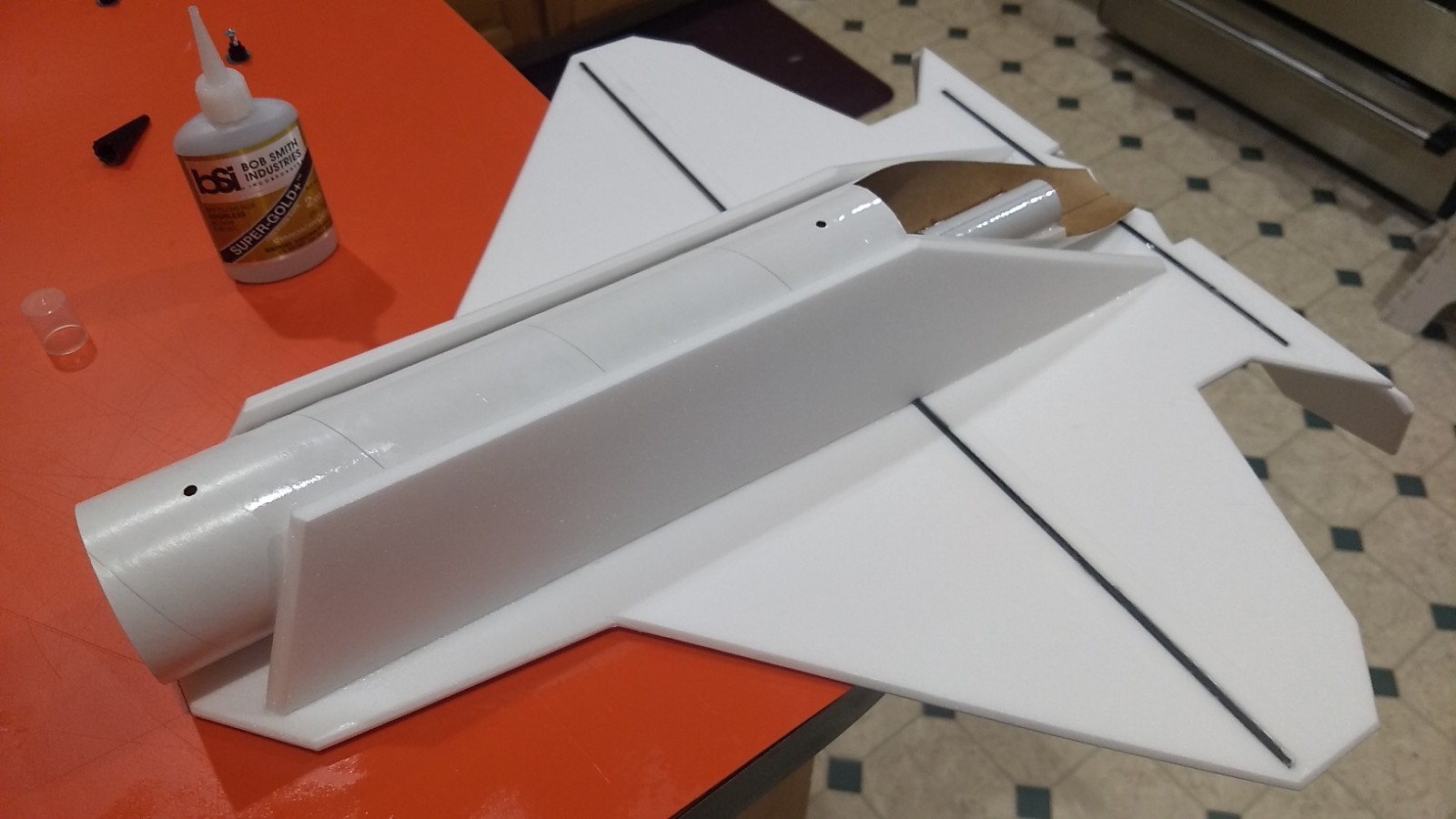
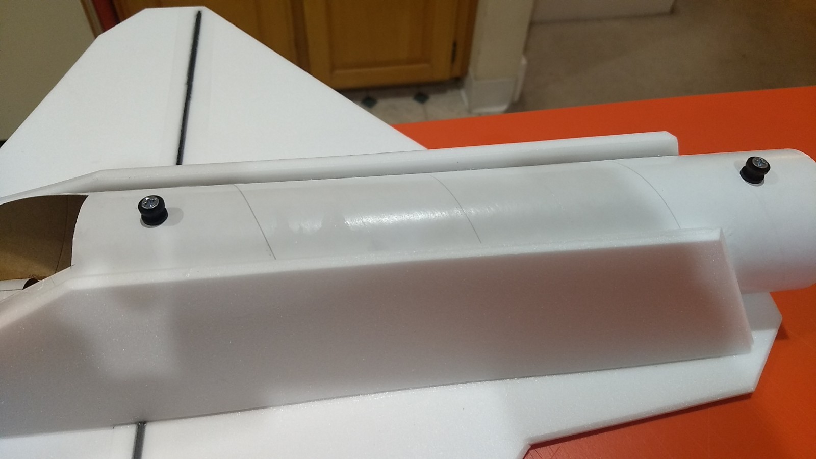
- If your kit came with a motor block ring, glue it to the front of the motor tube at this time. Glue the motor tube onto the inside top of the body tube on the line marked, the rear end of the tube will be about 1.75″ from the rear of the tube. Once set, glue a foam reinforcing strip on either side of the motor tube. I recommend that you can apply a coating of CA to the body tube to the rear of the motor tube to make sure it is protected. See picture for clarification.
- Insert one of the intake/vertical stab pieces into the slot in the wing, they are marked left and right and the gluing surfaces are pre-cut at an angle. Glue the intake plate to the wing making sure it stays flat. Then glue the intake to the side of the body tube, it may take some squeezing of the intake plate to touch the wing, take your time and make sure it is glued well. Flip the model over and glue the stabilizer on both sides of the slot. Repeat for the other side.
- Install the two rail buttons in their respective holes.
- Glue the 4 cockpit pieces together.
- At this point shape the cockpit as per the pictures. When done lay it against the front of the wing and see how it fits. Wrap some 220 grit sandpaper around the nose cone and gently sand the bottom of the cockpit so it will sit flush on the cone. You may need to trim the rear so it sits flush on the wing when the cockpit is installed. When happy, glue the cockpit in place making sure not to glue the nose cone to the body tube!!! You may need to press and hold the front and rear of the cockpit till they set. Apply a fillet of glue once set to help fill in any gaps.
- Once dry, cut the cockpit through at the nose cone joint so that they can separate.
- Glue each control horn in place on the bottom of the control surface using the pre made holes. If your model does not have the pre made holes, you can make them with a round toothpick, the horn should glue in to the bottom of the surface 1″ out toward the wingtip from the inboard end of the hinged surface. The control horn holes should be pointing toward the front of the model. Repeat on the other side.
- Put some CA on the top of the control surface where the horn prongs stick through, this locks it in place
The basic construction is now complete.
Radio Installation
Note: Your radio needs to be configured for Delta mixing, this means that the servo arms will move the same direction during elevator stick movement and opposite for aileron stick movement. Connect your servos to the receiver one in the aileron connection and one on the elevator connection and apply power. Use a servo arm at least 9/16” long and with holes small enough that there won’t be slop with the pushrod wire when installed. I use the hole furthest out on the servo arm, to maximize movement. On some servos there are a long two-ended servo arm, you can trim off one end if needed to get sufficient length. Zero out any trim settings on the transmitter.
- Connect a servo to each pushrod. If the pushrod is too tight, you can use twist an exacto knife in the servo arm hole to make it larger, but be careful and do not make it too large. Once connected, tape each servo in place so that the control surfaces are centered. Flip the model right side up and look at it from the rear. Moving the transmitter stick back(up elevator) should move both elevons up. Moving the transmitter stick to the right should move the right elevon up and the left elevon down. If you can’t get the servo reversing to give you the right polarity try swapping aileron/elevator inputs to the receiver or turning the servos over and swapping the servo arms to the other side of the output shaft. If that is correct, continue.
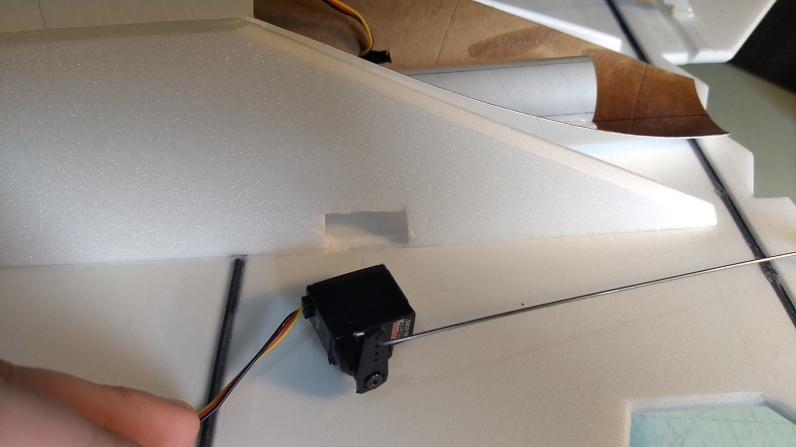
- Flip the model upside down and supported. The servos may be attached to the model using double back servo mounting tape(not included) or by directly gluing the servo to the wing with CA+ or a small amount of epoxy. Double back servo tape can loosen over time and with exposure to heat, I prefer to glue the servo in place. I marked where my servos would go then cutout the side plate to fit the servo, this allows you to recess the servo slightly. I cut a 1/8″ by 1/2″ slot from the inside of the rear of the body tube in line with the servo pocket so you can pass the servo wire through to the inside. Make sure to remove any glue from the side plate when you remove the cutout so that the servo can glue to a flat surface. Attach both servos to the receiver and power up the receiver/radio again.
- With the radio still on, put a small amount of glue on the servo, being careful not to get any near the output shaft. And slide it into the pocket in place on the model keeping the control surface centered. Do the same to the other side. Make sure the glue is set before continuing.
- Flip the model back right side up. Make sure the control surfaces are centered, use trims if needed. Now measure the control surface movement. Full elevator movement should be 1” in each direction, aileron movement should be 1″ in either direction. Since the model will be nose heavy, extra elevon movement helps to give sufficient authority during glide.
- If you have a flap/elevator mix you can program up elevator to a switch setting. The model needs approximately 3/16″ to 1/4” of up elevon during glide. If you can’t set the up elevator trim to a switch on your radio you’ll have to manually put in boost and glide trim which is hard to do while flying the model. My model needed about 1/8″ of downtrim for straight boost.
- Attach a servo extension to the battery wire and connect it to the receiver.
- Attach the receiver into rear of the body tube with provided velcro.
- Attach the flight battery into the nose cone with the rest of the provided velcro.
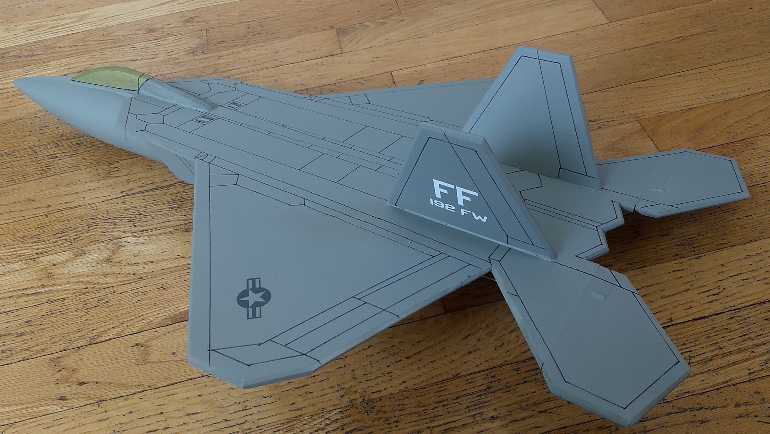
- Finish the model as desired, see general instructions for paint recommendations and warnings. I painted mine with testors spray dark flat aircraft gray. I used a sharpie pen and clear drawing triangles to make panel lines using the 3-view as a rough guide and it adds a lot to the model and doesn’t take that long. I used a Bic permanent gold marker to make the gold cockpit, you could use gold enamel or acrylic paint.
- If you use the stickershock vinyl, read the general instructions on applying them and use a warm hair dryer to soften them after applying and press them down into the painted surface gently to set them.
- Balance the model after you have painted it as this will add tail weight!
- Insert your heaviest loaded rocket motor into the motor mount and install the flight battery as if you were going to fly it.
- Support the model right side up at the balance point indicated for boost. Glue pieces of the included lead weight in the nose or tail as needed to balance it. Do not try to fly the model with it balancing it behind this point or significantly nose heavy. The adage is, a nose heavy model flies poorly, a tail heavy model flies once.
Flying: See the General Information link at the top for flying instructions. Be ready on the first few flights to keep the model straight till you have the trims set perfectly for boost and glide.
-
- glue the taped joint on the wing then lay flat to dry
-
- Glue the body tube to the wing even with the front of the wing
-
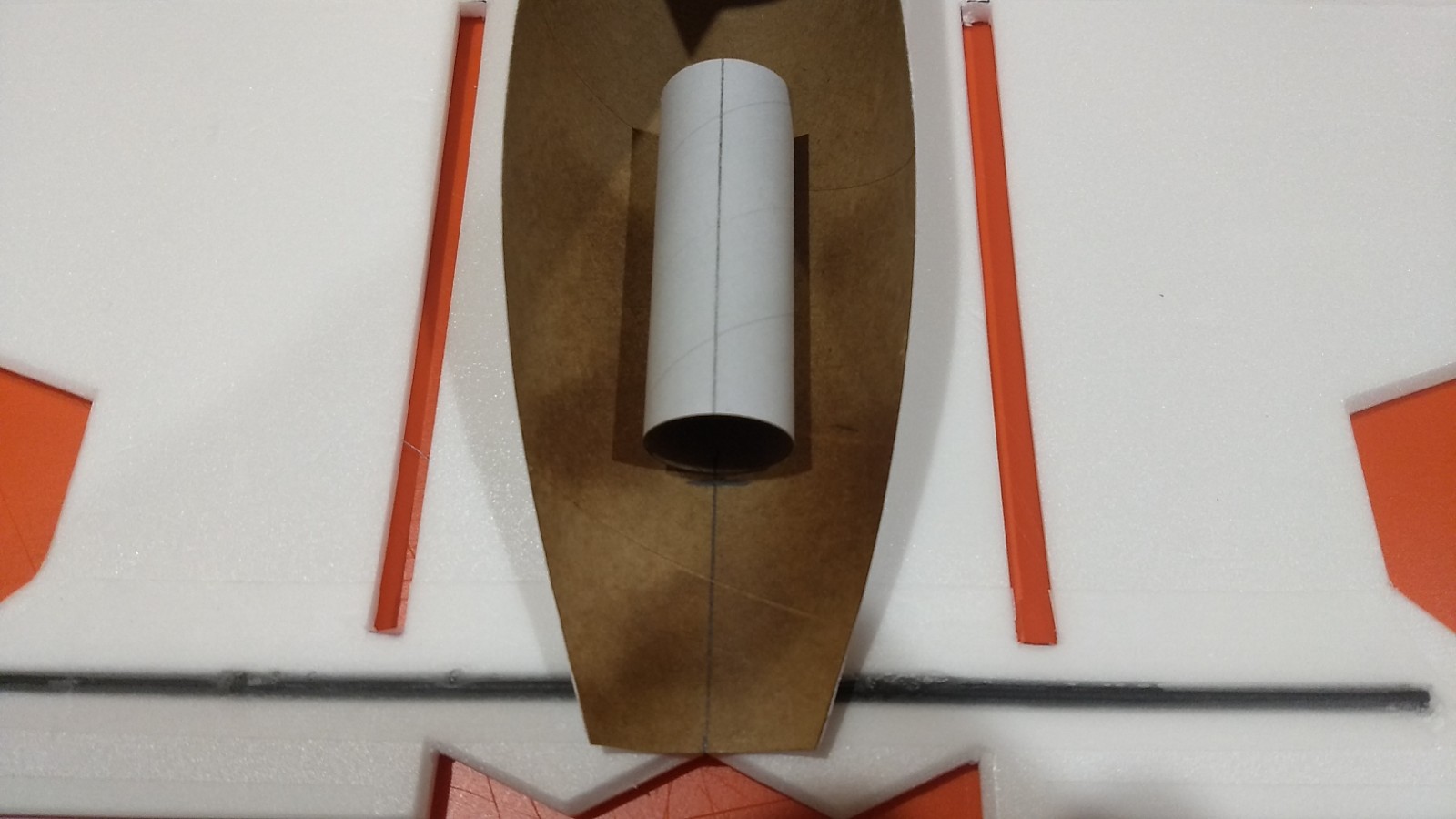
- Glue the motor tube inside the rear of the body tube on the line marked, it should be inset 1.75″ from the rear of the body tube as marked.
-
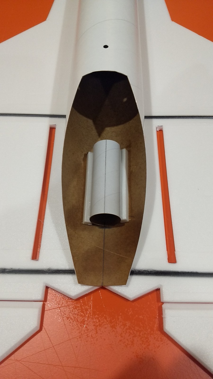
- add angle cut reinforcing strips on both sides of the motor tube and add a fillet.
-

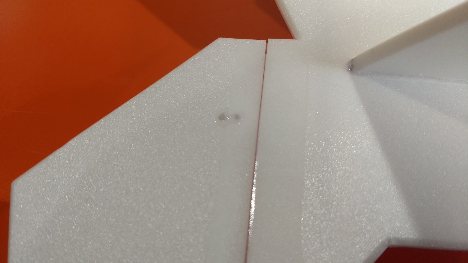
- Insert an intake plate/vertical stab against the model and glue in place.
-
- repeat on the other side.
-
- add the rail buttons on the front and back.

-
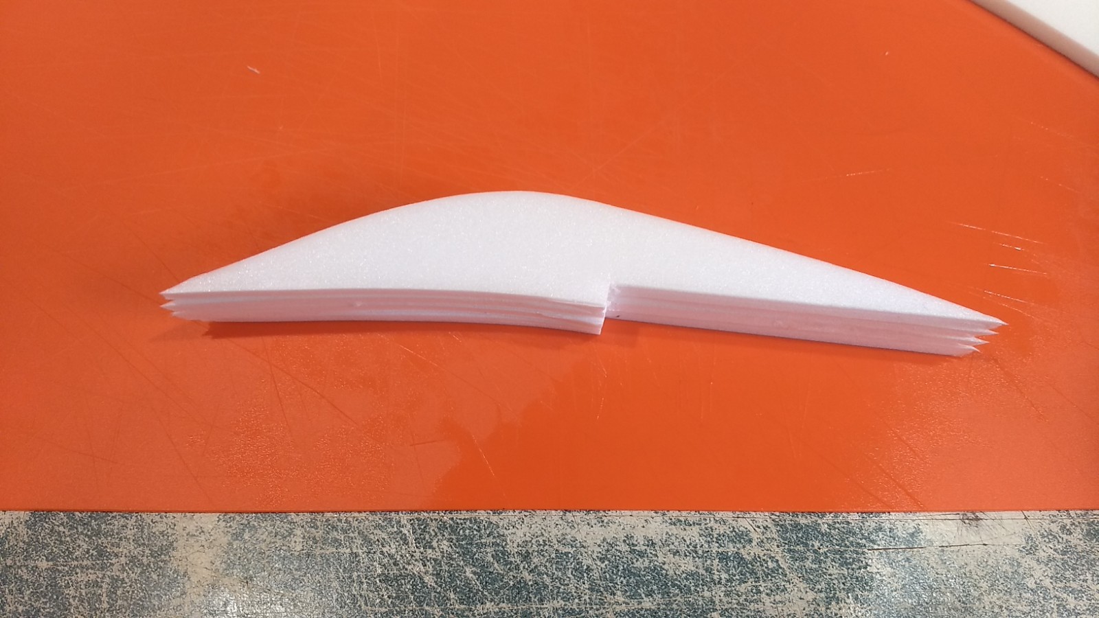
- glue the cockpit pieces together.
-
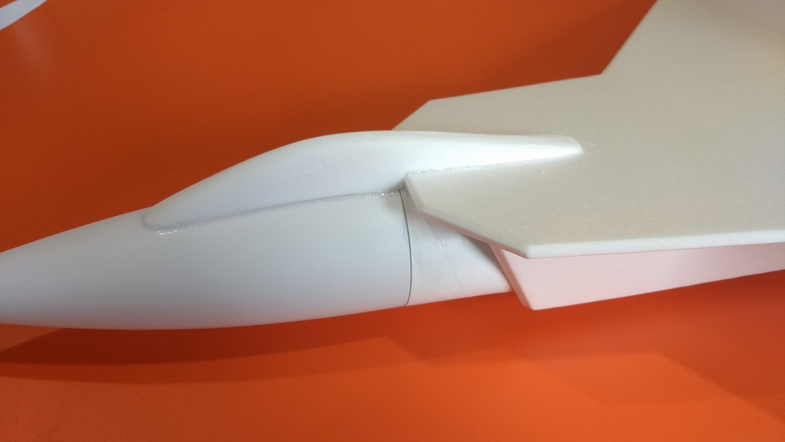
- shape the cockpit, sand the bottom to match the nose cone profile, fit the rear then glue in place.
-
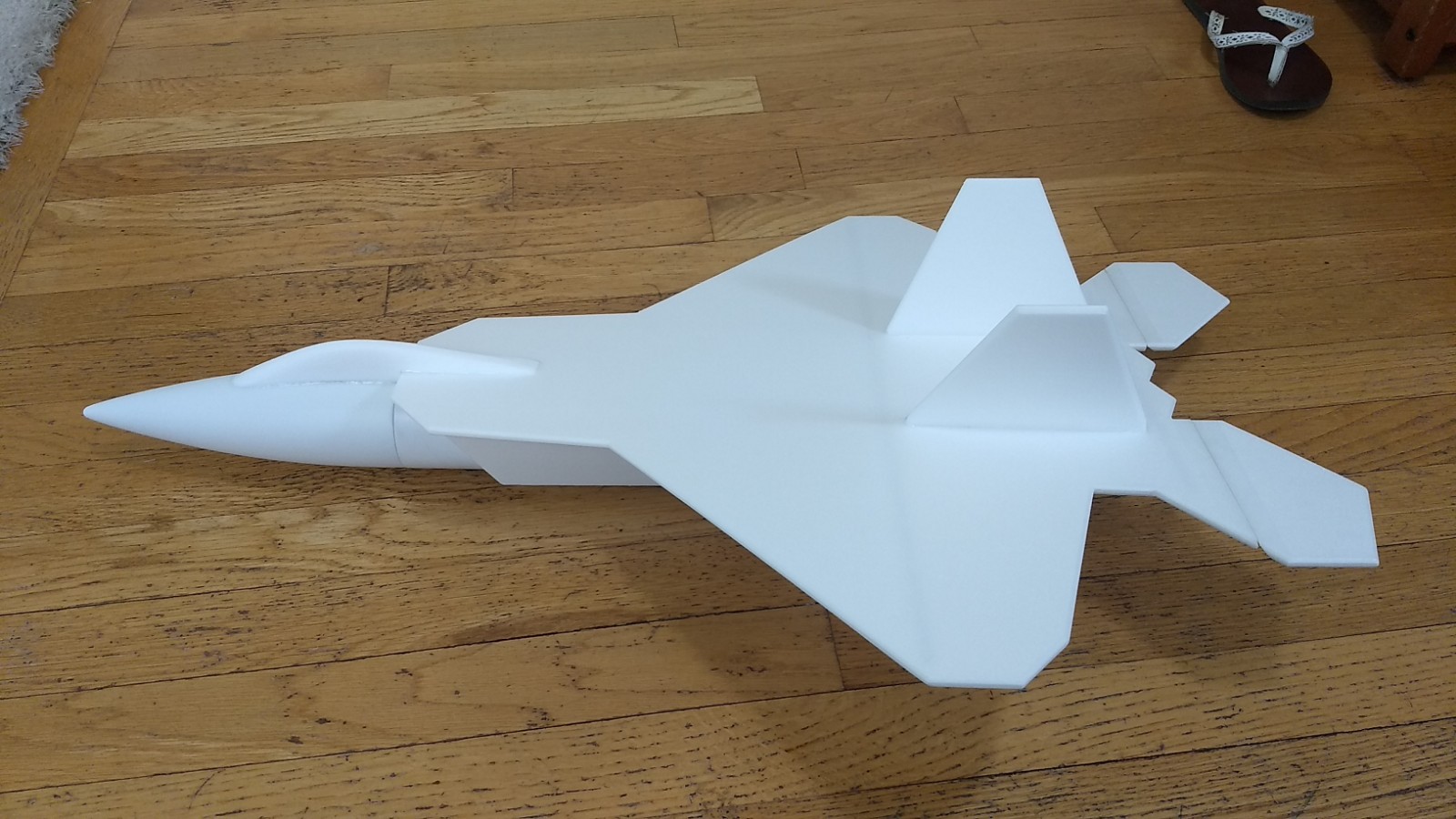
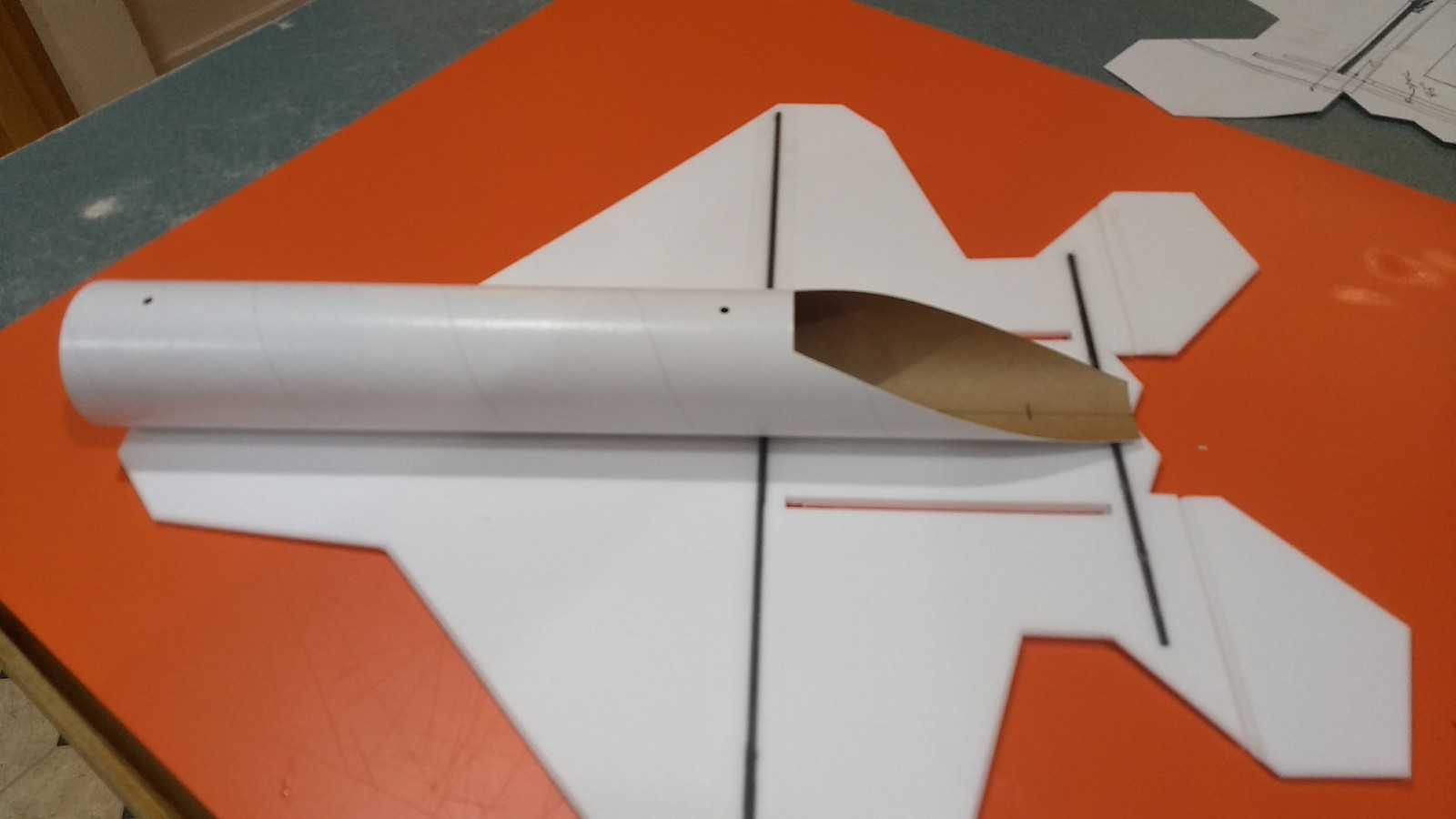
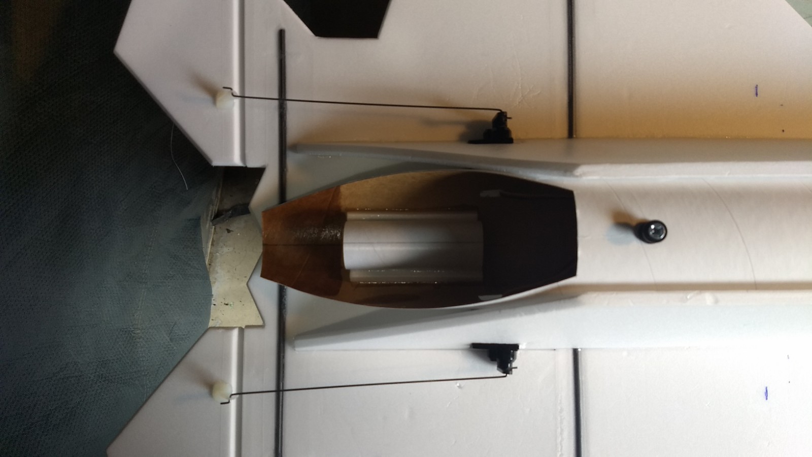
- Completed airframe.
-
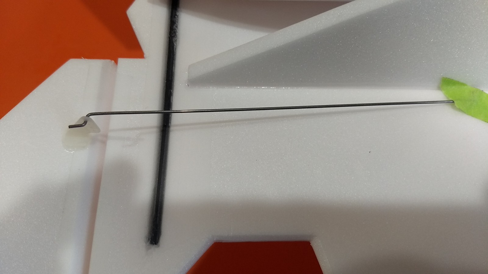
- Glue in pushrod/horn into each control surface on the bottom. Note the pushrod is closest to the body tube! Repeat on the other side.
-
- Put a fillet of glue on the top of the control horn prongs to lock them in place.
-
- Cut pocket for servo.
-
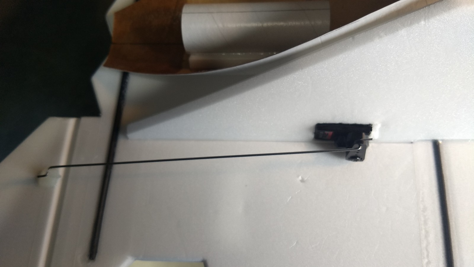
- Install servo into pocket and glue in place with control surface level.
-
- Servos installed.
-
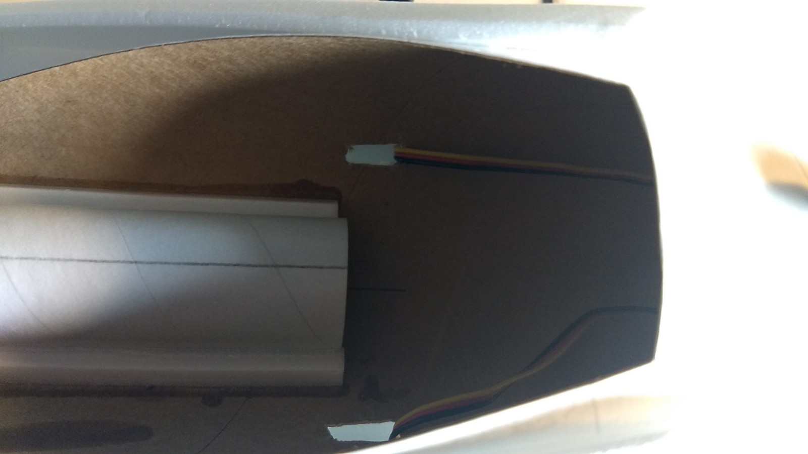
- Cut holes for the servo wires and route into the body tube and connect to the receiver.
-
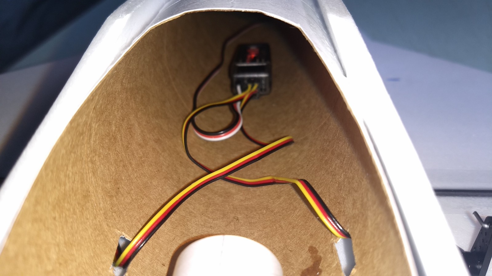
- locate the receiver in the rear of the inside of the body tube using velcro.
-
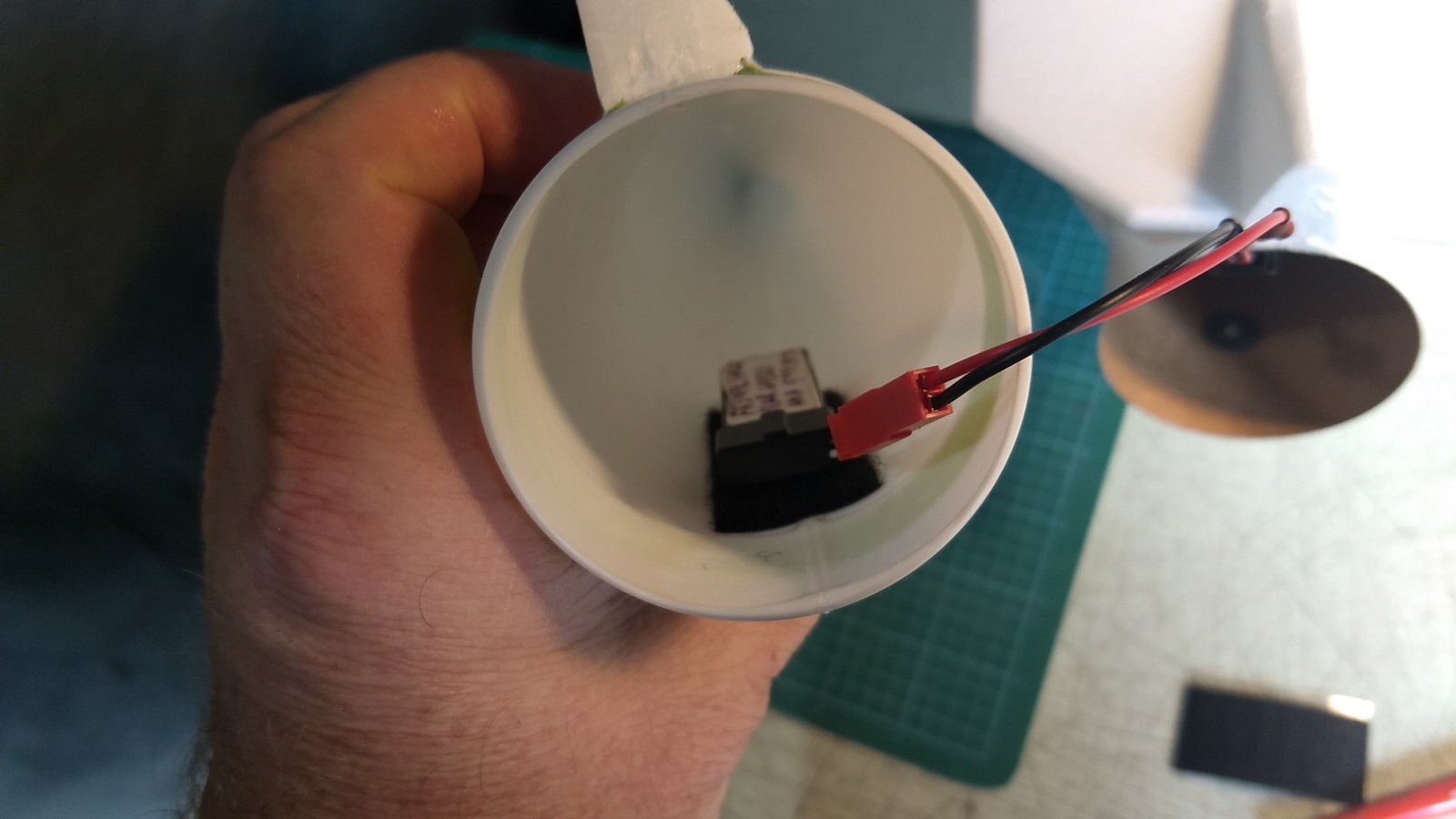
- Connect the battery inside the nose cone using velcro.
-
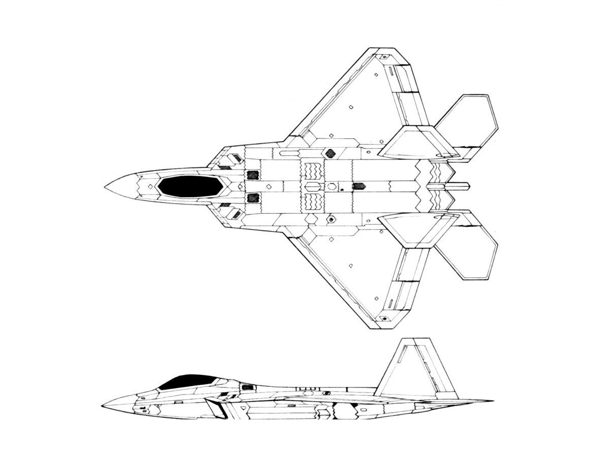
- Line drawing for panel line ideas
-
- Completed model