The Avro Arrow RC Rocket glider kit is based on the world beating interceptor developed in Canada. It features a high mounted delta wing with spar pre-installed, a plastic nose cone, 2″ white tubing for the body and depron wing and tail surfaces. Wing elevons are pre-hinged. The body tube end is pre-cut at an angle and the rail buttons are pre-installed. You will need two 10 gram type servos, a receiver, and a small 500mah single cell lipo battery. You will need a transmitter with delta or elevon mixing. Specs: 34″ length, 23.5″ wingspan, 10.5 oz rtf, for 24mm E-6 single use or reloadable motors.
High quality vinyl decals are available HERE:
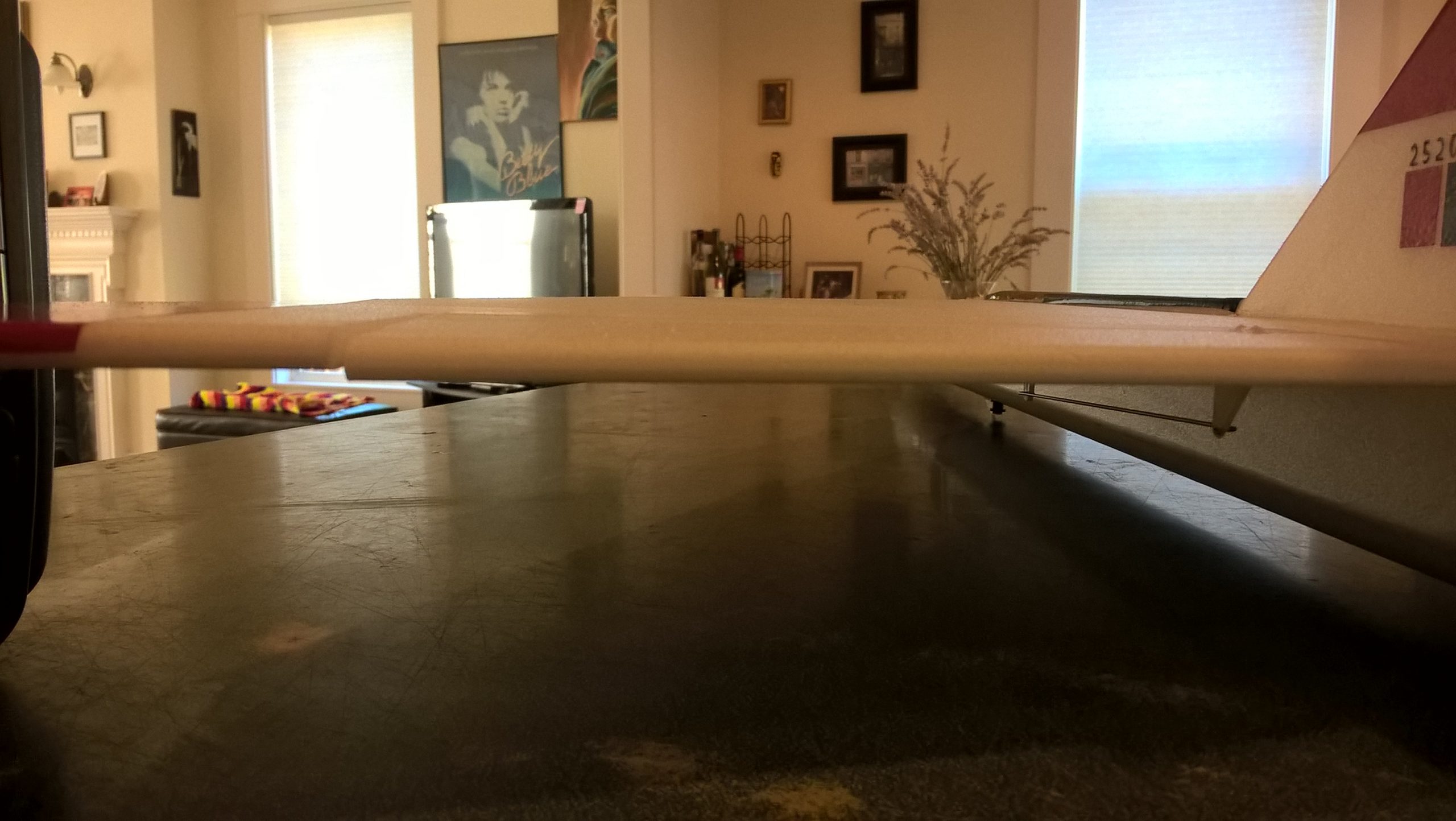
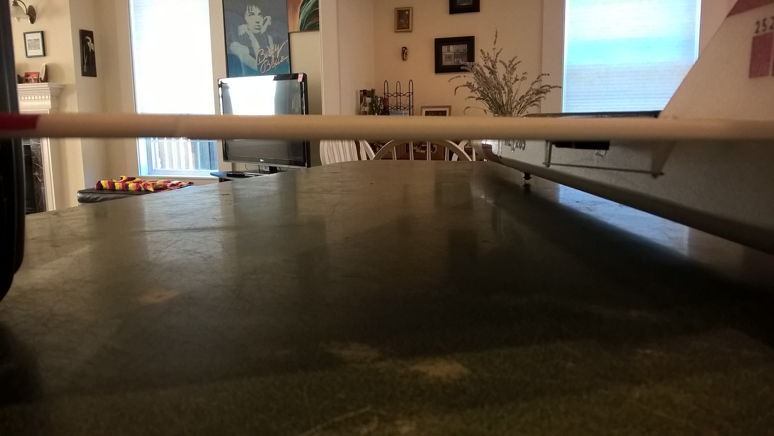
CG location for rocket flight with battery and loaded motor installed: 1/2″ to the rear of the notch in the leading edge of the wing.
Please refer to the General Information Link above then read the instructions completely before starting assembly. The assembly photos are for general reference but may not include every step in the instructions. If you want hardcopy to work from, all you have to do is click/drag/select and copy all of the text below, open word and paste with “keep original format” and it looks exactly like it does online then you can print it.
Unpacking your kit:
The kits are packed to protect them in shipping, but the contents are fragile so unpack carefully. Carefully cut the tape holding the tubes in the box, then unwrap/lightly cut the plastic wrap to free the tubes, the spar may be packed in the tubes and the baggie with the little parts and nose cone will be in the tubes as well. Carefully cut the tape holding the cardboard wing protector in the box and carefully remove it, don’t pull hard or bend it. Then carefully cut the tape holding the cardboard top piece to the bottom. There may be some sticky tape holding the cardboard to the bottom cardboard piece, carefully peel it being sure not to bend anything. Once the top cardboard is free you can see the foam wing/tail parts, there are little fragile pieces in here, so unwrap carefully. It may be best to use an exacto to lightly cut the plastic wrap and carefully remove it without cutting into the foam. Make sure everything is free before you remove the pieces to avoid breaking anything. Kits contain one or two scrap pieces for repairs if you damage anything in construction or flight, just cut and patch in a spare piece of the foam if needed using foam safe CA+.
Welcome to the world of rocket boosted radio control gliders. This is not a model for a novice RC pilot, but anyone who is comfortable with RC flying of a medium speed model should be fine. Read through the instructions, look at the photos and be sure you understand the step before commiting to cutting or glue.
Avro Arrow Rocket glider instructions
Identify all pieces, the kit should contain:
1 wing taped together
1 Nose Cone
1 coupler
1 vertical stabilizer
2 control horns w/pushrods
2 2.75″ beveled motor tube supports
2 Body Tubes
Motor mount
2 engine intake plates.
1 long 9/16″ wide conduit/cockpit
1 short 9/16″ wide lower conduit/cockpit strip.
Velcro(for battery and rx/bec attachment)
Lead weight
Spare depron
Notes before starting:
Reference to glue, CA, or CA+ means foam safe CA+, normal CA+ will melt the foam! Normally you need to use accelerator to get the CA to set on the foam since there is nothing for it to soak into and activate.
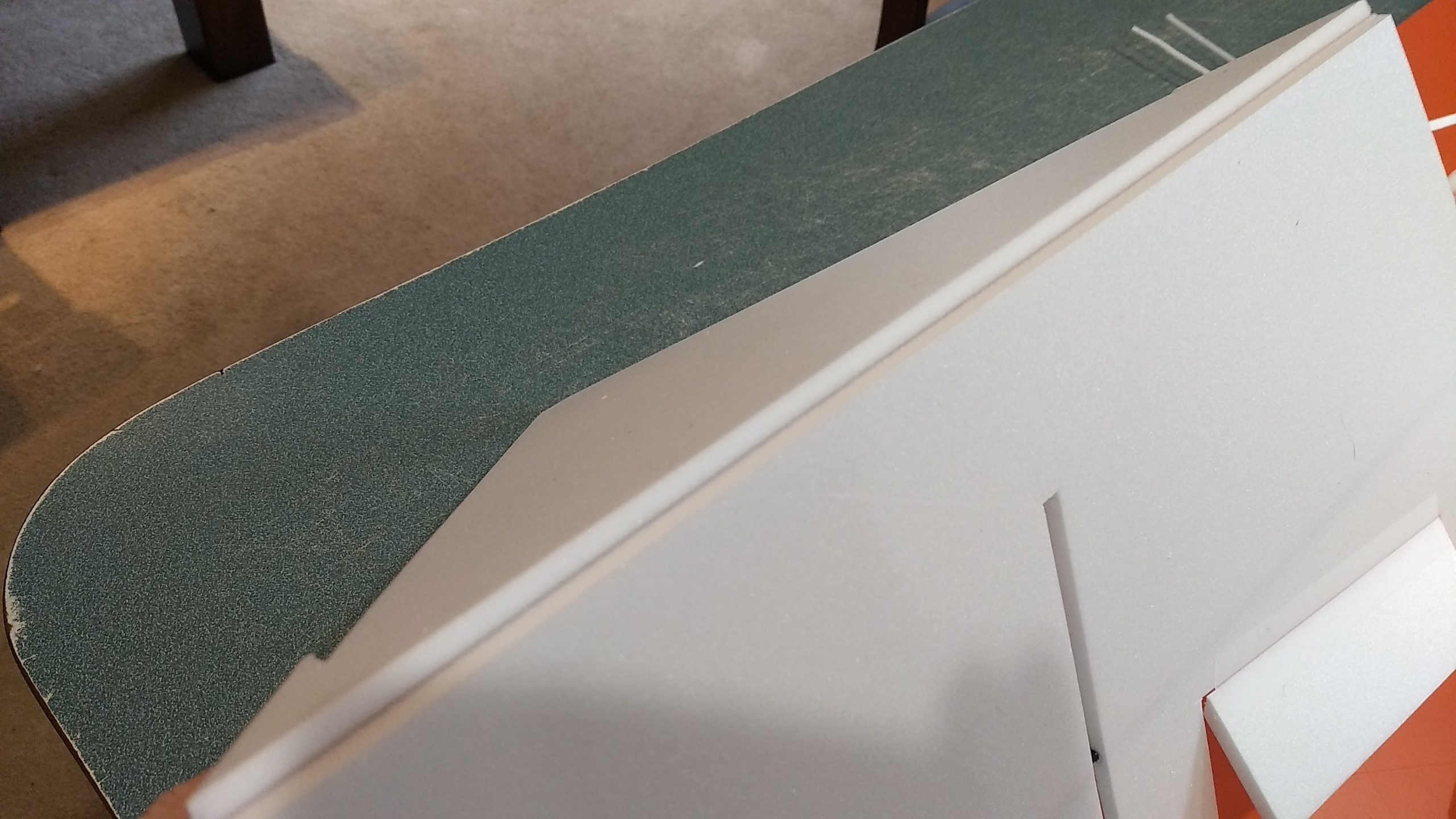
You may use 320 grit sandpaper and a sanding block to slightly round the edges of the foam if you prefer that look. It will not markedly impact the flight performance either way. Be very careful and use a VERY light touch, it is very easy to catch the foam on the edge of the paper and tear the foam. Do any sanding before assembly.
Epoxy is not needed in this model. Weight is critical and the model is designed for the thrust and flight loads.
Assembly:
- Body Tubes. Join the two tubes using the provided coupler. Make sure the small arrow marks are aligned on the two tubes, that will ensure the wing marks are properly aligned. On some kits this coupler may have been pre-glued in one half.
- Unfold the wing and apply glue to the wing at the taped joint and set it on a flat surface to dry face up. Then flip the wing over, the bottom of the wing will have the spar visible.
- Lightly sand the fuselage wing line and apply a squiggle of glue about 1/2 wide to the body tube wing line, the bottom of the center of the wing.
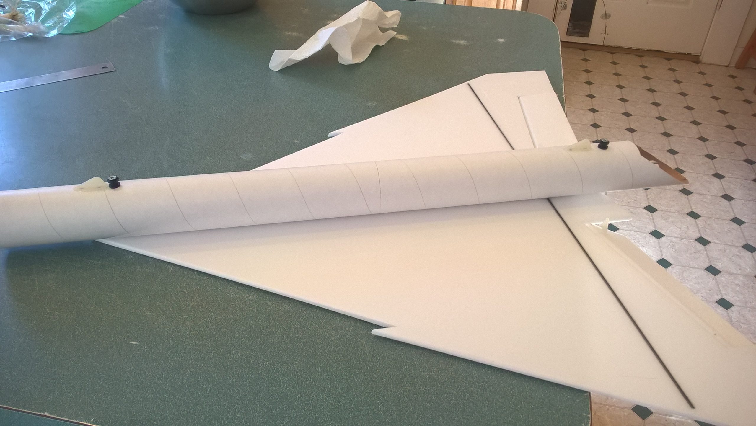
- Lay the wing on the body tube on the alignment mark using the rear center of the wing and the rear line on the alignment line as a guide. Flip the wing and body over onto a table top, making sure the wing does not move and make sure the body tube is centered. You can measure from the wingtip to the body tube side on each side to make sure it is centered. Make sure it is set before continuing.
- Glue a motor intake to each side of the body tube and onto the wing. The notch will hit against the front of the wing and the front of the intakes will be near or slightly ahead of the front of the body tube. Apply a fillet of glue along the wing and intake to make sure you have a good joint on the rest of the piece.
- If your kit came with a motor block ring, glue it to the front of the motor tube at this time. This is not needed if you have a motor hook. Glue the motor tube onto the inside top of the body tube on the line marked, the rear end of the tube will be about 1.75″ from the rear of the tube and the motor hook will be pointing up. Once set, glue a foam reinforcing strip on either side of the motor tube. On my model I saw no burning of the rear of the tube, but you can apply a coating of CA to the body tube to the rear of the motor tube to make sure it is protected. See picture for clarification.
- Test fit the vertical tail into the slot and make sure it fits. Make sure the tail is straight with no warps, bend carefully by hand to straighten it if needed. Glue into the slot using foam safe CA+ making sure the tail is perpendicular to the wing and is straight.
- Glue the short conduit/cockpit to the bottom of the long conduit so that the pointed ends line up. The short piece you glued in place will be the bottom of the assembly.
- At this point shape the cockpit as per the drawing on the included template guide or refer to the picture, then round the top of the long conduit piece. When done lay it against the front of the wing and trim the rear at an angle to fit cleanly against the front of the vertical stab. Tape the nose cone in place, then glue the conduit into the top of the wing and the top of the nose cone, make sure not to glue the nose cone to the body tube.
- Once dry, cut the conduit clear through at the nose cone joint so that they can separate.
- Glue each control horn in place on the bottom of the control surface using the pre made holes. If your model does not have the pre made holes, you can make them with a round toothpick, the horn should glue in to the bottom of the surface 1″ out toward the wingtip from the inboard end of the hinged surface. The control horn holes should be pointing toward the front of the model. Repeat on the other side.
- Put some CA on the top of the control surface where the horn prongs stick through, this locks it in place
The basic construction is now complete.
Radio Installation
Note: Your radio needs to be configured for Delta mixing, this means that the servo arms will move the same direction during elevator stick movement and opposite for aileron stick movement. Connect your servos to the receiver one in the aileron connection and one on the elevator connection and apply power. Use a servo arm at least 9/16” long and with holes small enough that there won’t be slop with the pushrod wire when installed. I use the hole furthest out on the servo arm, to maximize movement. On some servos there are a long two-ended servo arm, you can trim off one end if needed to get sufficient length. Zero out any trim settings on the transmitter.
- Connect a servo to each pushrod. If the pushrod is too tight, you can use twist an exacto knife in the servo arm hole to make it larger, but be careful and do not make it too large. Once connected, tape each servo in place so that the control surfaces are centered. Flip the model right side up and look at it from the rear. Moving the transmitter stick back(up elevator) should move both elevons up. Moving the transmitter stick to the right should move the right elevon up and the left elevon down. If you can’t get the servo reversing to give you the right polarity try swapping aileron/elevator inputs to the receiver or turning the servos over and swapping the servo arms to the other side of the output shaft. If that is correct, continue.
- Flip the model upside down and supported. The servos may be attached to the model using double back servo mounting tape(not included) or by directly gluing the servo to the wing with CA+ or a small amount of epoxy. Double back servo tape can loosen over time and with exposure to heat, I prefer to glue the servo in place. With the radio still on, put a small amount of glue on the servo, being careful not to get any near the output shaft. And set it in place on the model keeping the control surface centered. Do the same to the other side. Make sure the glue is set before continuing. The servo should be near the side of the model.
- Flip the model back right side up. Make sure the control surfaces are centered, use trims if needed. Now measure the control surface movement. Full elevator movement should be 1” in each direction, aileron movement should be 1/2″ in either direction. Since the model will be nose heavy, extra elevon movement helps to give sufficient authority during glide.
- If you have a flap/elevator mix you can program up elevator to a switch setting. The model needs approximately 1/4” of up elevon during glide. If you can’t set the up elevator trim to a switch on your radio you’ll have to manually put in boost and glide trim which is hard to do while flying the model. My model needed about 1/16″ of downtrim for straight boost.
- Make a 1/8″ wide by 1/2″ long slot in the side of the model through the foam and body tube on each side near the servo and and pass the servo wires through to the inside of the model.
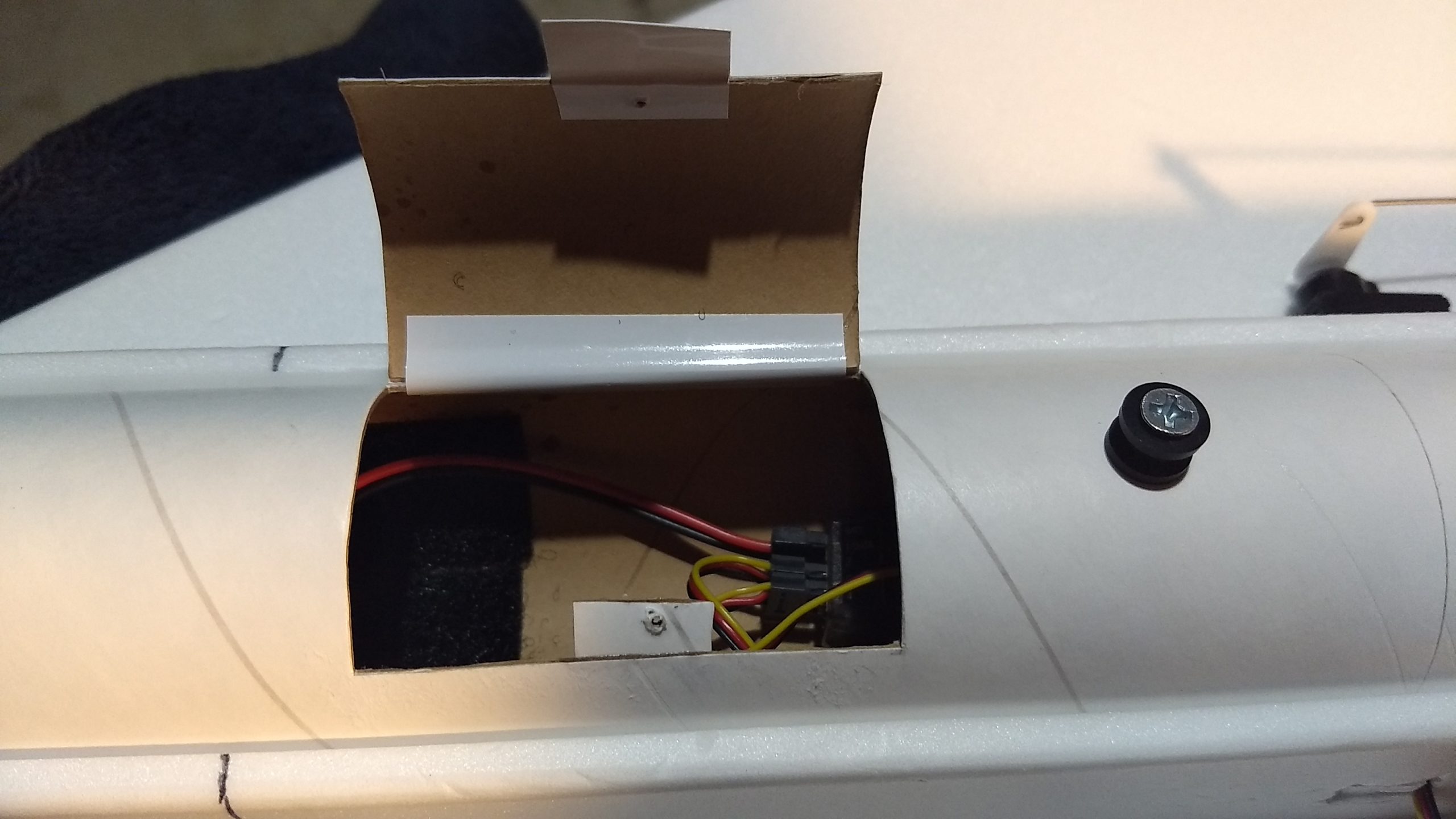
- Cut a hatch in the bottom of the body tube, this hatch should start 2.25″ ahead of the body tube joint and be about 2.5″ long and 1.5″ wide, this is for accessing the battery and receiver. I used tape to make a hinge for the hatch and I simply use a little piece of tape to hold the hatch closed for flight. You can also glue a little tab of cardboard inside the hatch and use a spare unused mounting screw from your servo package to secure the hatch. Use CA on hole once it is threaded to help it last longer. The screw method looks nice, but now you have to remember a screwdriver at the field and not lose the little screw:)(On your kit, this hatch may be partially cut through for you, simply complete the cut to remove the hatch. A small piece of cardboard and a small screw may be included as well)
- Attach the servo wires to the receiver and make sure they are going the right direction.
- Use the included Velcro to attach the receiver and flight battery inside the hatch and onto the body tube using the included velcro.
- Insert your heaviest loaded rocket motor into the motor mount
- Support the model right side up at the balance point indicated for boost. Glue pieces of the included lead weight in the nose or tail as needed to balance it. Do not try to fly the model with it balancing it behind this point or significantly nose heavy. The adage is, a nose heavy model flies poorly, a tail heavy model flies once.
Finishing:
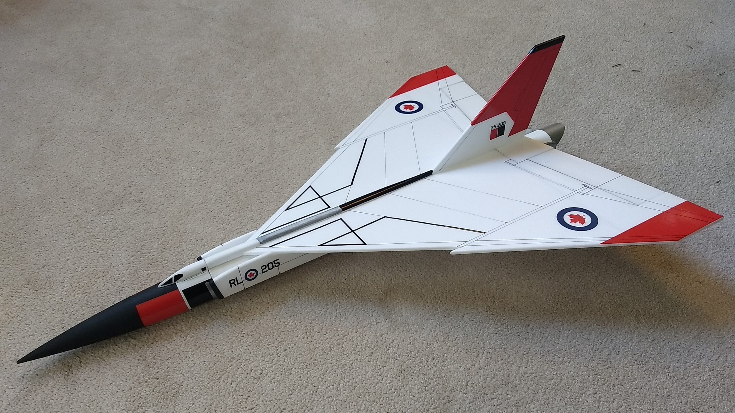
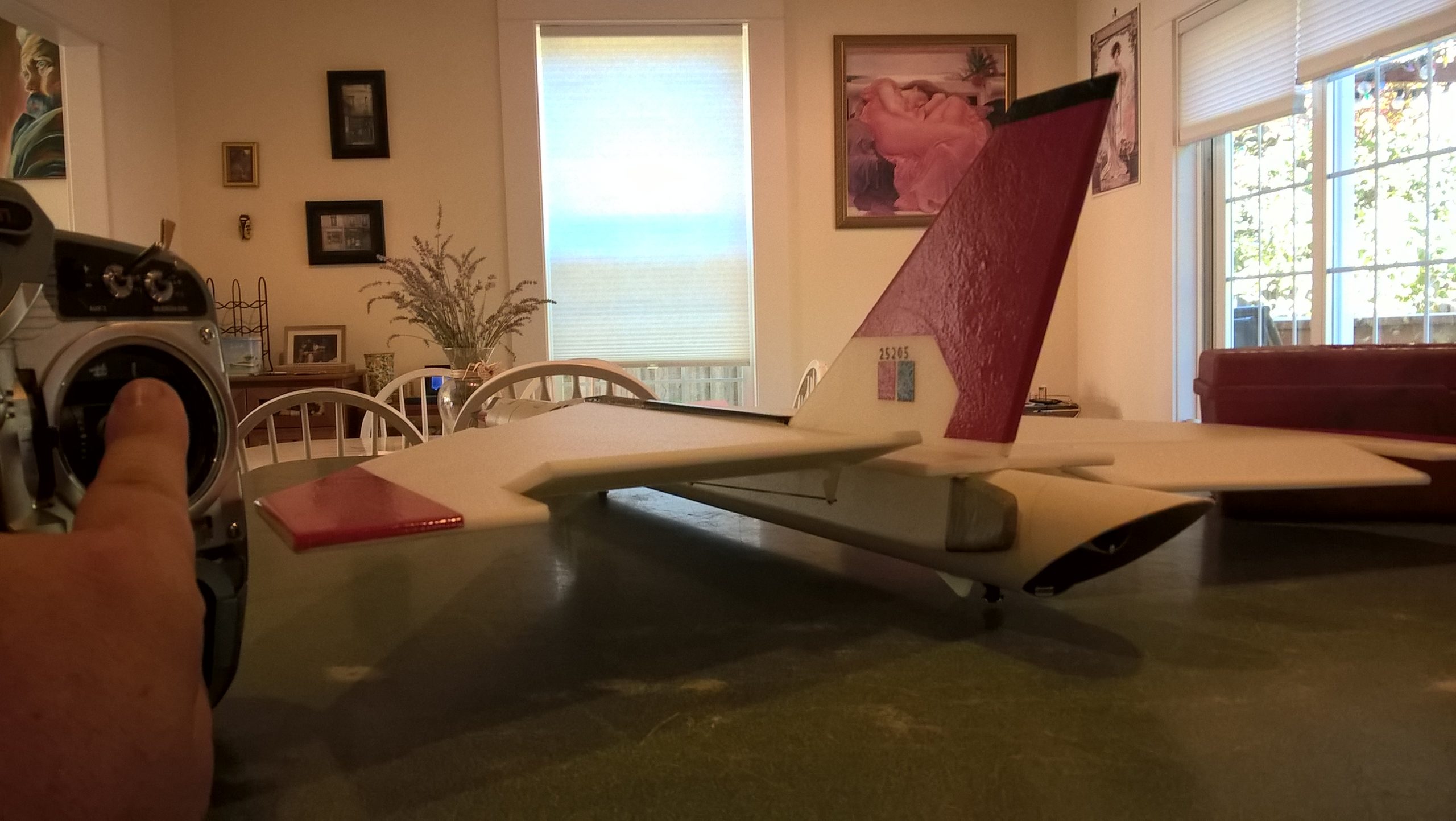
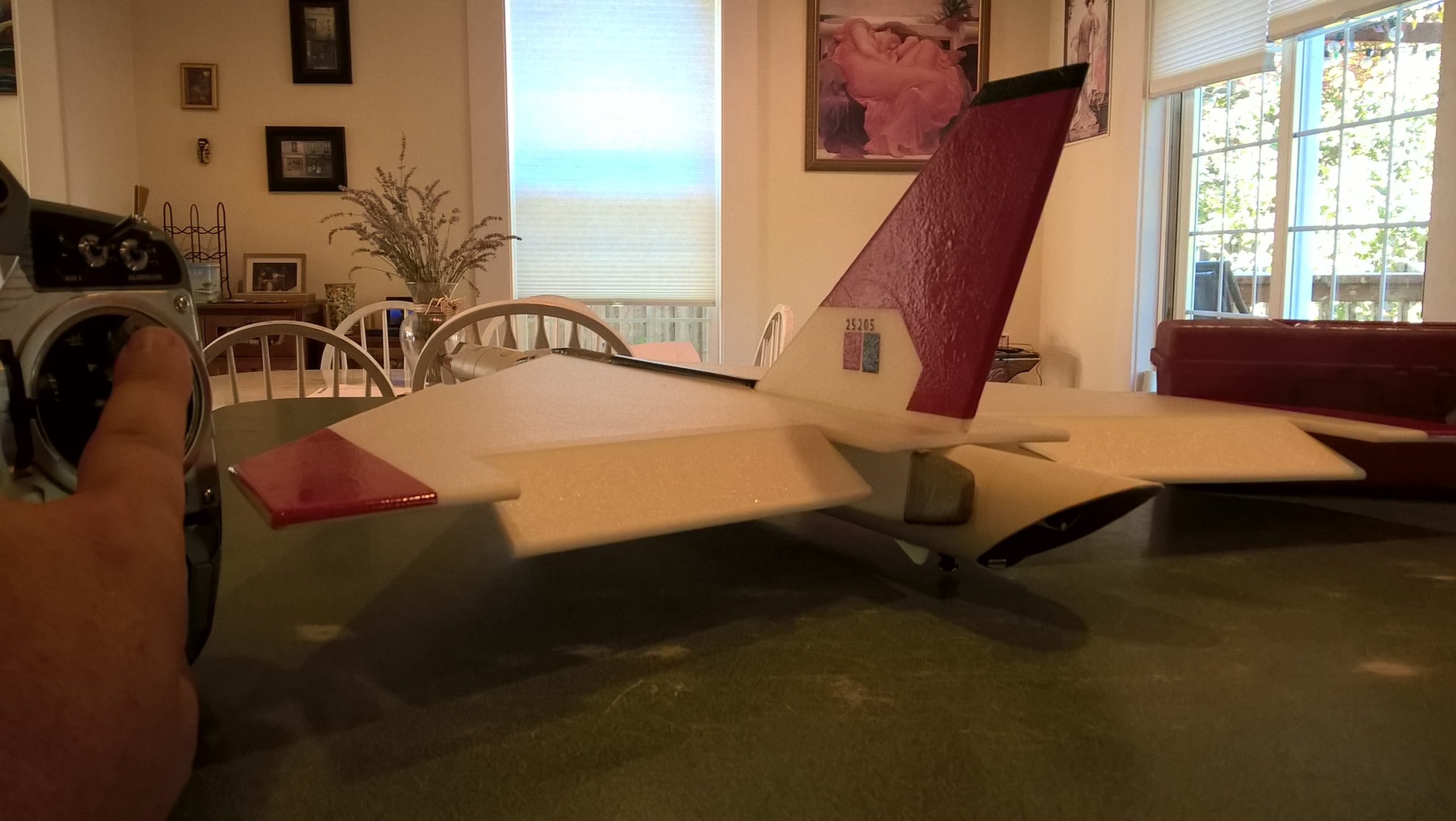
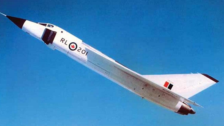
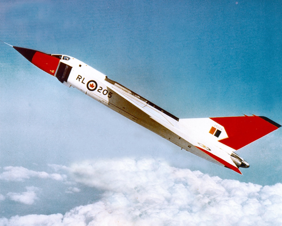
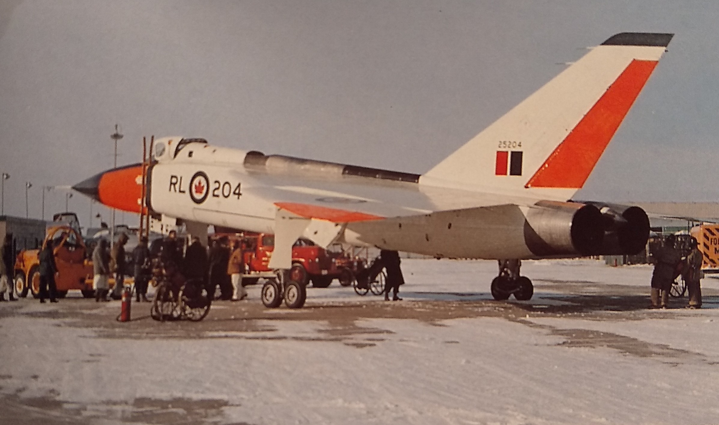
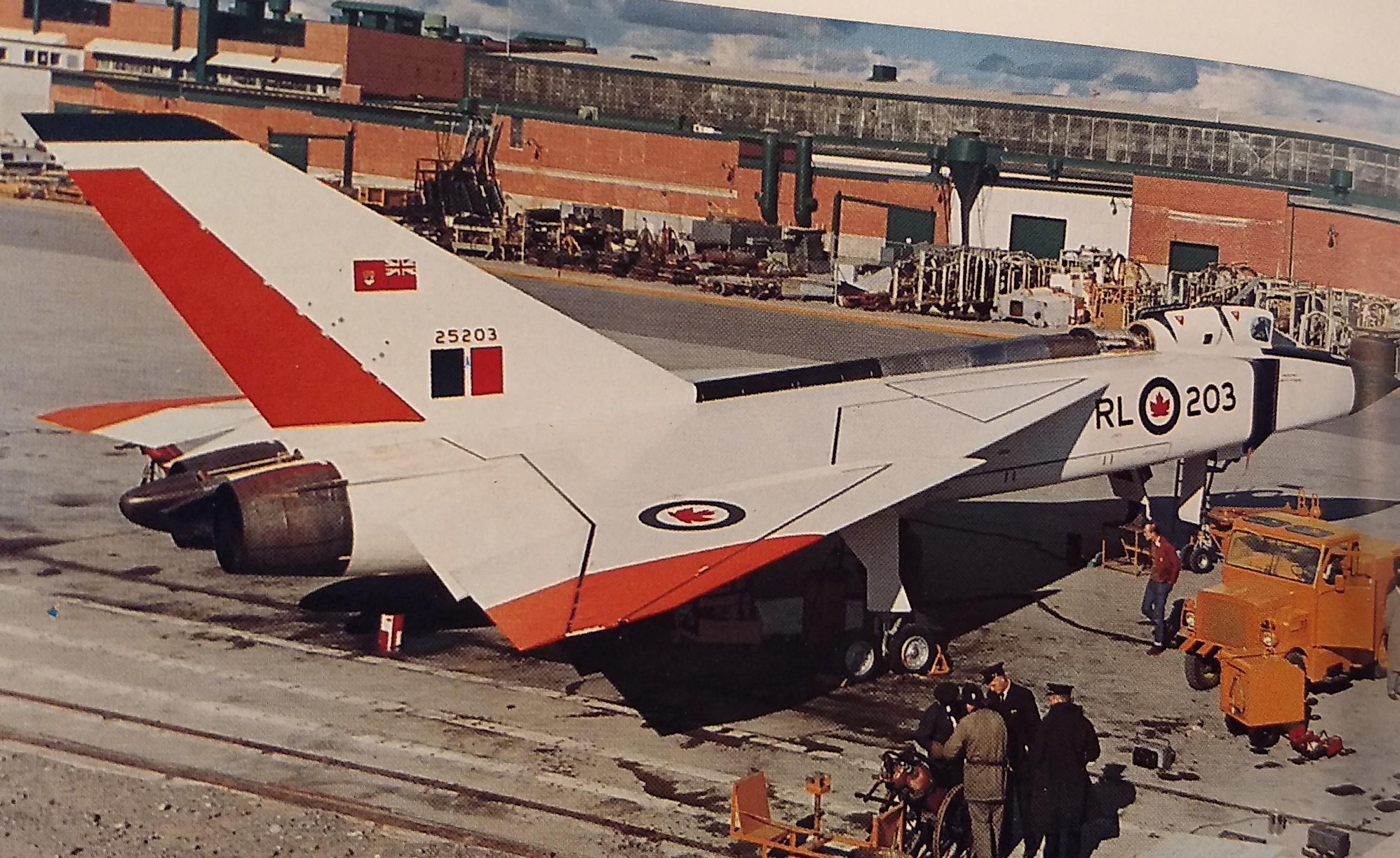
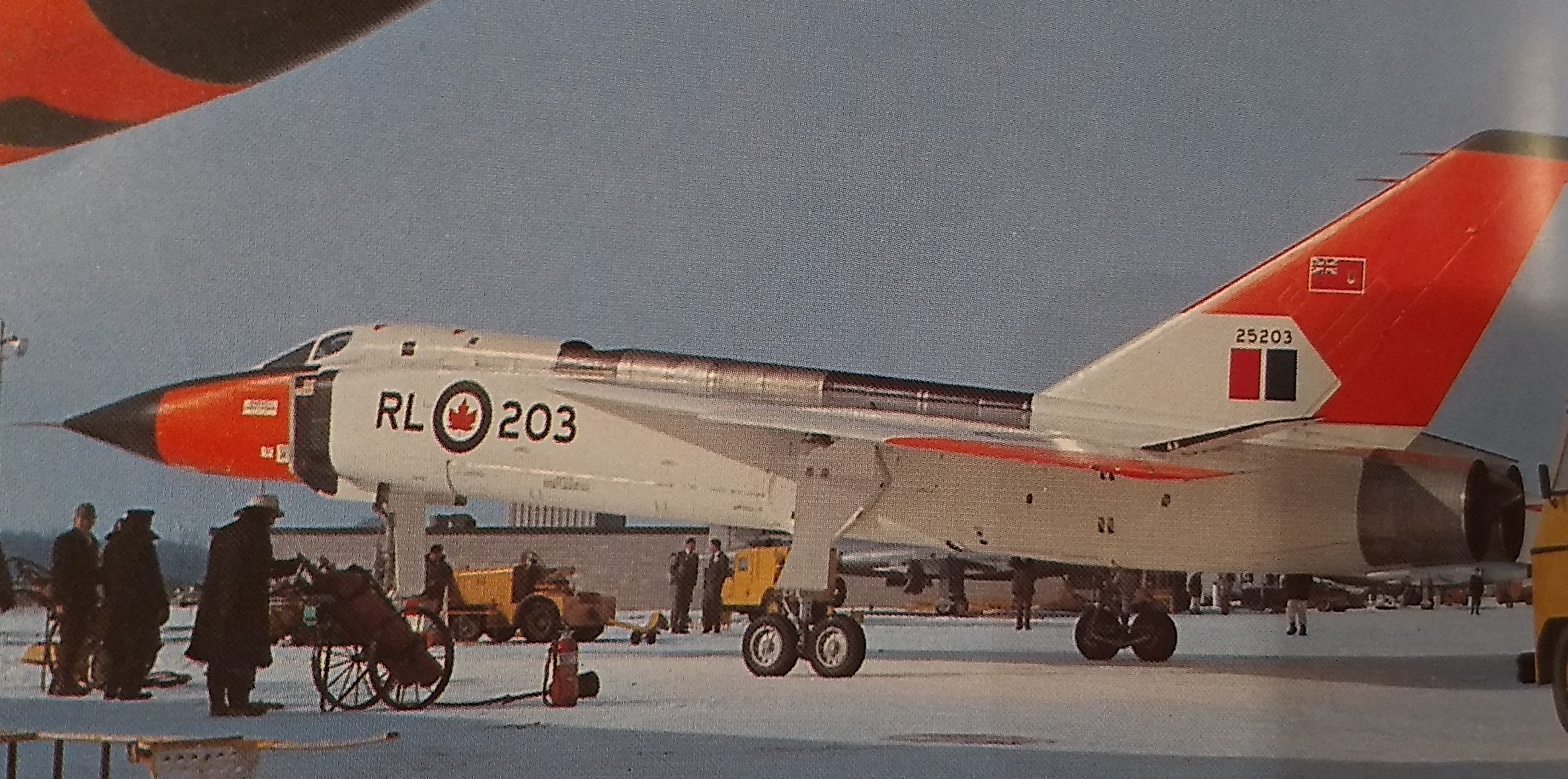
- There were several paint schemes from mostly white to multiple red areas, I chose number 205. Using the pictures below you can see differences in markings on the tails and wing walk lines, even between the same aircraft at different times in the flight program.
- Refer to the general instructions tab if you decided to paint the foam areas, I ONLY recommend testors of model master ENAMEL spray.
- Use the included templates to cut your own vinyl adhesive trim, or for painting, Or order decals HERE:
- The nose cone can be masked and painted as shown. The nose tip is black to about 1.25″ ahead of the front of the cockpit. It then continues back about 3/4″ wide and goes on either side of the cockpit to the rear of the forward cockpit window. The red section goes just below the black on either side of the cockpit extends down about 1 3/8″-1.5″. The rest of the cone and the cockpit is left white and should be masked when painting.
- The side roundels are 3/4″ tall, the wing roundels are 2″ tall. The lettering RL205 is 1/2″ tall. The small tail marking are black and red rectangles with 25205 above in 3/16″ letters in black.
- You can paint the forward portion of the intake black and the rear silver, or use the guide for cutting vinyl. The black intake splitter can be simulated with paint or vinyl forward of the intake on the white portion of the cone.
- The tail templates are cut slightly over sized to allow you to wrap around the front and rear of the stabilizer and to then trim the top even with your rudder. This allows for differences in sanding/rounding, etc. Covering the stab with vinyl also adds a lot of strength and stiffness to the stabilizer and is recommended.
- After applying the vinyl trim, use a hot hair dryer to soften the vinyl and press down with a thumb or finger to press it in place, this makes it conform and really attach to the foam.
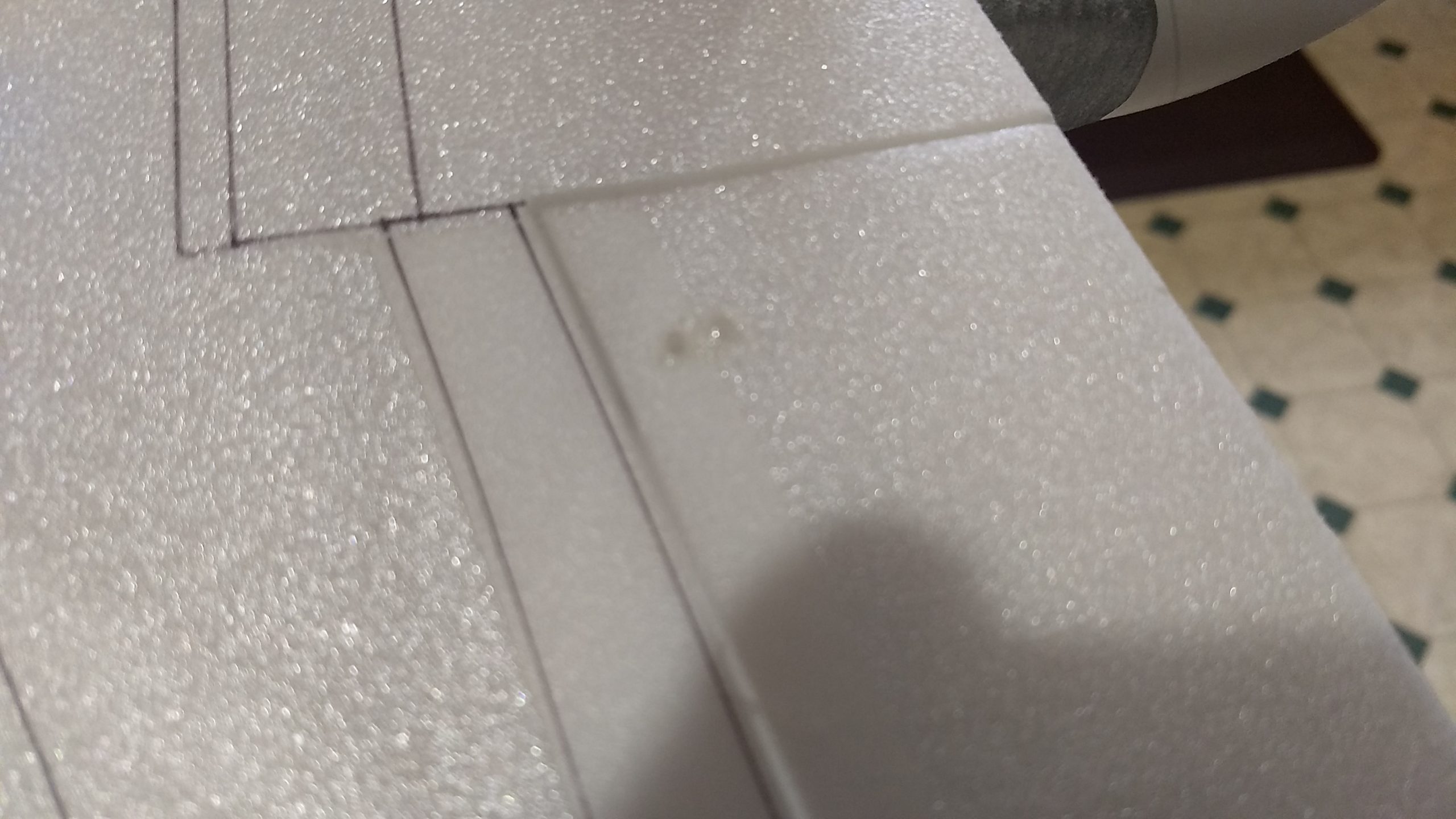
- I added a little more detail using a silver sharpie on the spine conduit and cut a little notch right at the front of the wing in the conduit. I also used a fine line sharpie pen and clear straight edge to draw some panel lines based on the drawing below. I also used some fine line pin stripe for the wing walk pattern on the top of the wing.
- Make a final verification of control movements and throws and balance before the first flight.
Flying: See the General Information link at the top for flying instructions. Be ready on the first few flights to keep the model straight till you have the trims set perfectly for boost and glide.
-
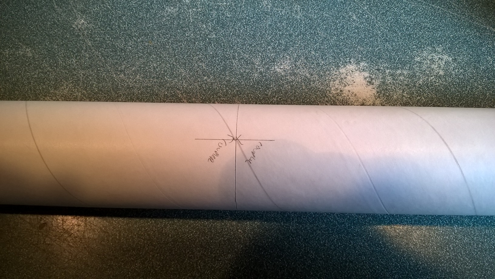
- Install the rail buttons, then Join tubes with the coupler keeping arrows aligned on the bottom wing line mark
-
- glue the taped joint on the wing then lay flat to dry
-
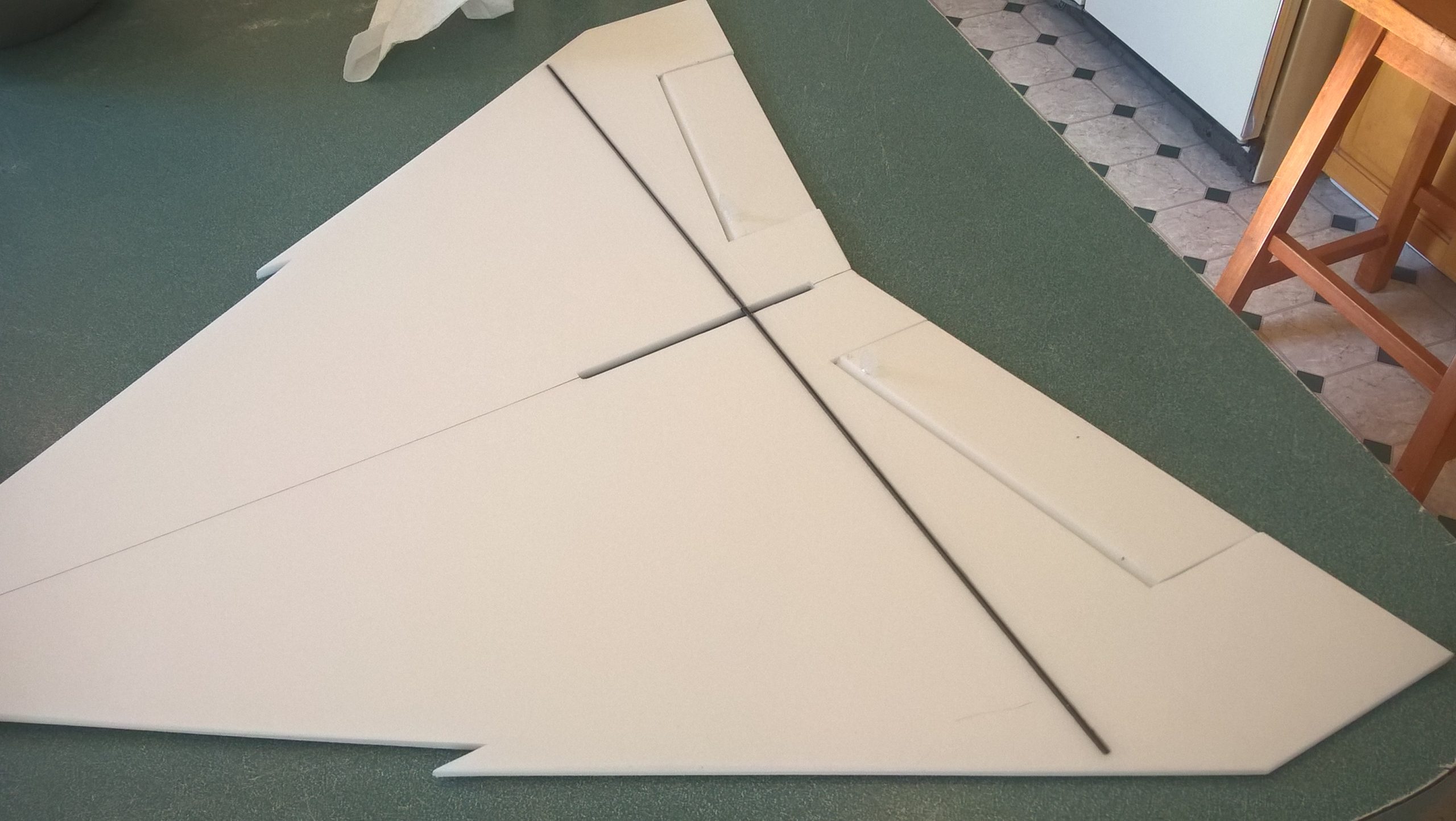
- Lay wing flat to dry then apply glue down the center of the bottom of the wing(the part where the spar is visible)
-
- Glue the wing to the body tube and place upside down to cure
-
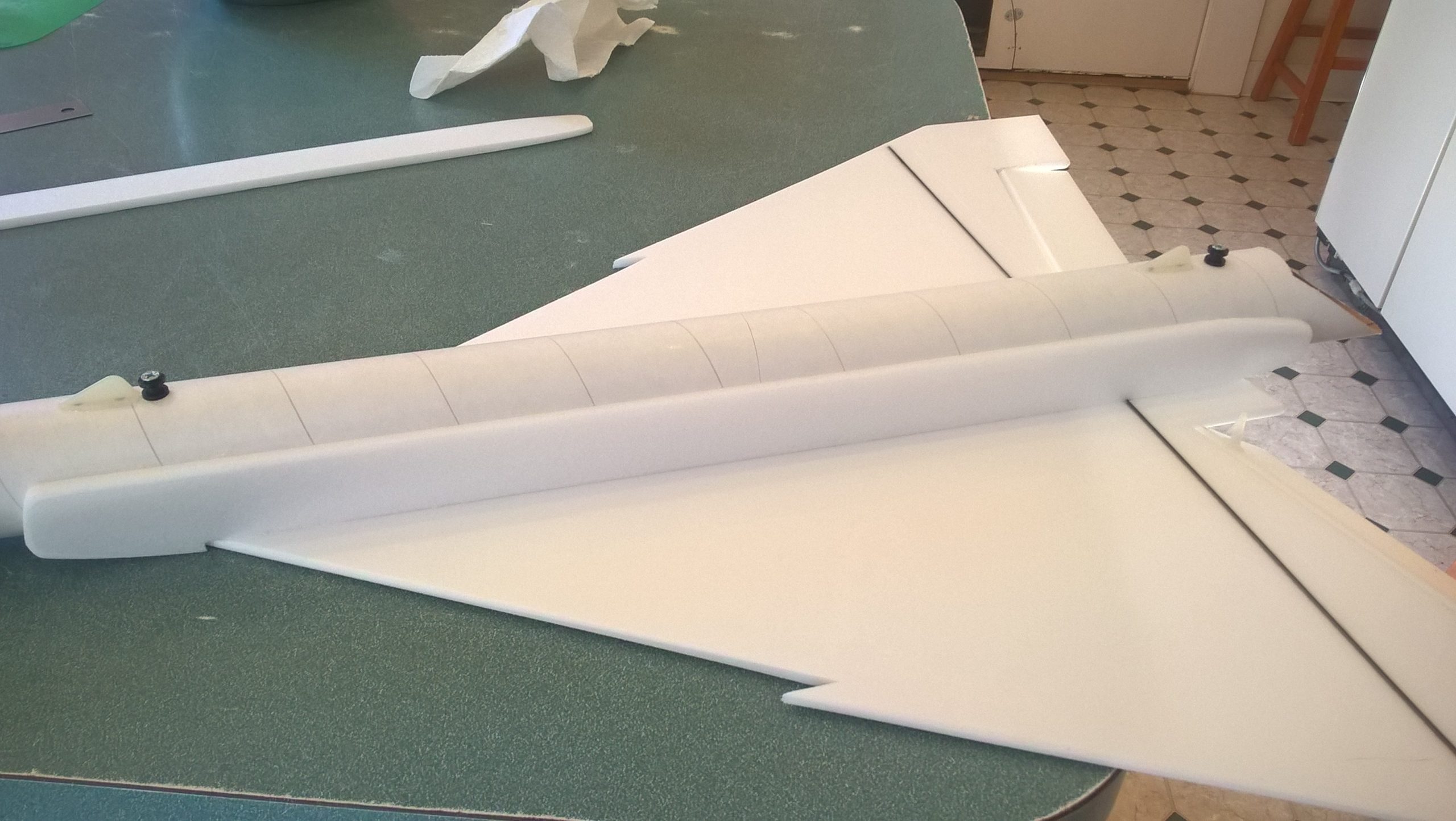
- Glue the intake plates on both sides of the model and to the wing.
-
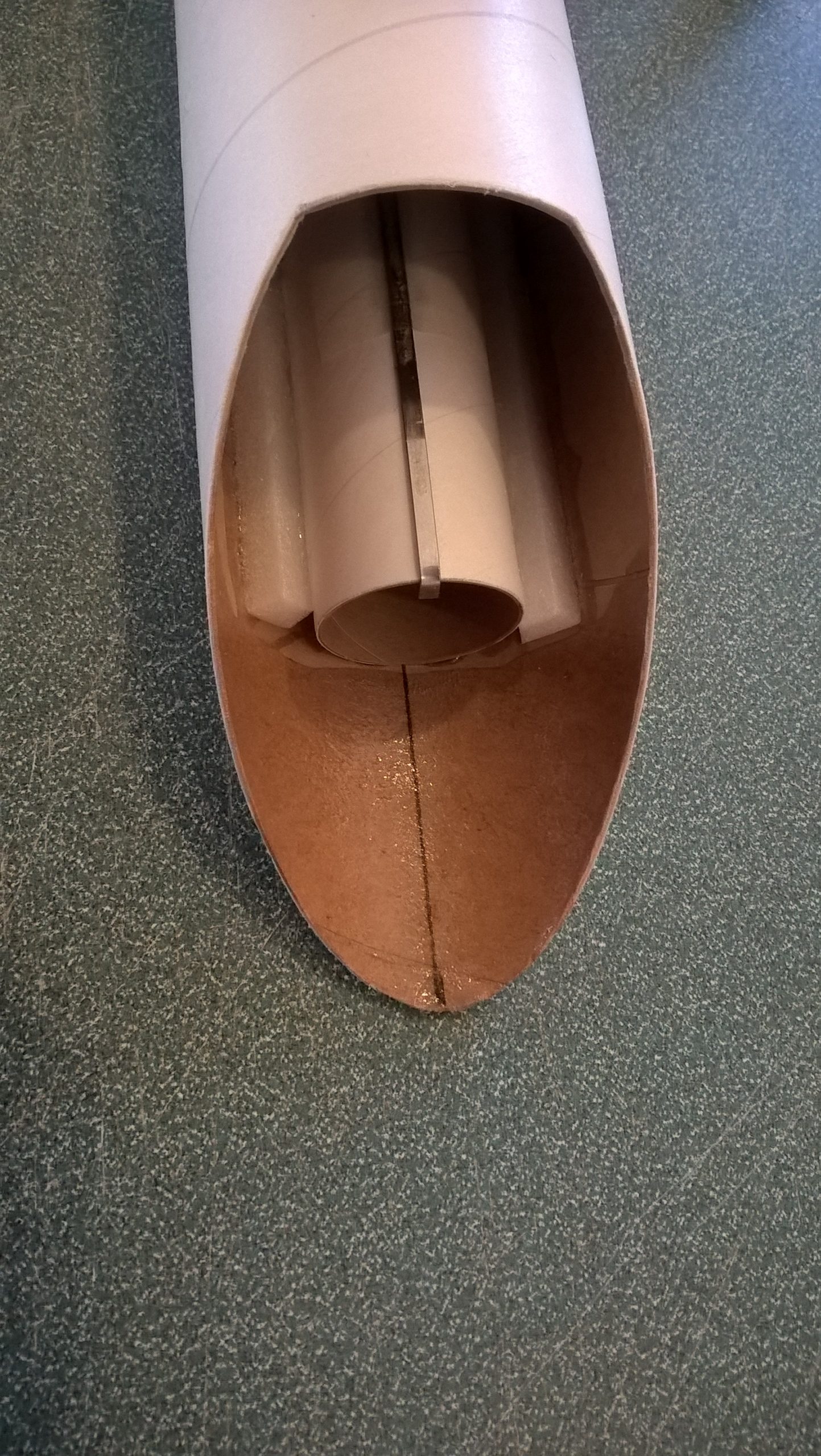
- Glue the motor tube along the alignment line inset 1.75″ and add the reinforcing foam strips on both sides
-
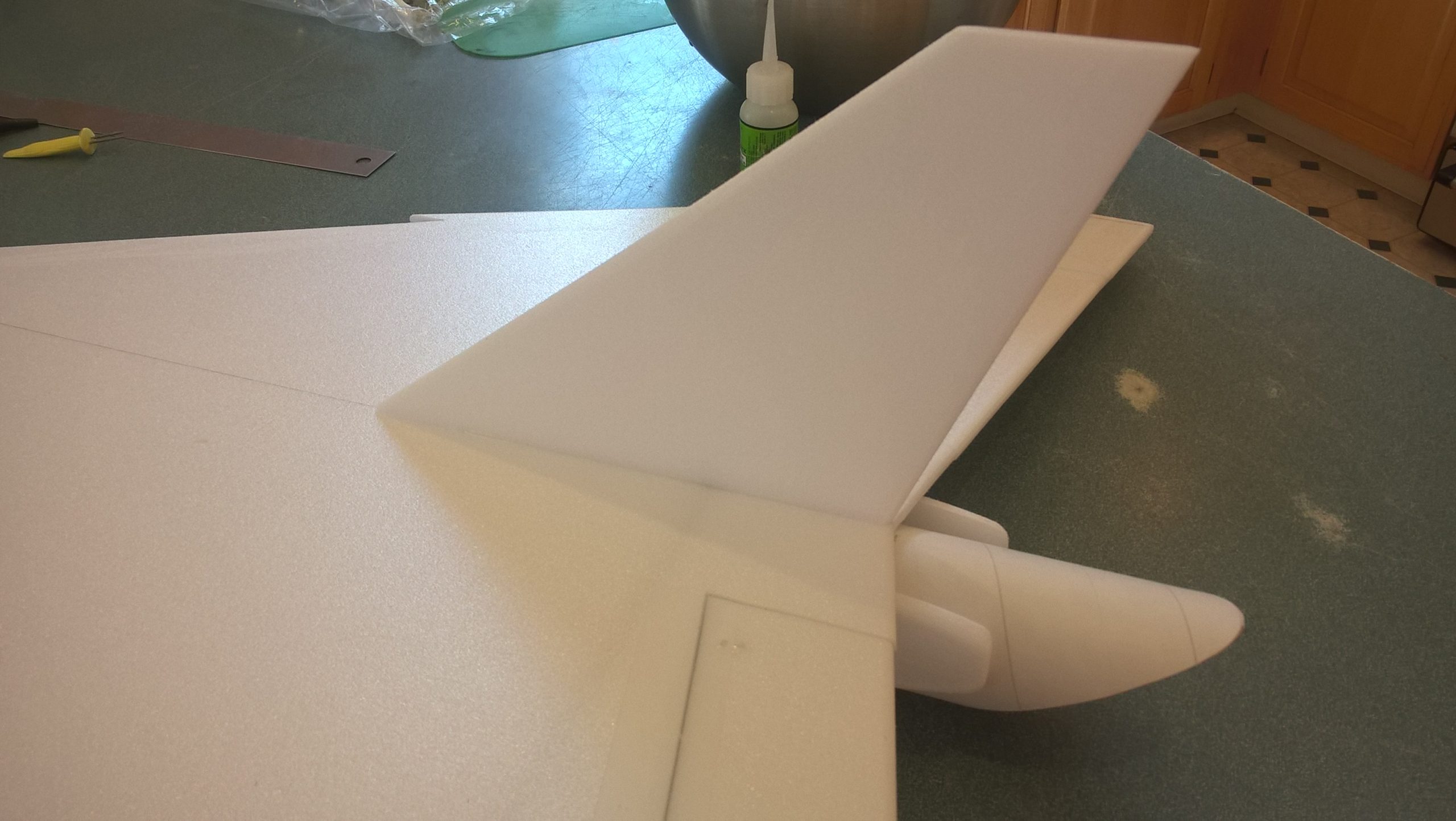
- Glue the vertical stab in place.
-
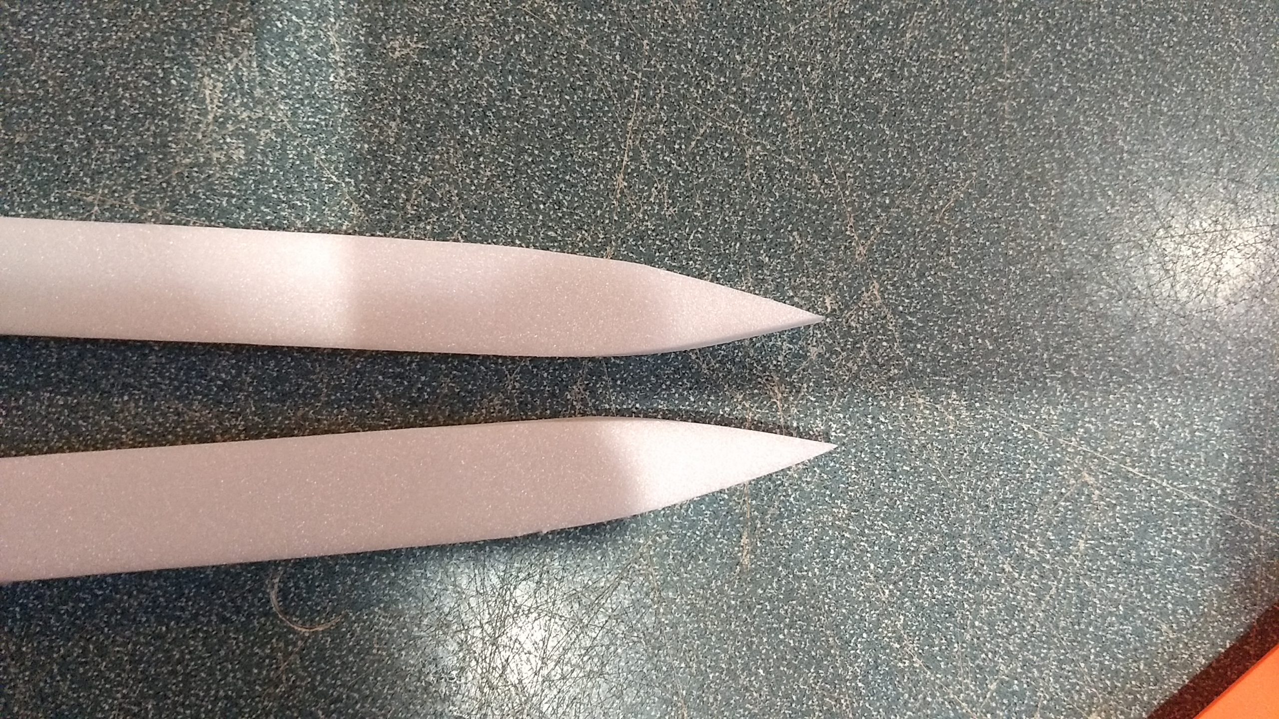
- Glue the short pointed piece to the long conduit/cockpit piece. the short piece will be the bottom of the assembly.
-

- Cockpit and conduit/spine shaping/assembly
-
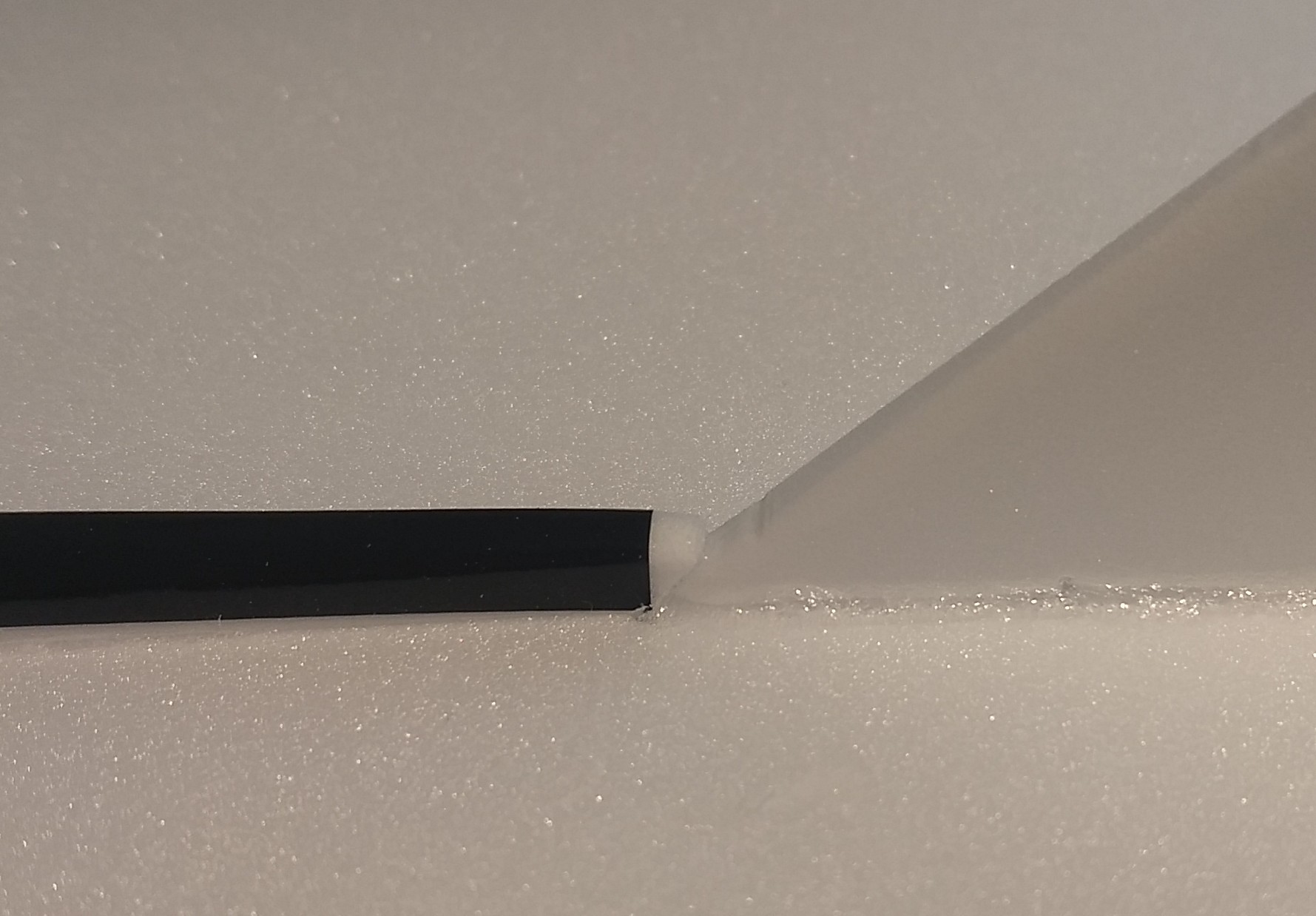
- Showing how conduit is cut to match vertical stab when gluing in place.
-
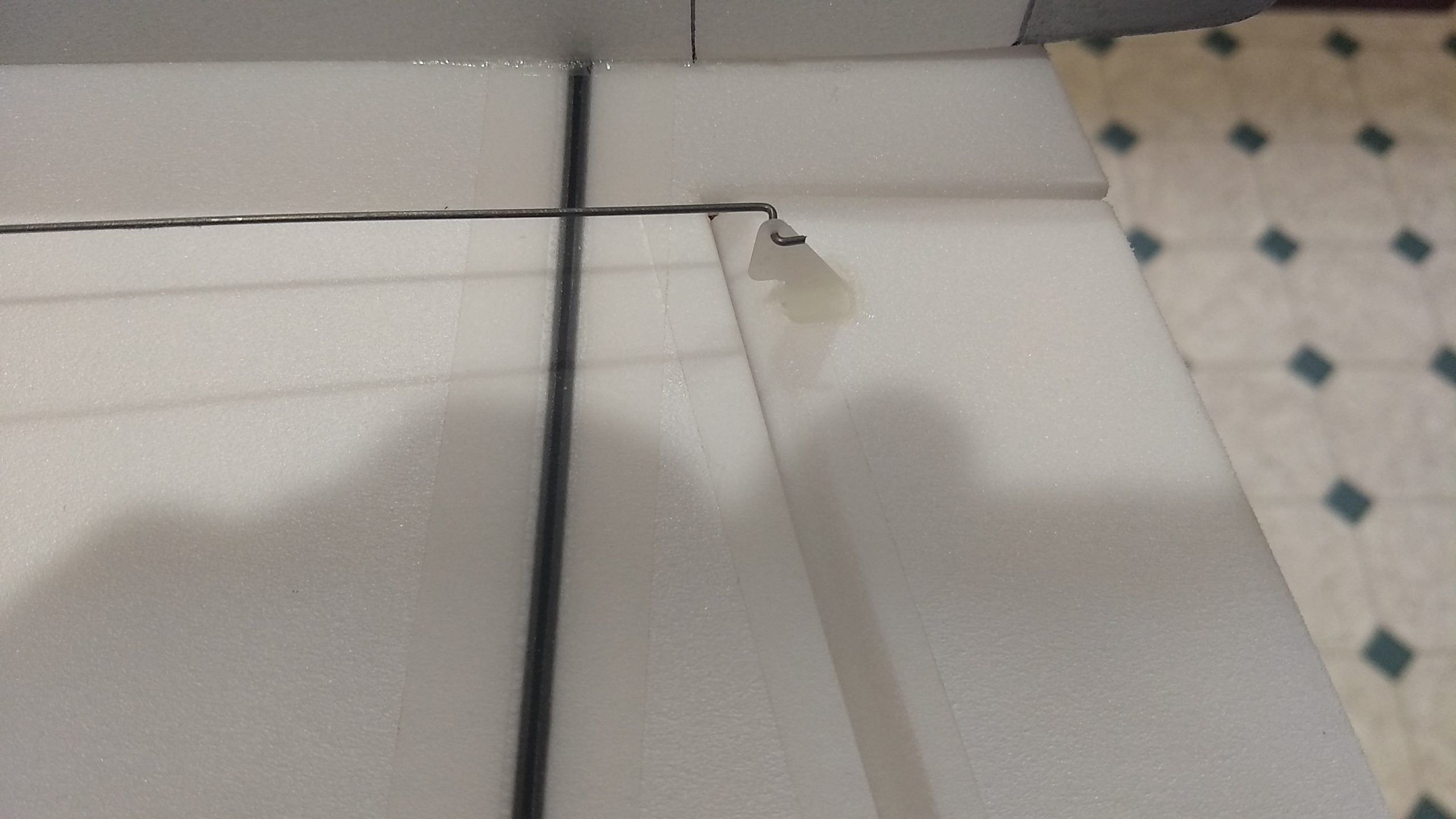
- Glue in the pushrods/control horns on the bottom of the surface using the pre-made holes, if the model does not have pre-made holes for the horn prongs, simply make them using a round toothpick 1″ out from the inboard end of the hinged surface.
-
- apply glue to the top of the control horn prongs to lock them in place.
-

- glue the servo in place and route the servo wire into the body tube on each side.
-
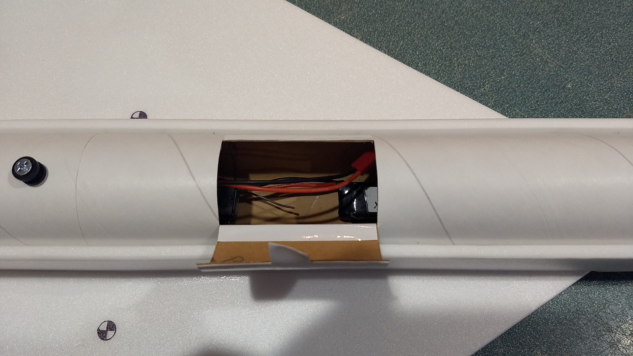
- Cut the hatch in bottom of tube and hinge with tape, install the receiver and battery inside and hook up and test the servo directions.
-
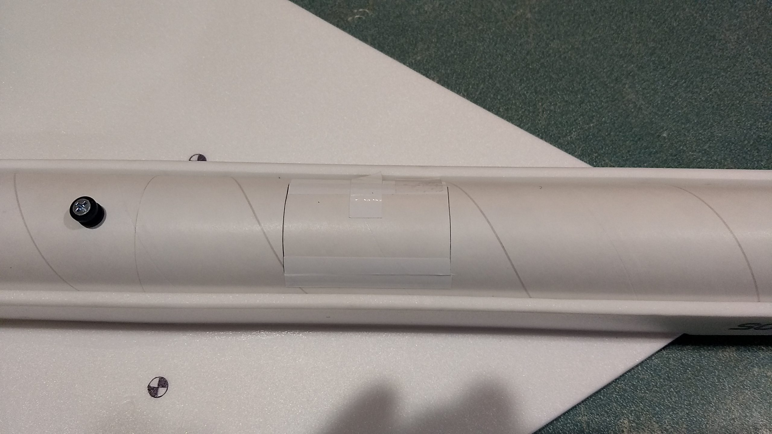
- The hatch is held closed for flight with tape
-
- Alternate method to secure the radio hatch with a screw
-
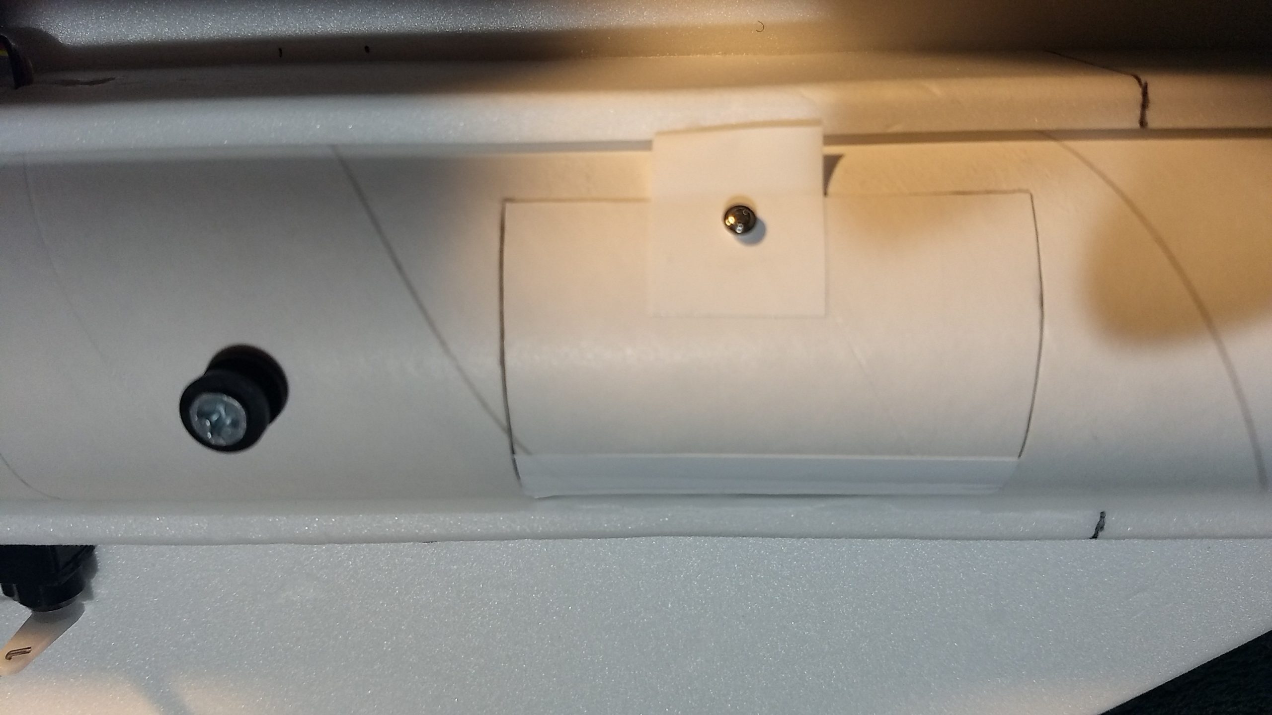
- a little tab of tape to help opening the hatch and the alternative screw to secure it closed.
-
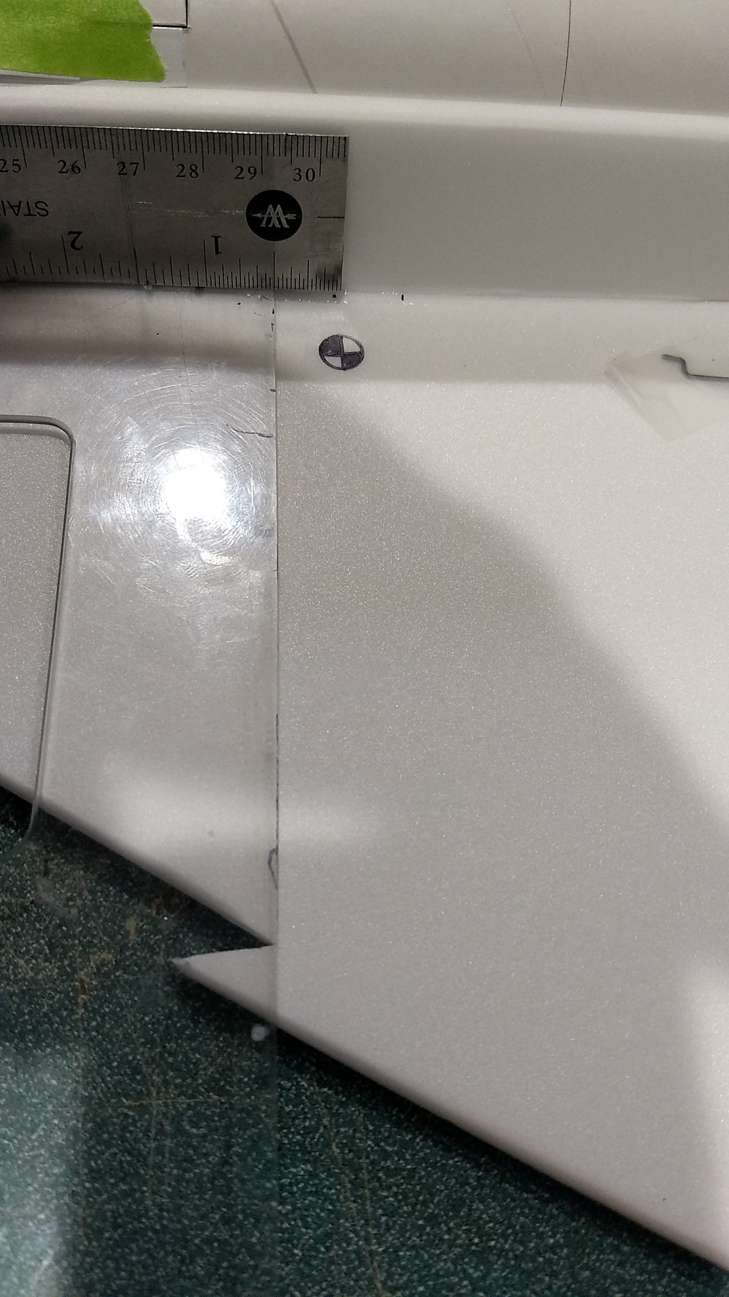
- CG location
-
- left aileron
-

- right aileron
-

- up elevator
-
- down elevator
-
- glide trim
-
- boost trim
-
- neutral trim
-
- Completed model with stickershock decals, panel lines and trim tape wing accents.
-

- 3-view for panel line ideas.
-

- Example of stickershock decals