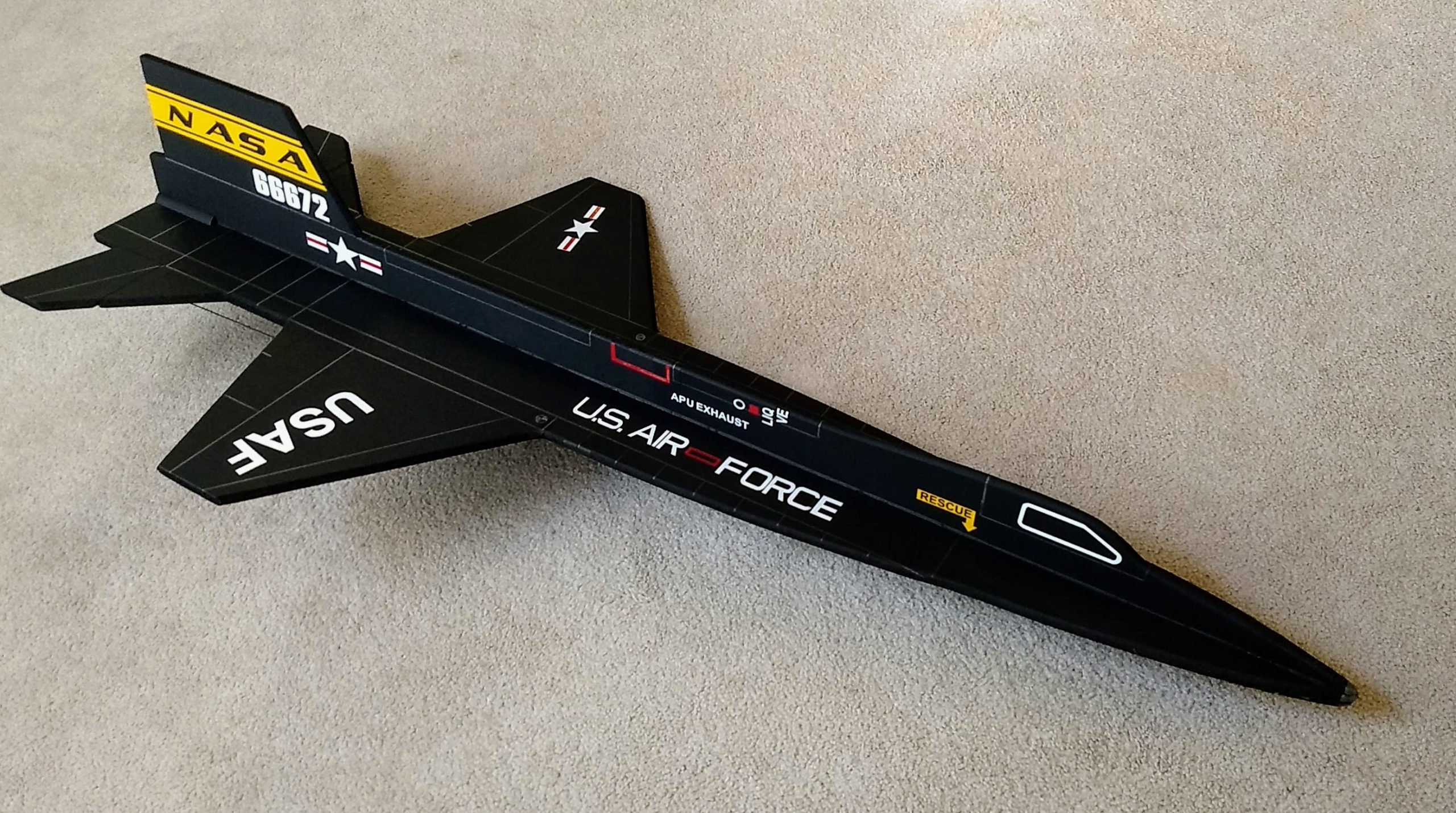
The X-15 RC Rocket glider kit is a profile version of the third X-15 hypersonic reasearch vehicle that flew without the extended lower ventral fin to 67 miles. Construction is very simple and takes about an hour and a half. The kit includes pre-hinged control surfaces, pre-installed spars and pre-cut 9mm depron fuse and wing. Kit includes rail buttons. Length 41″, wingspan 20″, weight 12.5 oz rtf.
Please refer to the General information for all kits tab above, then read these instructions completely before starting assembly. High quality cut vinyl decals available HERE select the white lettering for black model option.
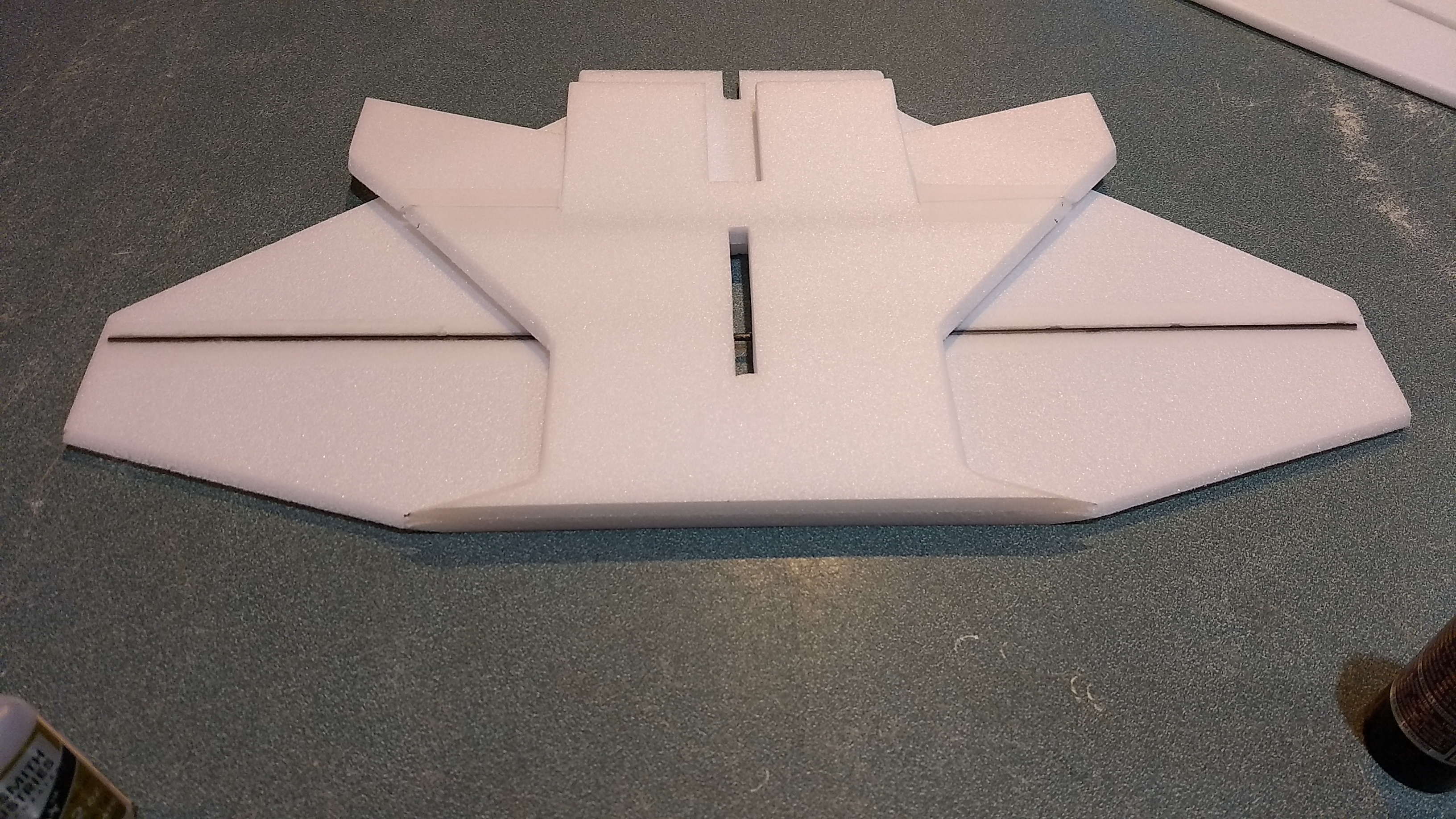
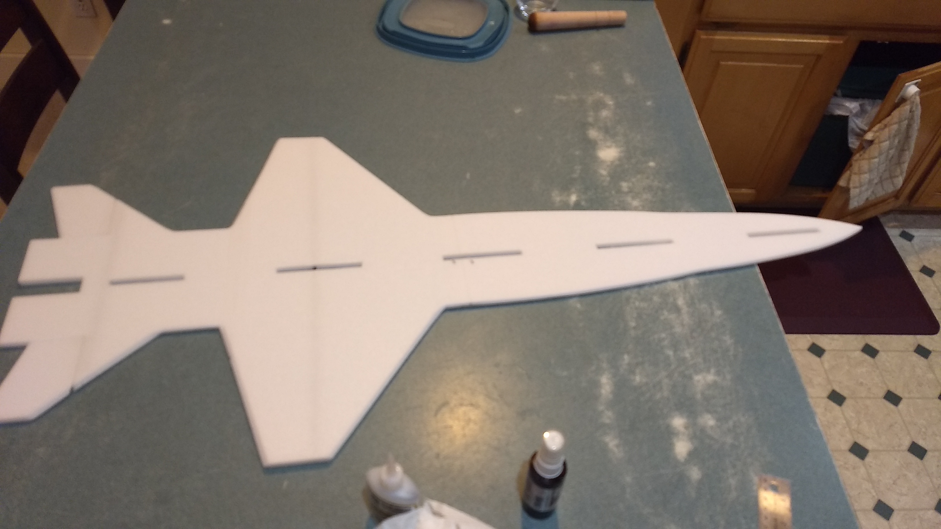
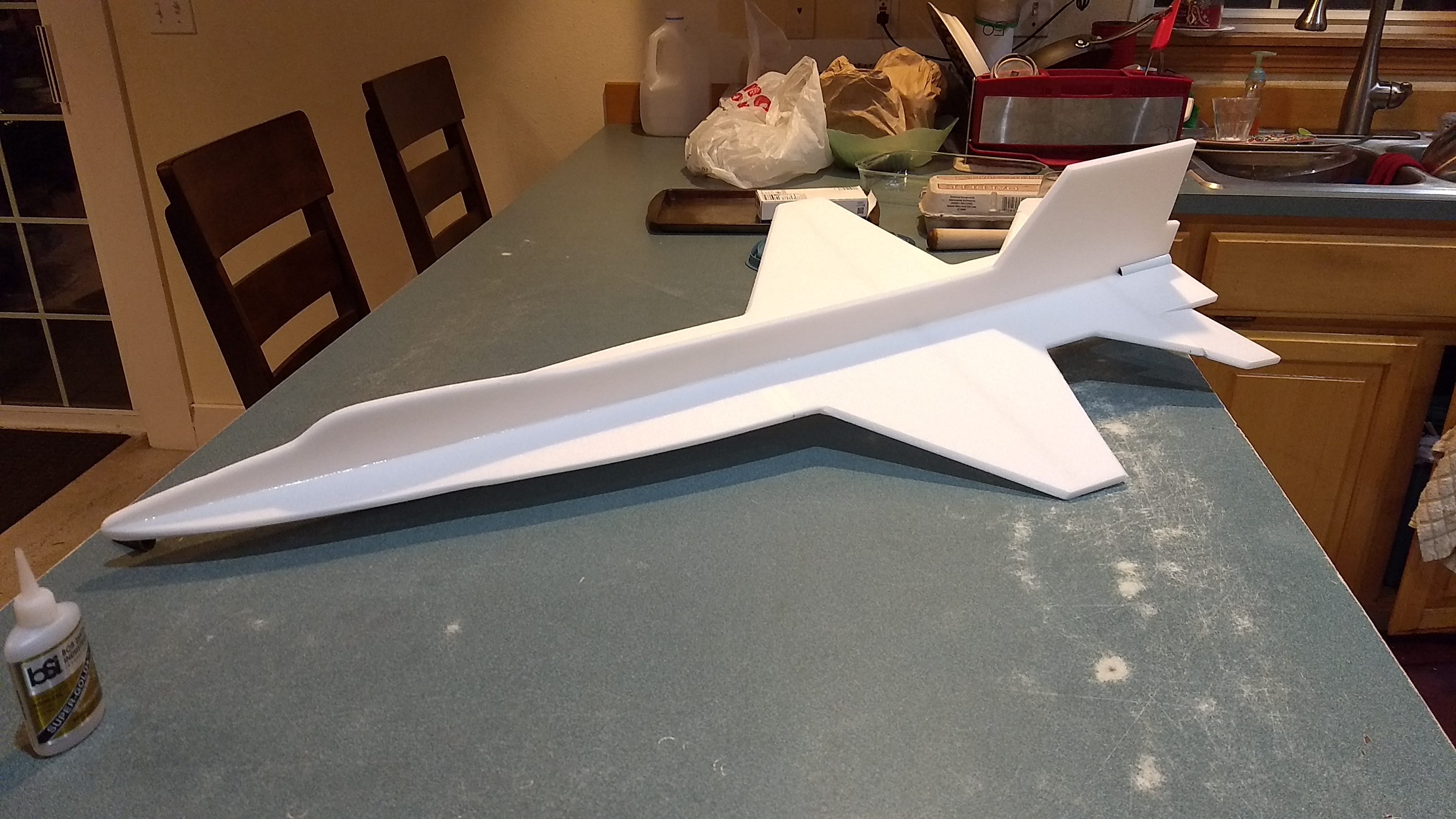
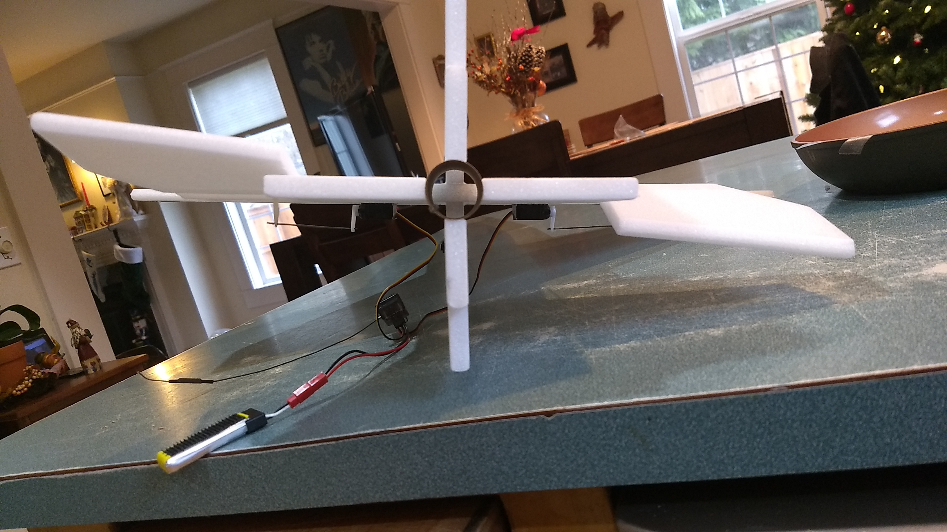
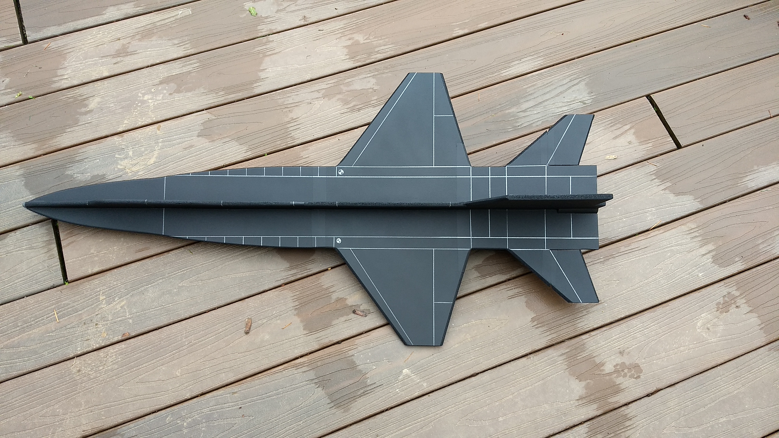
CG location for rocket flight: 18 5/8″ forward from the rear end of the model. See photo below for approx location compared to where the wing/fuselage intersection is.
Unpacking your kit:
The kits are packed to protect them in shipping, but the contents are fragile so unpack carefully. Carefully cut the tape holding the cardboard wing protector in the box and carefully remove it, don’t pull hard or bend it. Then carefully cut the tape holding the cardboard top piece to the bottom. There may be some sticky tape holding the cardboard to the bottom cardboard piece, carefully peel it being sure not to bend anything. Once the top cardboard is free you can see the foam wing/tail parts, there are little fragile pieces in here, so unwrap carefully. It may be best to use an exacto to lightly cut the plastic wrap and carefully remove it without cutting into the foam. Make sure everything is free before you remove the pieces to avoid breaking anything. Kits contain one or two scrap pieces for repairs if you damage anything in construction or flight, just cut and patch in a spare piece of the foam if needed using foam safe CA+.
Welcome to the world of rocket boosted radio control gliders. This is not a model for a novice RC pilot, but anyone who is comfortable with RC flying of a medium speed model should be fine. Read through the instructions, look at the photos and be sure you understand the step before committing to cutting or glue.
Identify all pieces, the kit should contain:
Wing and rear fuse top view(taped together)
2 pushrods
Forward FuselageTop view
Upper fuselage side view(taped together)
Lower fuselage side view(taped together)
Motor mount
Velcro(for battery and rx/bec attachment)
2 Rail buttons
4 styrene rail button reinforcing plates
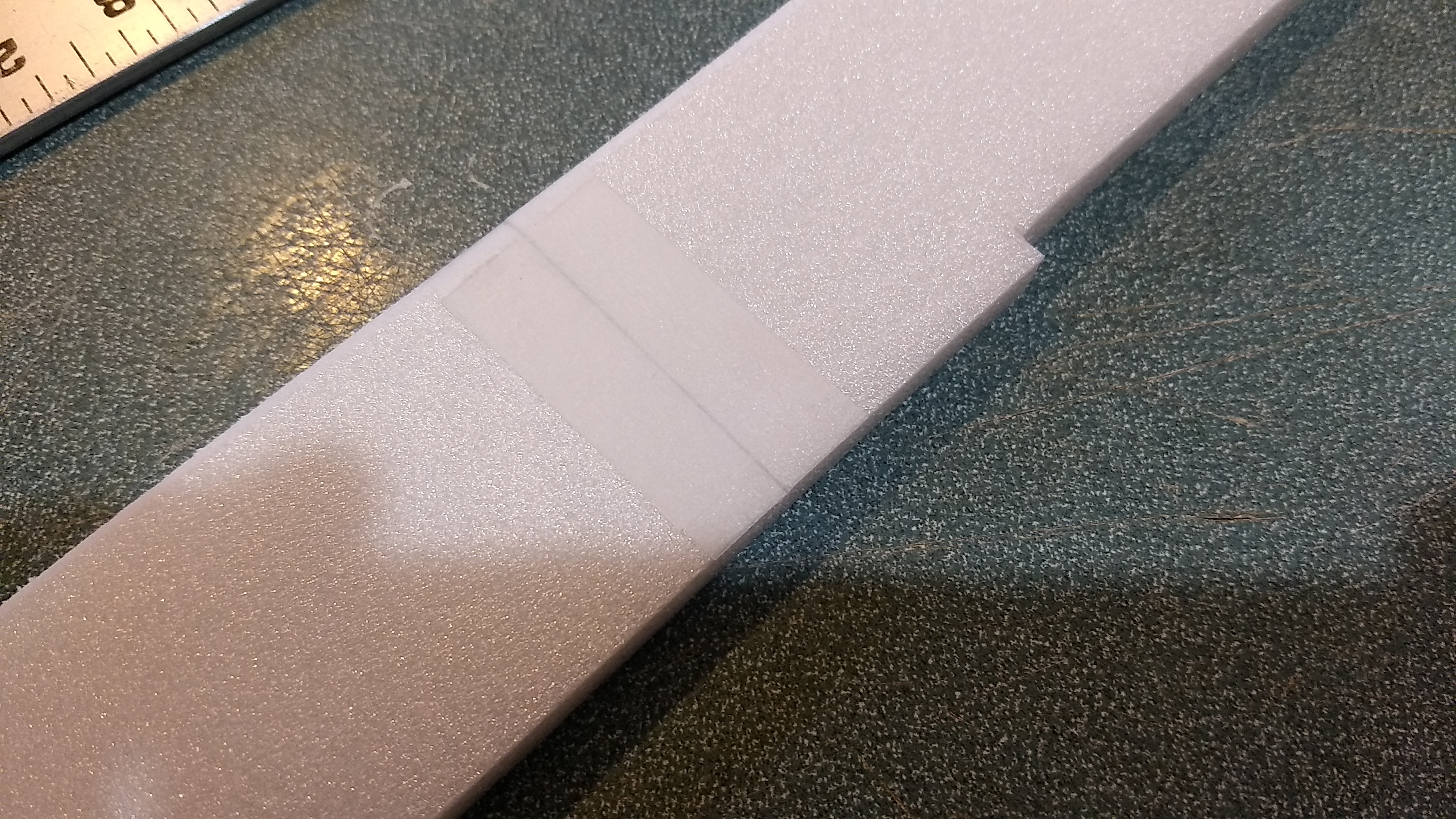
3M blenderm tape
Lead weight
Spare depron
Notes before starting:
Foam safe CA+(Bob smith super gold + is good) is the only glue recommended for construction except for some epoxy just to hold the nose weight in place. You will also need foam safe accellerator.
The 9mm depron is a bit harder to sand and can tear easier with a sanding block, I’ve found it’s better to use a straight edge and sharp exacto to do a 1/8″ to 3/16″ bevel cut on the edges of the wing/stabilizers instead of trying to sand them round. For the few steps that require sanding below use a hard sanding block and 320 grit paper and go light and take your time.
-
- Unfold the top fuselage side view and glue the the seam where it is taped using CA+ and accelerator. Gently bevel the top edges and tape over the seam on the other side.
- Unfold and glue the lower side view fuse piece together at the tape joint. Use CA+ and accelerator, make sure it is straight. Gently bevel the bottom edges of the piece as well and then tape over the other side of the seam.
- Unfold the rear wing piece and glue the joint together using CA+ and accellerator(leave the tape in place).
- Flip the wing upside down so the spars are visible. Tape the forward fuselage top view in place against the wing it will be marked “bottom” so you make sure the piece is facing the right way, make sure it is straight and aligned, use 3m blenderm tape.
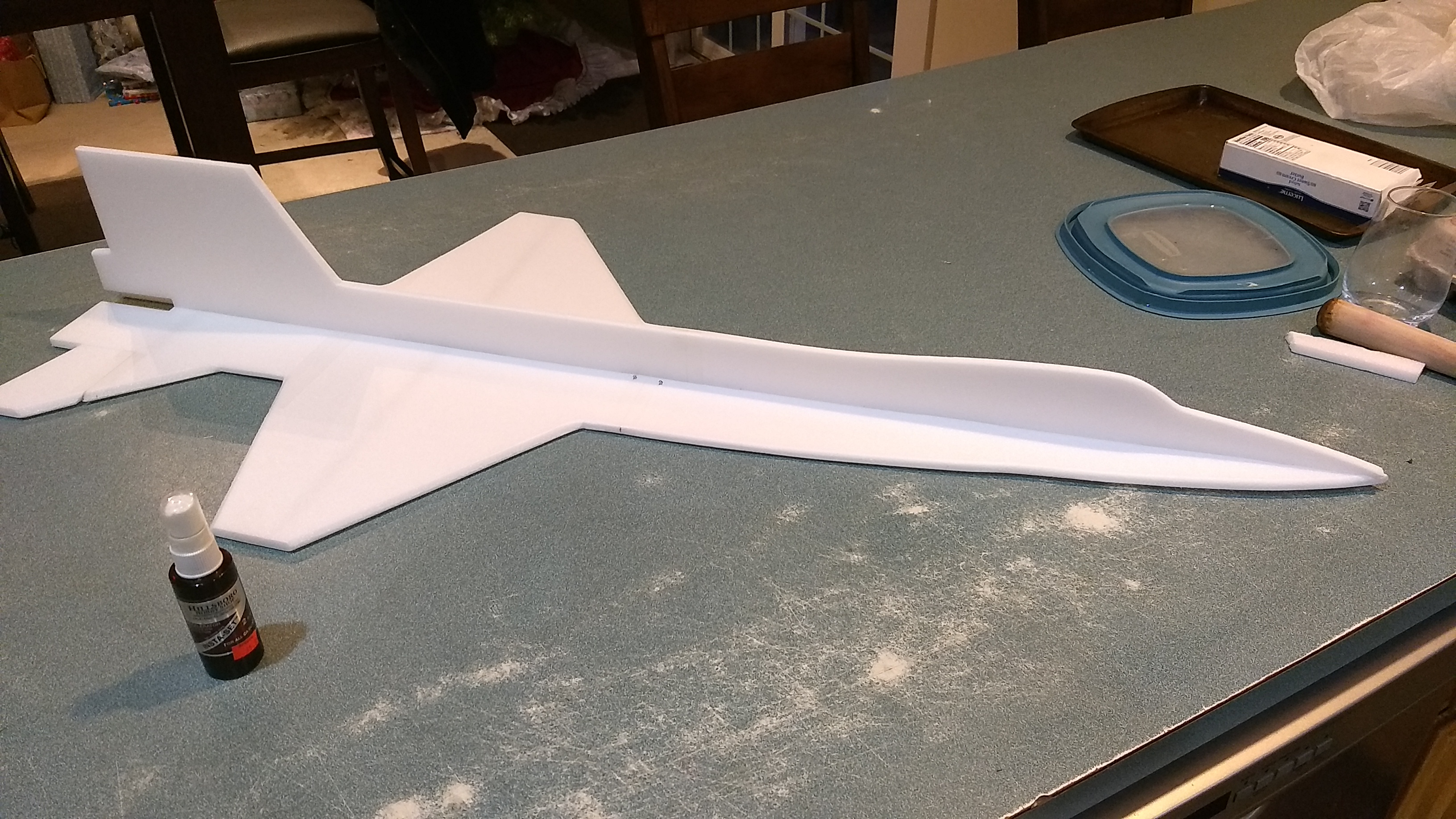
- Flip the model back over and then glue the joint together using CA+ and accelerator. At this time you should bevel all edges of the model for a nice shape. It is not required but will look much better. Once done tape over the top front and rear glue joints to hide them and give them some support.
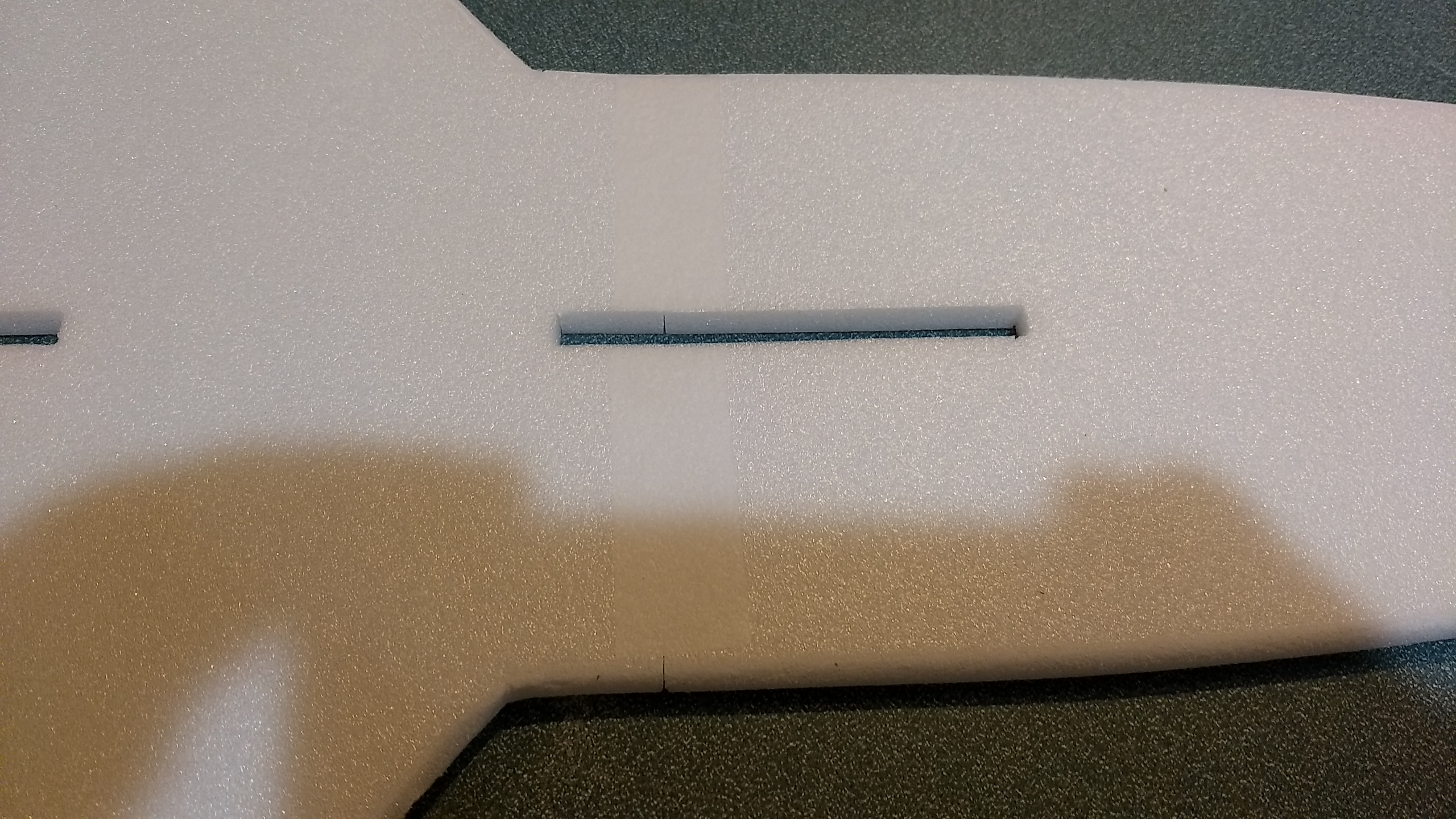
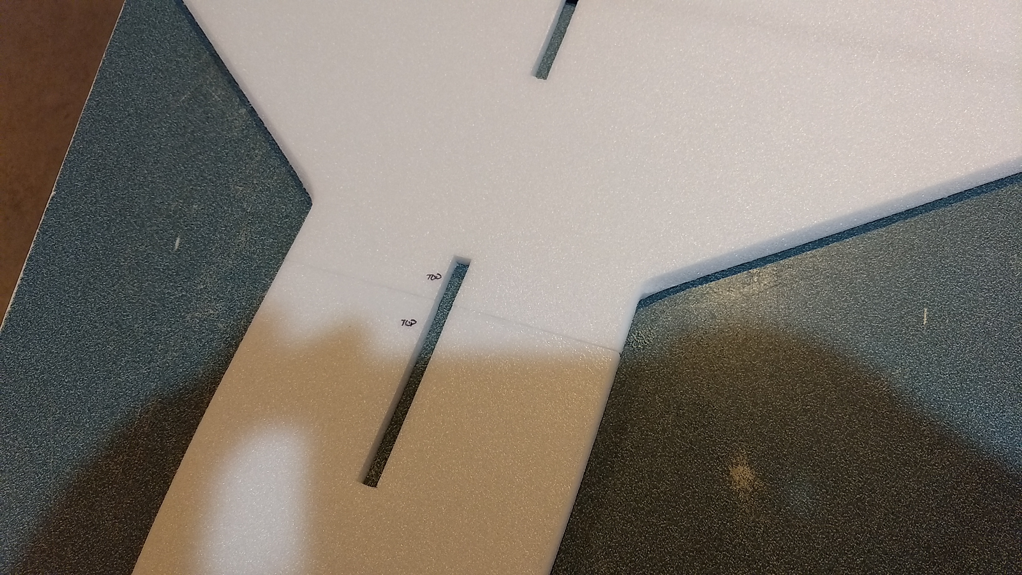
- Test fit the top side view in the top of the fuselage, be careful to not break off the tabs, the tabs should align the fuse side view straight, The foam compresses slightly so it is ok to press them in place. I seat the front tab then work my way back till all are seated. You can also break the edges of the tab corners lightly with a sanding block to help them start into the slots the press in place and make sure it is fully seated and the top view stays flat. Apply a bead of CA+ to both sides of the joint.
- Pick up the model and fit the bottom view into the slots in the same way. Make sure it seats fully, Flip the model over upside down, lay it so that half the model is laying on the edge of a table so it is suported flat and put a weight on the wing half to keep it from falling off and make sure it is still flat. Glue it in place.
- Test fit the motor mount into the rear of the model. Make sure it fits or trim the foam lightly till it will insert. Make sure the vertical stab is not curved at the rear. Make sure the motor hook is not blocked by the foam and can be reached to release the motor and use CA+ and make a bead on each joint and set it with accellerator. Make sure the motor tube is attached well but don’t overdo it and don’t use epoxy, tail weight is a killer and there isn’t much force on the motor tube during launch. The foam is plenty strong enough to support the forward thrust and no thrust ring is needed. I’ve flown many flights and the forward foam has never melted or failed.
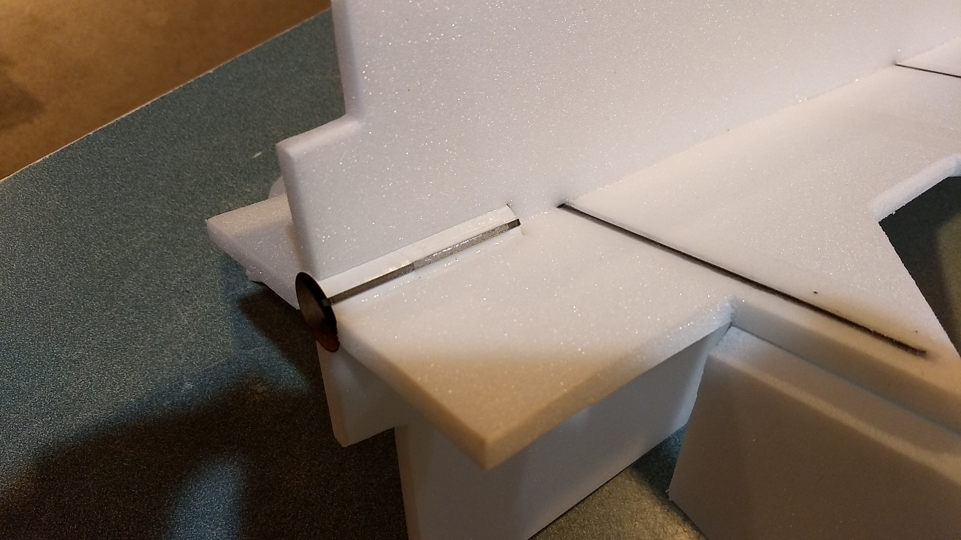
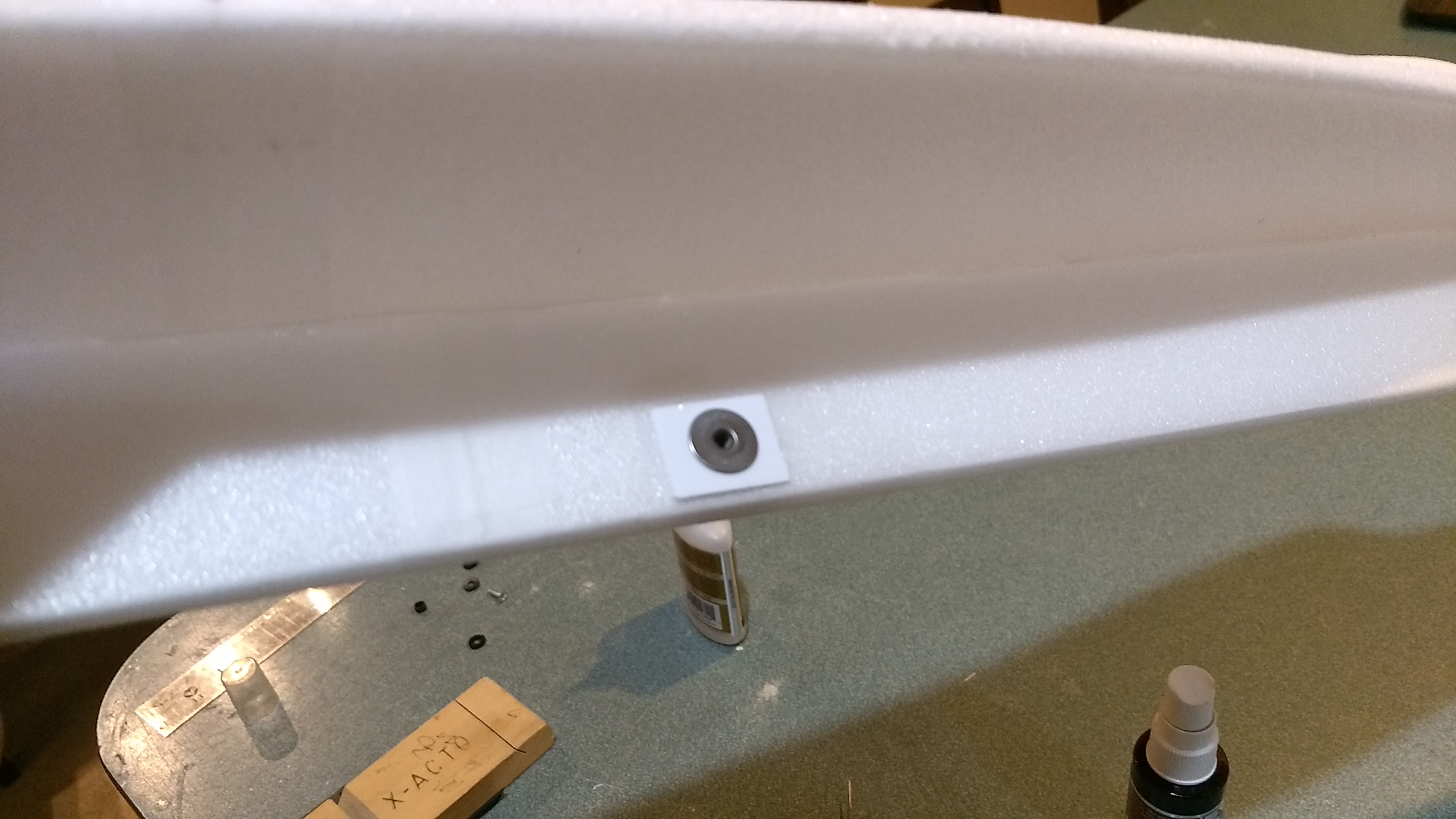
- Glue two of the styrene rail button plates at the two places marked on the foam.
- Use a screwdriver to poke a hole through the plate and through the foam to the other side.
- Using the holes as a guide glue the other two plates in place on the other side of the model. Insert the t nuts from one side then install the rail buttons using the screws provided. Don’t tighten down too hard and crush the foam.
- Glue the pushrods/control horns into the holes premade into the bottom of each control surface, note the pushrod should be closest to the fuselage, there is a left and right. See picture for clarity.
The basic construction is now complete.
Radio Installation
Note: Your radio needs to be configured for Delta mixing, this means that the servo arms will move the same direction during elevator stick movement and opposite for aileron stick movement. Connect your servos to the receiver one in the aileron connection and one on the elevator connection and apply power. Use a servo arm at least 9/16” long and with holes small enough that there won’t be slop with the pushrod wire when installed. I use the hole furthest out on the servo arm, to maximize movement. On some servos there are a long two-ended servo arm, you can trim off one end if needed to get sufficient length. Zero out any trim settings on the transmitter. The model once the motor has burned out is nose heavy and flying wings lose pitch authority when nose heavy so you want as much up elevator travel for trim/flare as possible.
- Install the other end of the pushrod to the servo output arm, again making sure the servo wire is toward the fuselage side of the model. If the wire is too tight, you can use twist an exacto knife in the servo arm hole to make it larger, but be careful and do not make it too large. Repeat for the other side. Once connected, tape each servo in place so that the control surfaces are centered. Flip the model right side up and look at it from the rear. Moving the transmitter stick back(up elevator) should move both stabilizors TE’s up. Moving the transmitter stick to the right should move the right TE of the stabilizer up and the left one down. If you can’t get the servo reversing to give you the right polarity try swapping aileron/elevator inputs to the receiver or turning the servos over and swapping the servo arms to the other side of the output shaft. If that is correct, continue.
- Flip the model upside down and supported. The servos may be attached to the model using double back servo mounting tape(not included) or by directly gluing the servo to the wing with CA+ or a small amount of epoxy. Double back servo tape can loosen over time and with exposure to heat, I prefer to glue the servo in place. With the radio still on, put a small amount of glue on the servo, being careful not to get any near the output shaft. And set it in place on the model keeping the control surface centered. Do the same to the other side. Make sure the glue is set before continuing.
- Flip the model back right side up. Make sure the control surfaces are centered, use trims if needed. Now measure the control surface movement. Full elevator and aileron movement should be 1.125-1.25” in each direction. Since the model will be nose heavy, extra stabilizer movement helps to give sufficient authority during glide. Roll rate is not extremely fast during glide so you need plenty of movement. Set up dual rates with lower movements if you are worried but boost with higher settings till you are comfortable.
- If you have a flap/elevator mix you can program up elevator to a switch setting. The model needs approximately 1/2” of up elevator during glide. Boost will use completely neutral settings for the first flight. If you can’t set the up elevator to a switch on your radio you’ll have to manually put in glide trim which is hard to do while flying the model.
- The receiver and battery will be mounted on the side opposite that that has the rail buttons attached so the rail won’t hit your radio equipment. Cut a small slot into the foam and pass the servo wire that is attached to the servo on the same side as the rail buttons over to the other side, you can then plug the slot with a spare piece of foam.
- Attach the servo back to the receiver. Tape down the servo wires and then mount the receiver on the model using the included velcro as far forward as the wires will allow, then mount the battery using velcro as far forward as the wires will allow.
- Make sure your controls are still moving the right directions and proceed.
- Insert a loaded rocket motor into the motor mount. Use the heaviest motor you plan on flying.
- Support the model at the balance point indicated for boost. I use two pencils with rounded erasers pointed up and held in place with a small hand vice. Place the model upside down on the pencil erasers with the erasers just behind where the leading edge of the wing intersects the top view of the fuse as indicated in the plans so that the model balances slightly nose down. On my model I needed around 3 oz of nose weight. I put the lead shot in a baggie and taped it to the nose to figure out how much I would need.
- The epoxy will weigh a little bit, maybe a half an ounce or so, so remove a bit of the lead shot and set aside then mix the shot in with a bit of epoxy and distribute it under the nose on both sides. When cured, double check the balance is still good. If it is a little light, use some CA+ and attach a little at at time till it balances slightly nose down. It may look a bit messy but once painted you won’t really see it.
- Do not fly the model with it balancing it behind this point. The adage is, a nose heavy model flies poorly, a tail heavy model flies once.
- To paint the model you can remove the receiver and battery, rail buttons and t-nuts and mask off the servo plugs and Velcro strips on the model. I use Model Master(testors) or testors small rattle cans for painting directly on the foam. Model master flat black is perfect. I paint the edges first since those tend to soak more paint and need re-coating first, then do the flat areas. It took slightly more than one can to do my prototype.
- Use a silver sharpie to add panel lines if desired.
- Re-install the receiver, rail buttons and battery and loaded motor, double check the paint did not change the balance point.
Flying: See the General Instruction link at the top for flying instructions. Be ready on the first few flights to keep the model straight till you have the trims set perfectly for boost and glide.
-
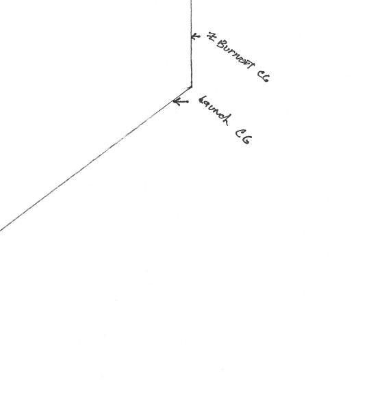
- Top view, CG Location, Up is the front of the model, this shows the left side of the wing….
-
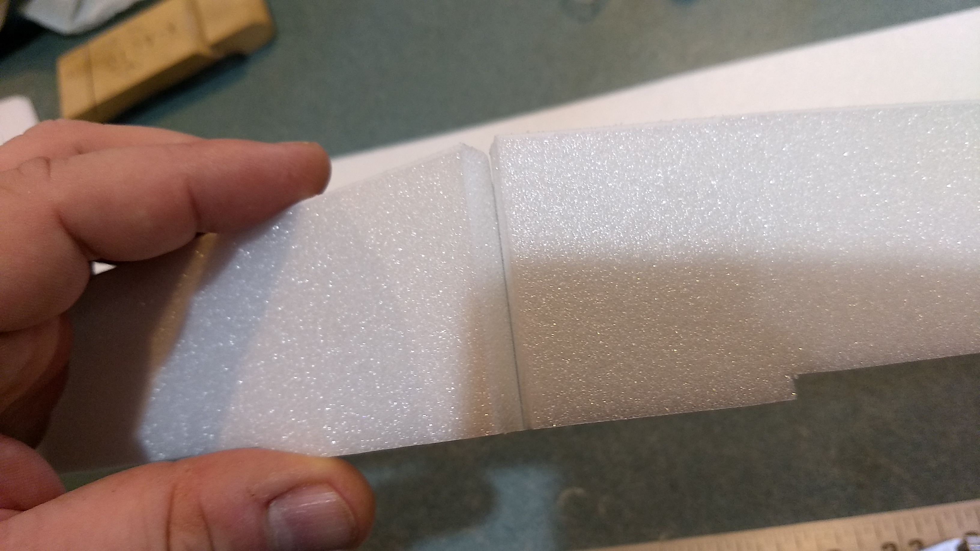
- Unfold the top fuselage side view and glue the taped joint.
-
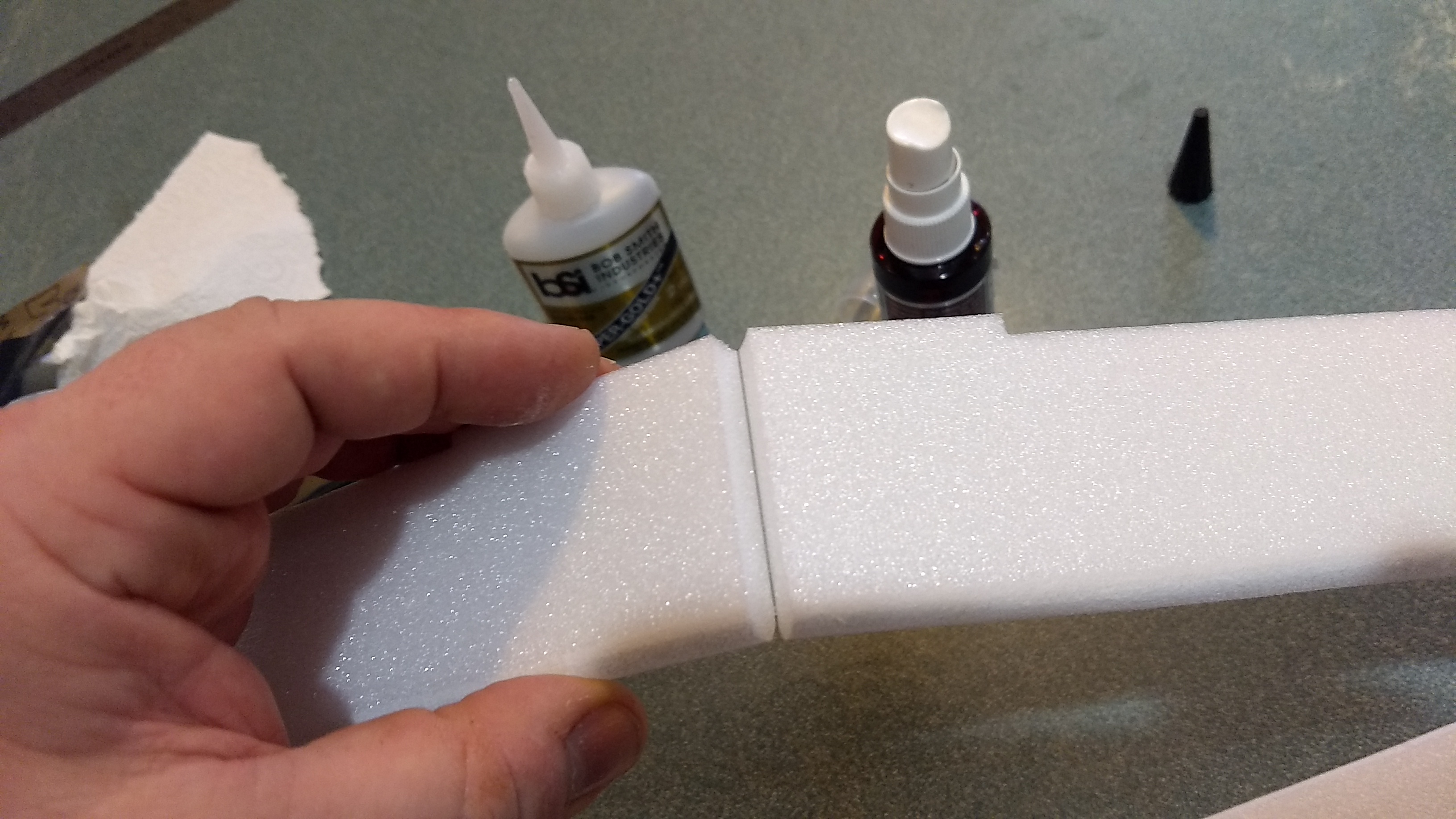
- unfold the lower fuselage side view at the taped joint
-
- Bevel the edges on the parts that do not have tabs then tape over the other side of the glue joint.
-
- Unfold the fuselage top view wing/tail section.
-

- Glue the taped joint
-
- Turn the fuselage upside down(spars will be visible, then tape the forward fuselage top view in place with included tape
-
- Turn the top view over and glue the forward taped joint
-
- Bevel all edges, then tape over the top of the forward and rear glue joints to hide the seam and reinforce the joint.
-
- Test fit then install the top side view into the slots in the wing, make sure it is straight and flat and glue in place.
-
- Test fit the lower fuselage side view into the slots, and push them in place till they seat fully, then lay it on the edge of a table to make sure it remains flat. Then glue in place.
-
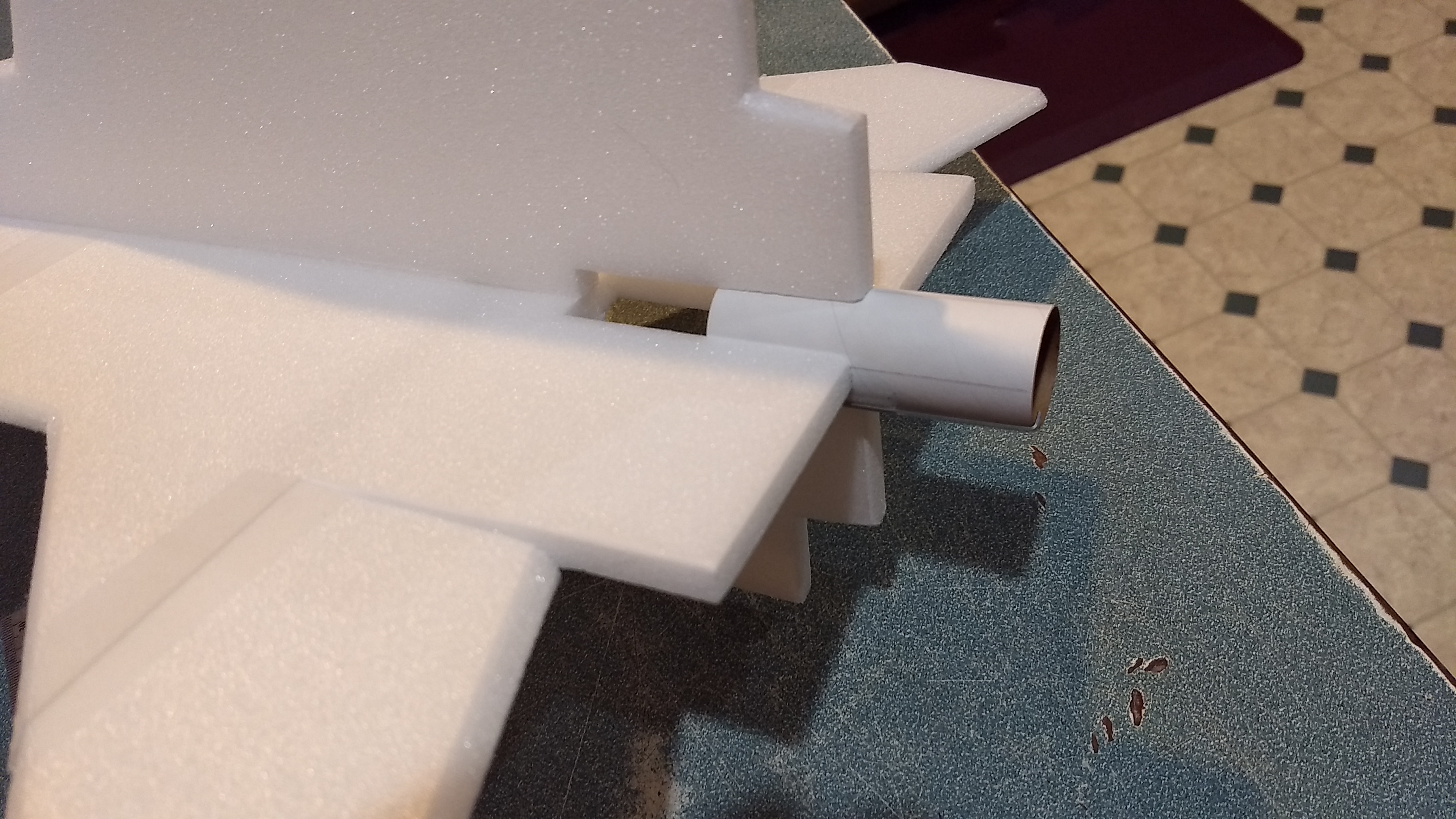
- Test fit, then install the motor tube.
-
- Note how the motor hook is offset so the hook can move. Glue in place with foam safe CA+
-
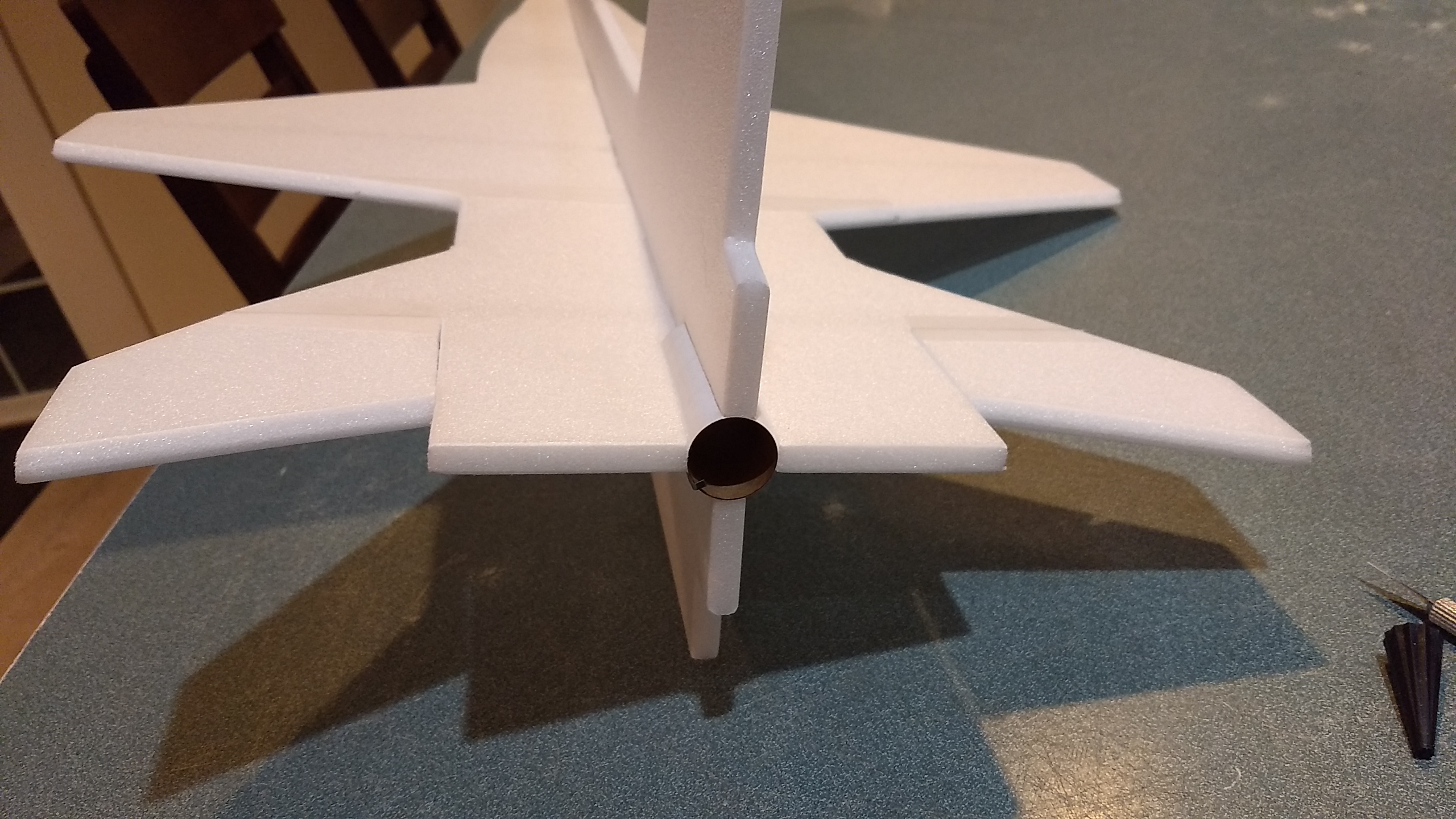
- Rear view showing motor mount installed.
-
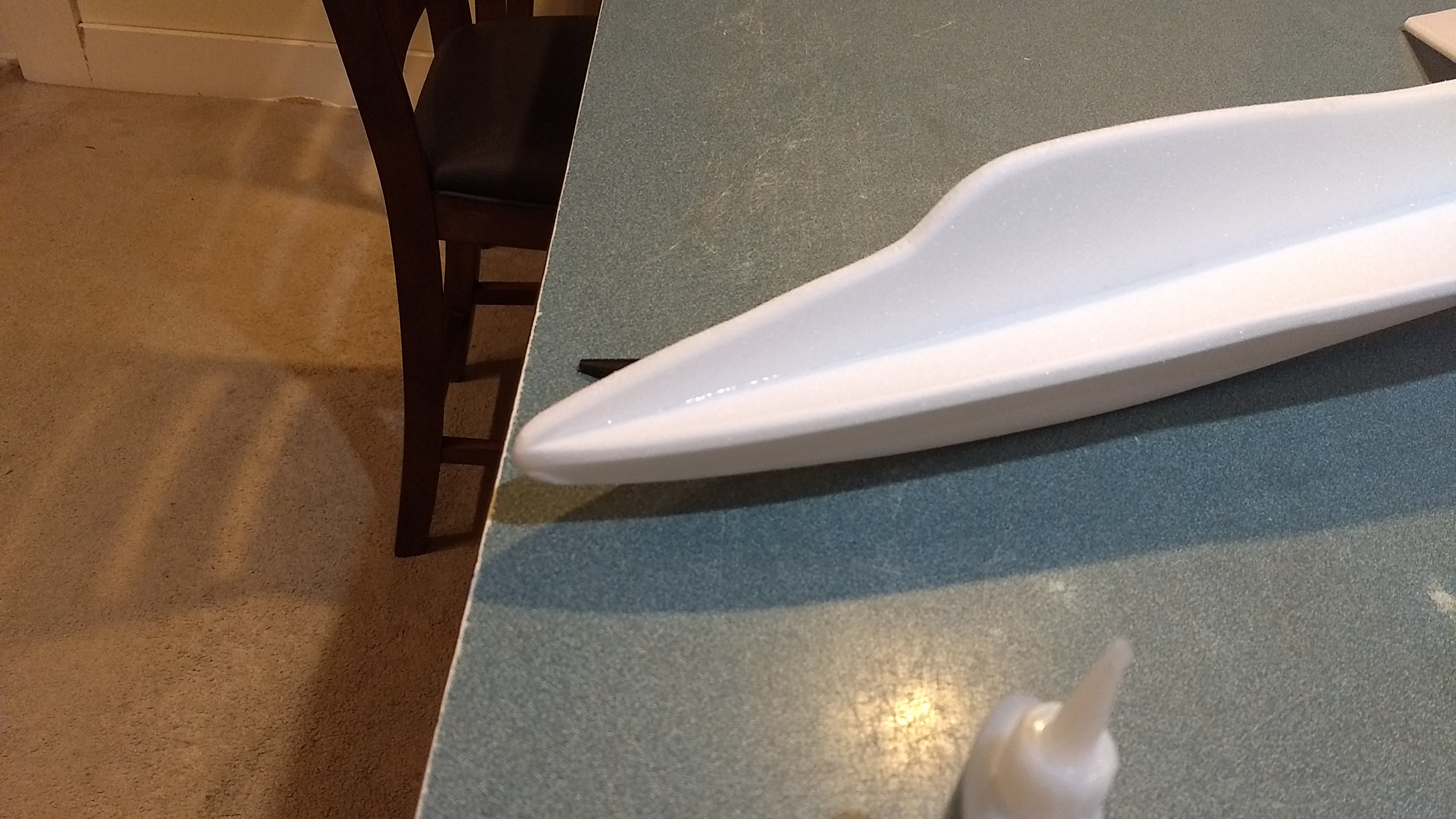
- Dress up the front to blend in the top/bottom side views and the top view to a nice rounded shape.
-

- Glue two of the rail button reinforcing plates on one side of the fuse on the locations marked.
-
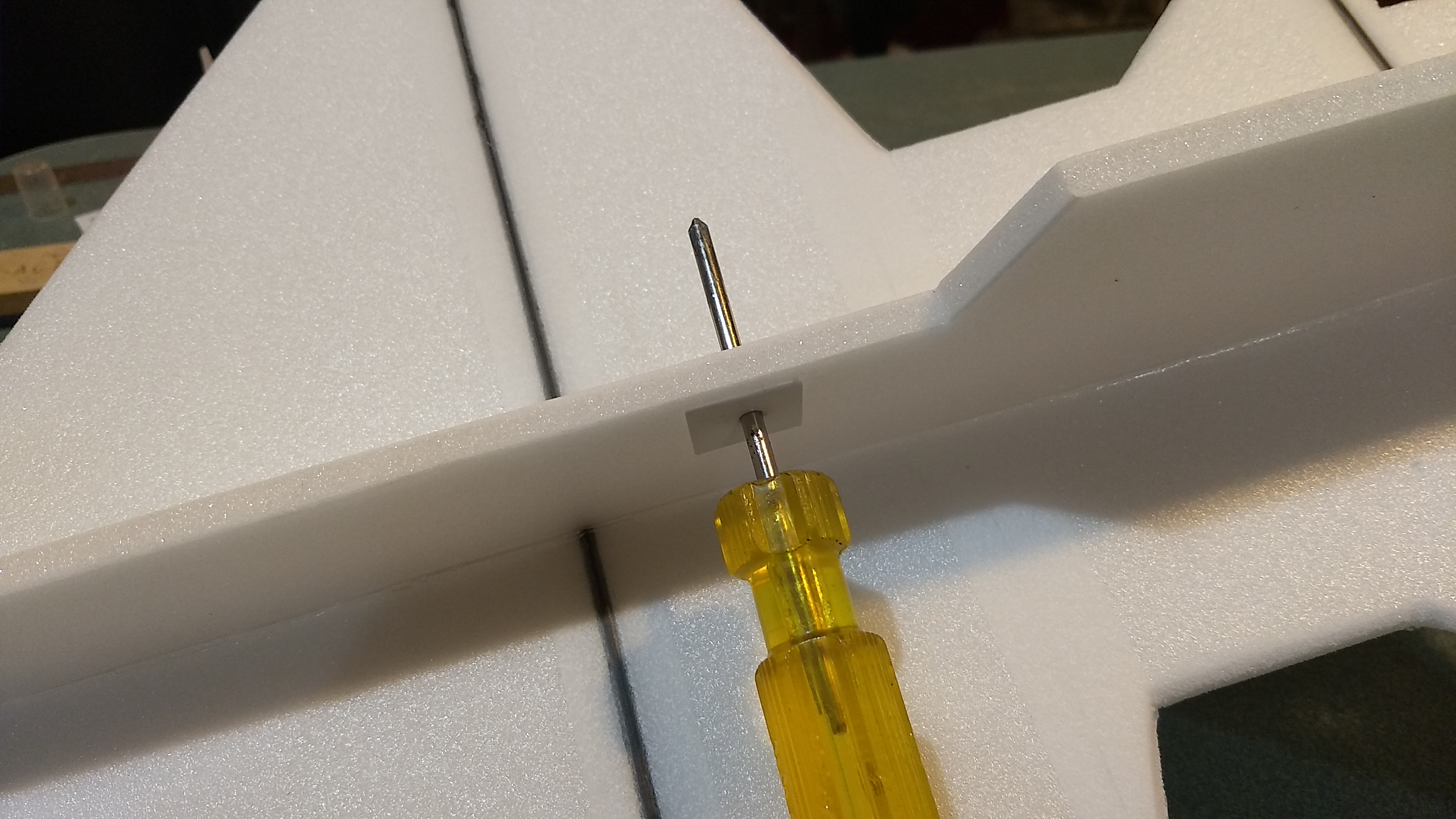
- use a screwdriver to poke a hole through the foam through the reinforcing plate.
-
- Glue plates on the other side of the foam using the holes as a guide, then insert the t nuts.
-
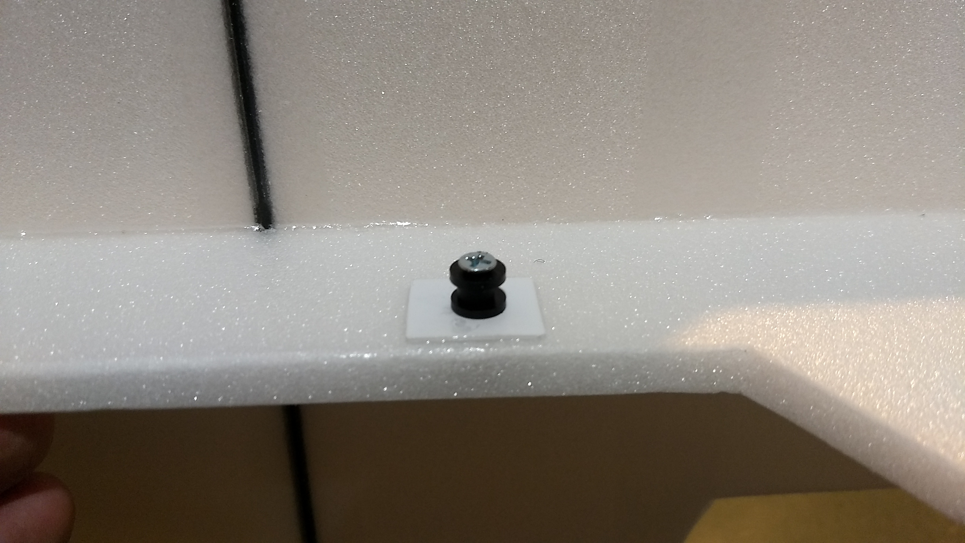
- Install the rail buttons using the screw, don’t tighten down too hard and crush the foam.
-
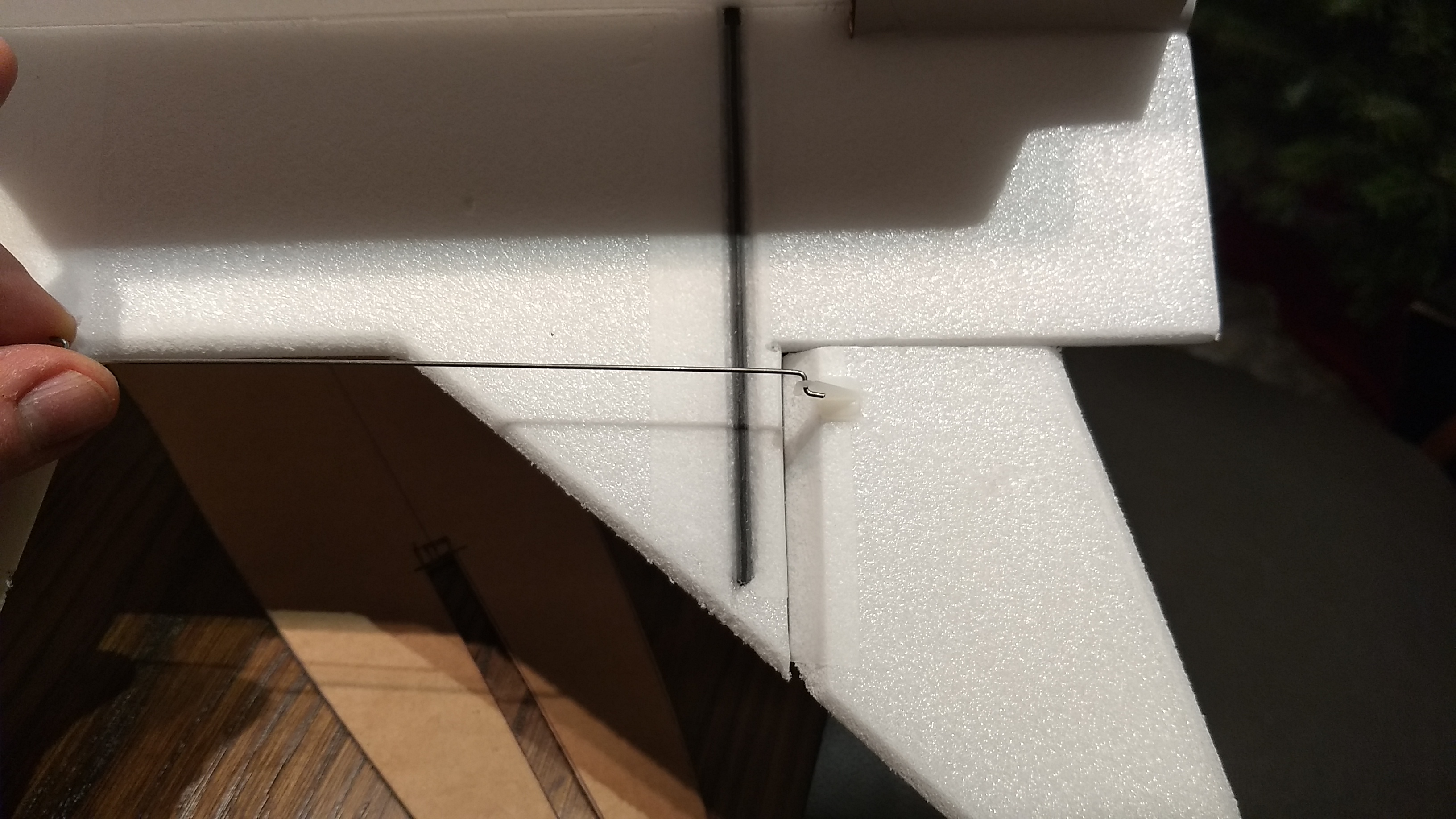
- Glue the two pushrods/control horns in place in the holes pre-punched in the bottom of each control surface. Note how the pushrod is closest to the fuselage.
-
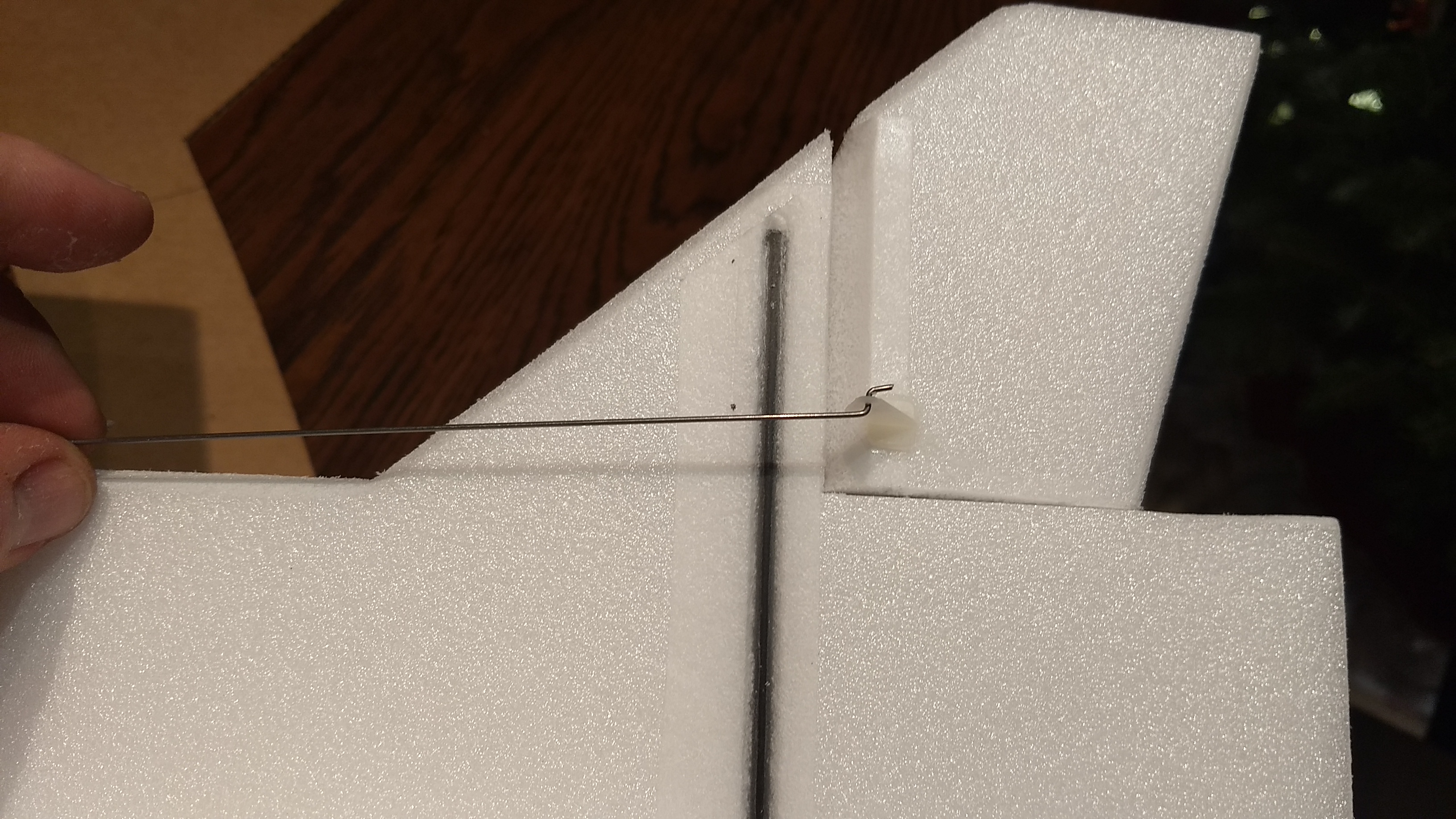
- Make sure the horn is well glued
-
- Airframe completed
-

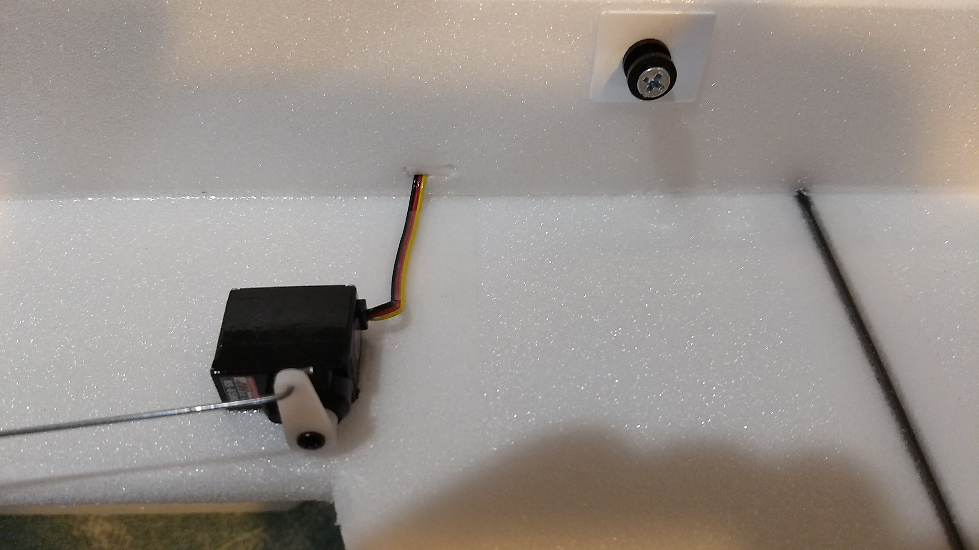
- Attach a servo to each pushrod, note the orientation of the pushrod and servo and servo wire.
-

- Hook them up to the reciever and power on, center all controls.
-
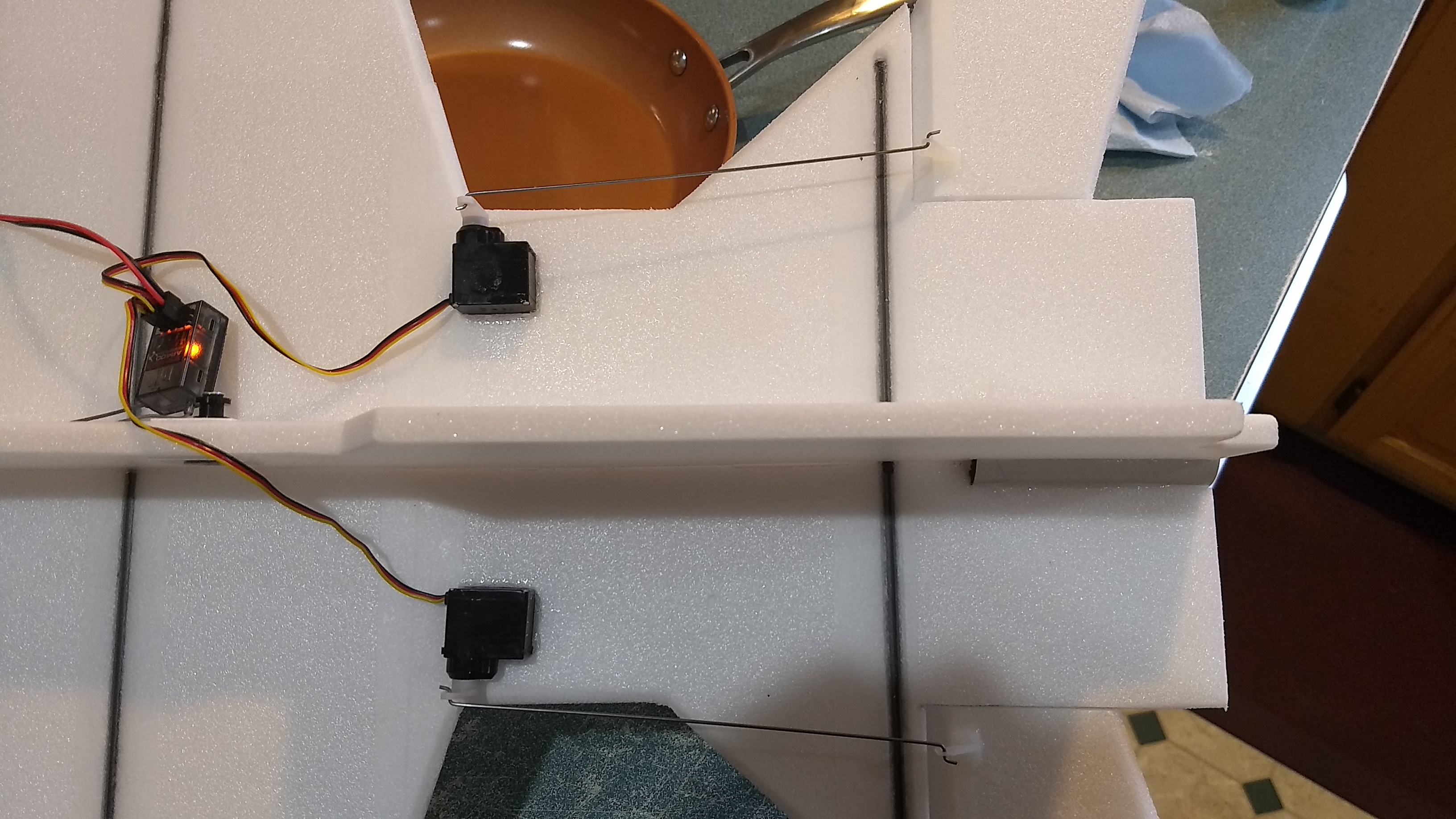
- glue the two servos in place making sure the control surfaces are centered and move in the correct direction.
-
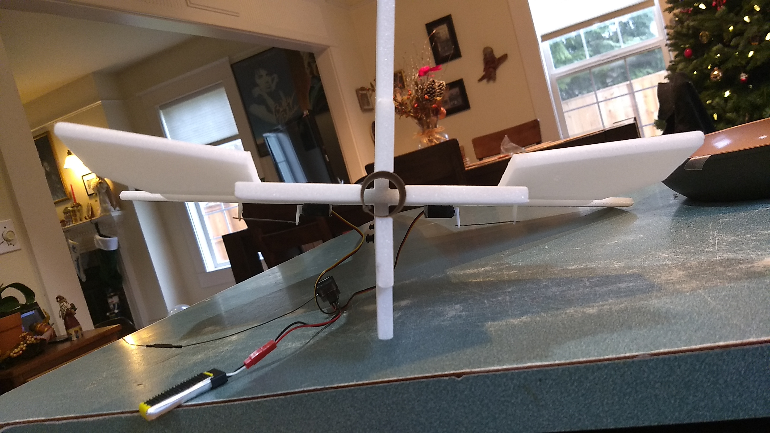
- Up elevator example.
-

- Down Elevator example
-
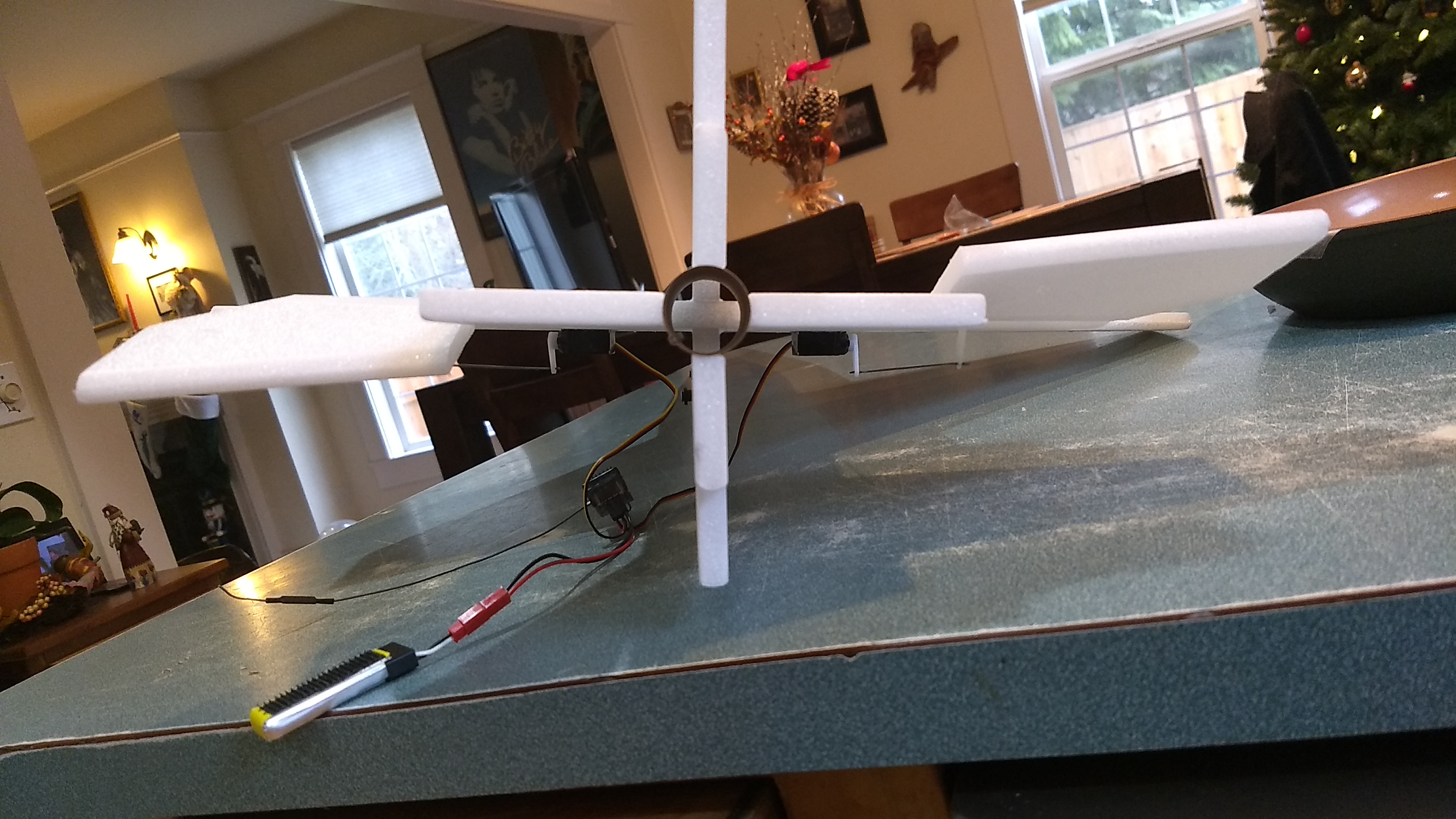
- Right Aileron example
-
- left aileron example
-

- Glide trim example.
-
- Route the servo wire on the rail button side through to the other side, tape down the wire and plug the hole in the foam.
-
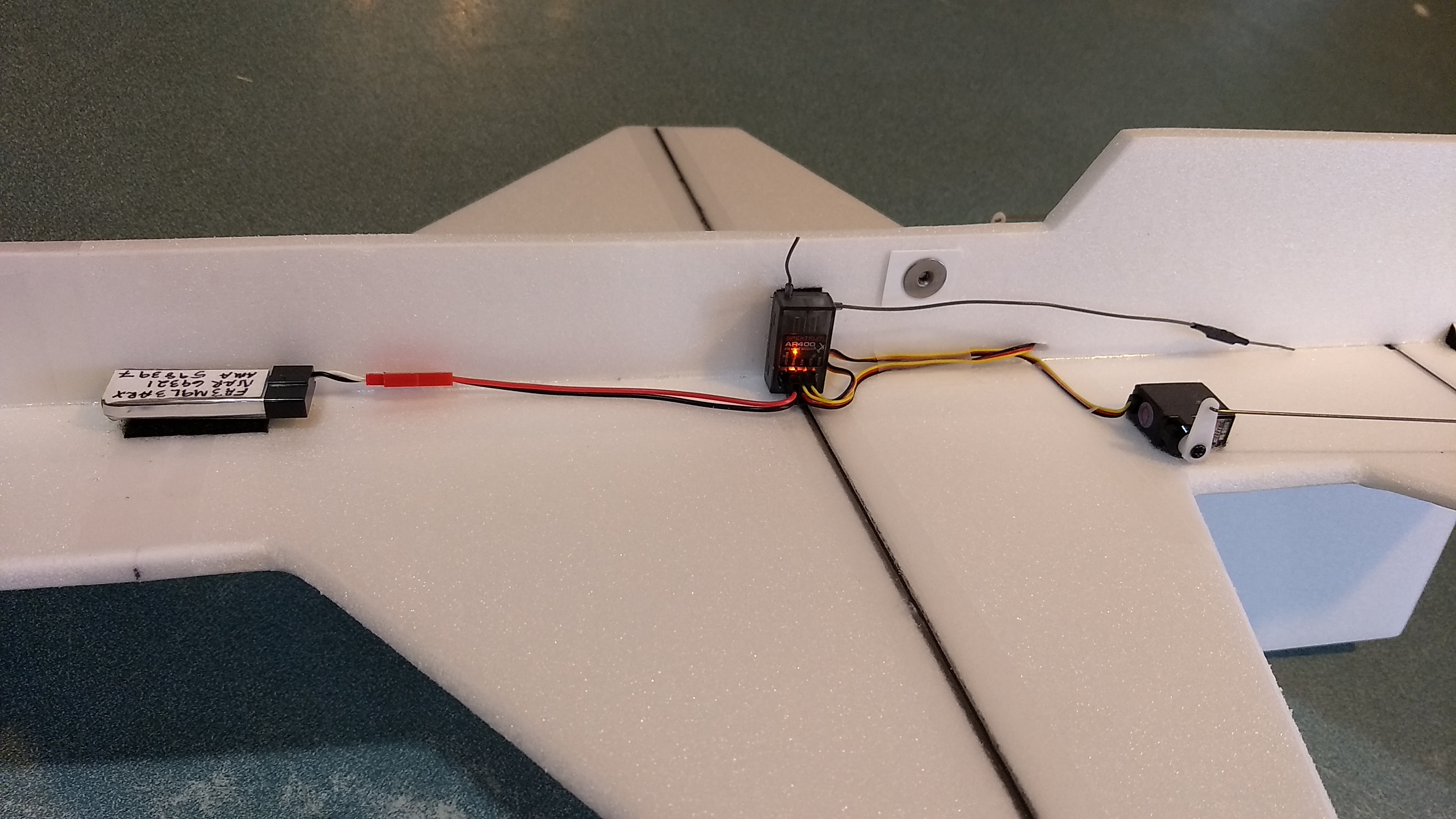
- Connect up the wire to the receiver, and tape down the other receiver wire and mount the receiver and battery on the side that doesn’t have the rail buttons.
-
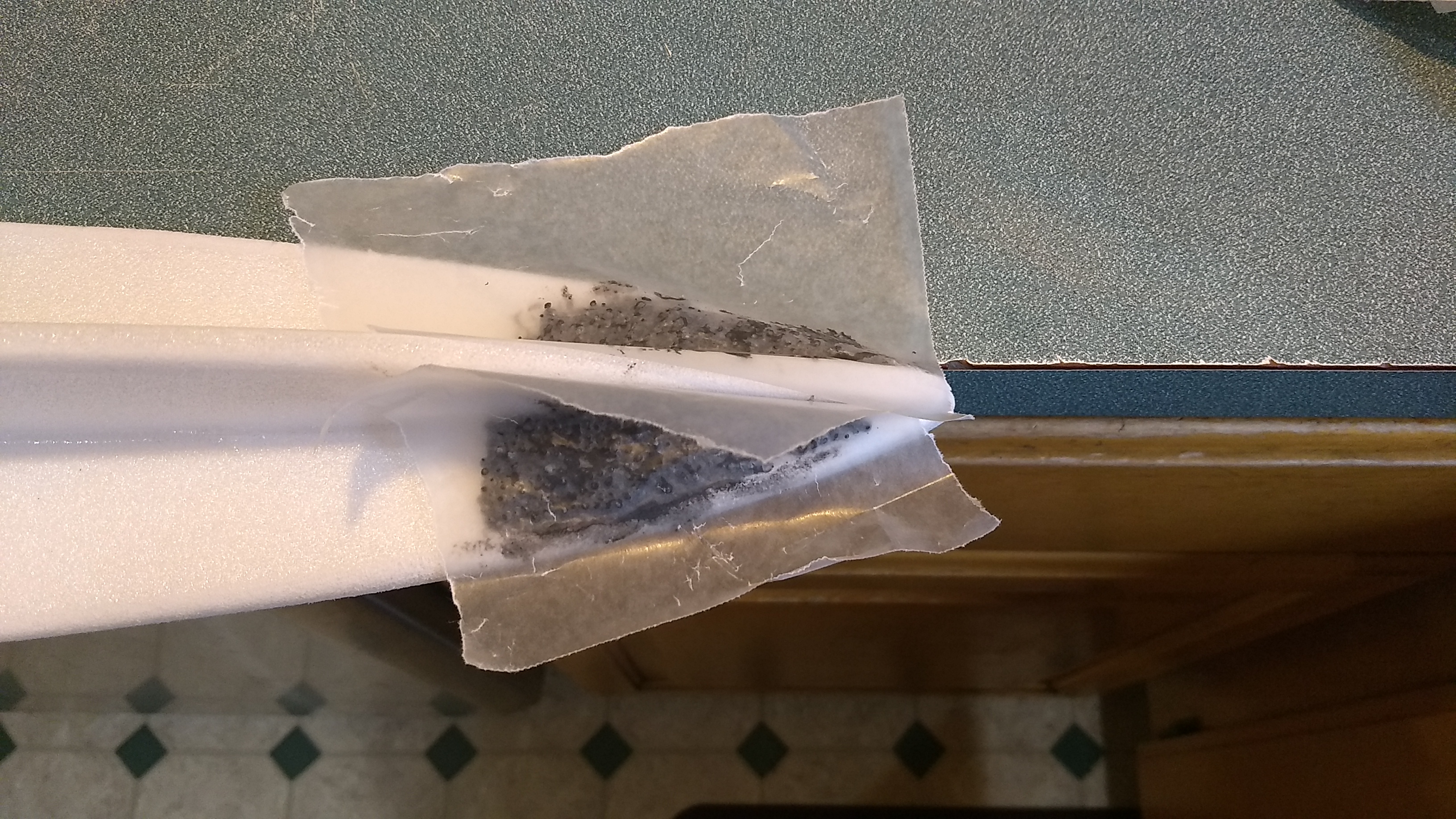
- Add nose weight, I used some wax paper to sort of press the lead around and shape it.
-

- Add extra lead with CA as needed to get a perfect balance.
-
- Panel lines added to top/bottom
-
- Panel lines added to side
-
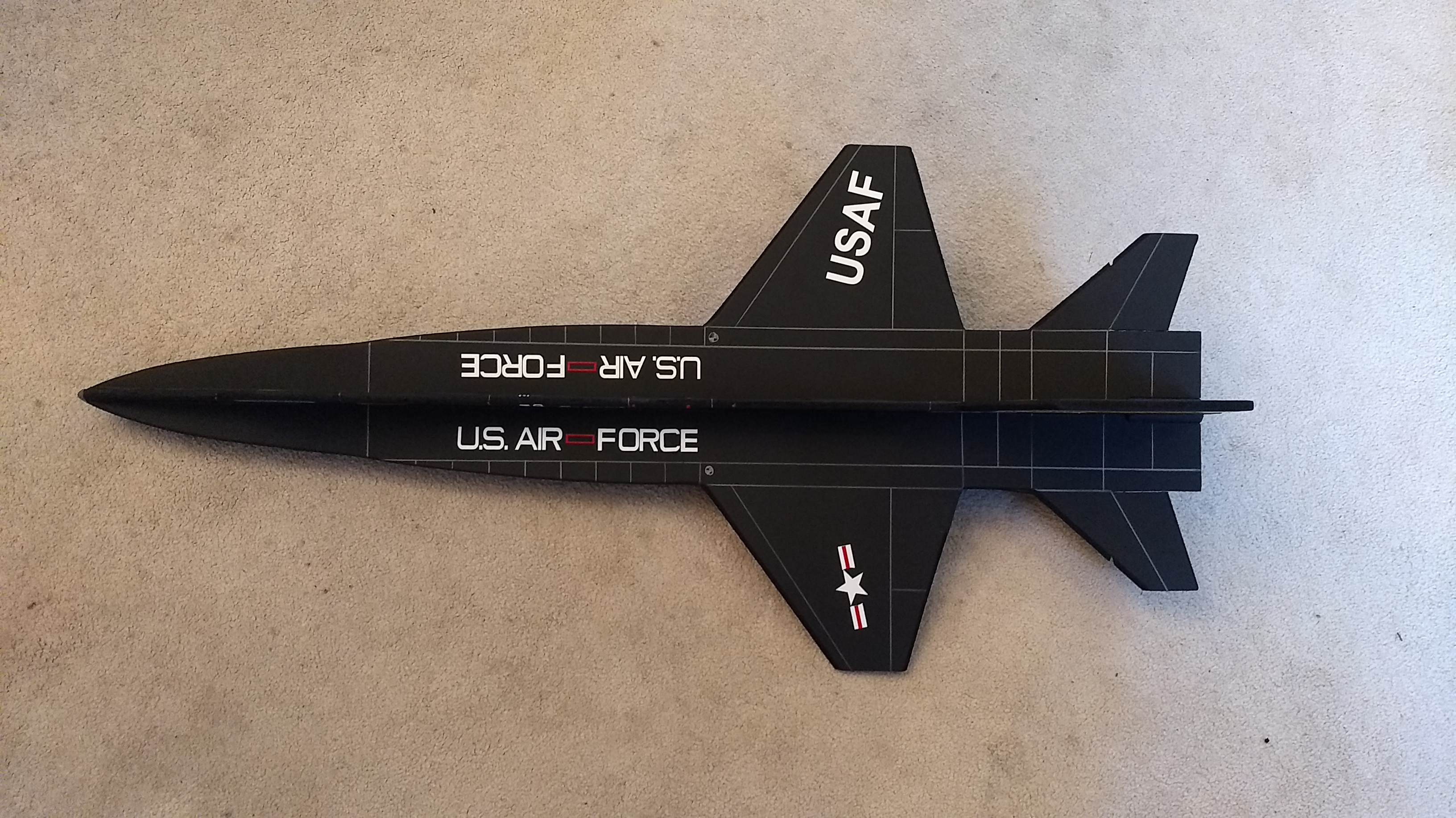
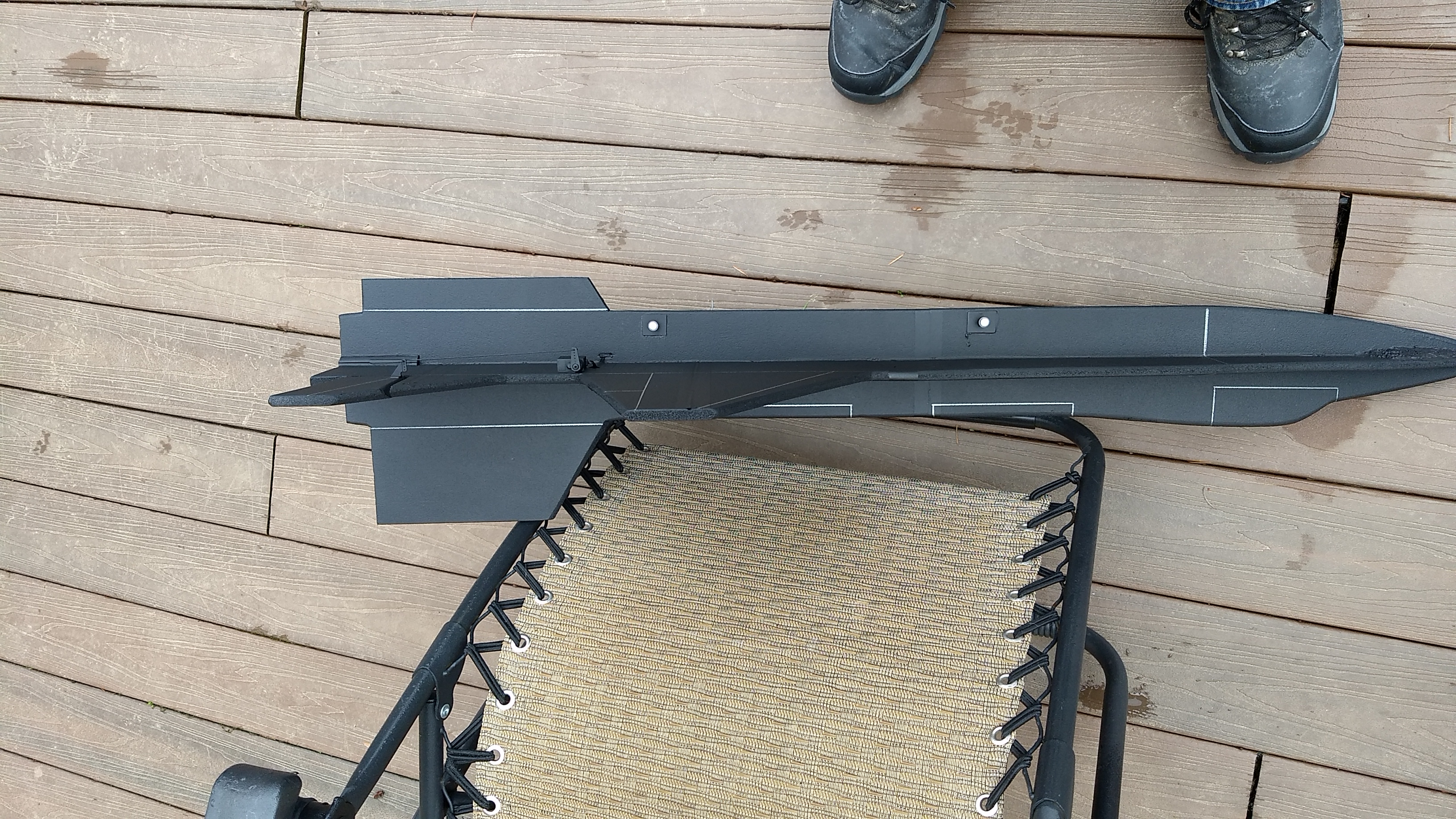
- Top view of markings
-
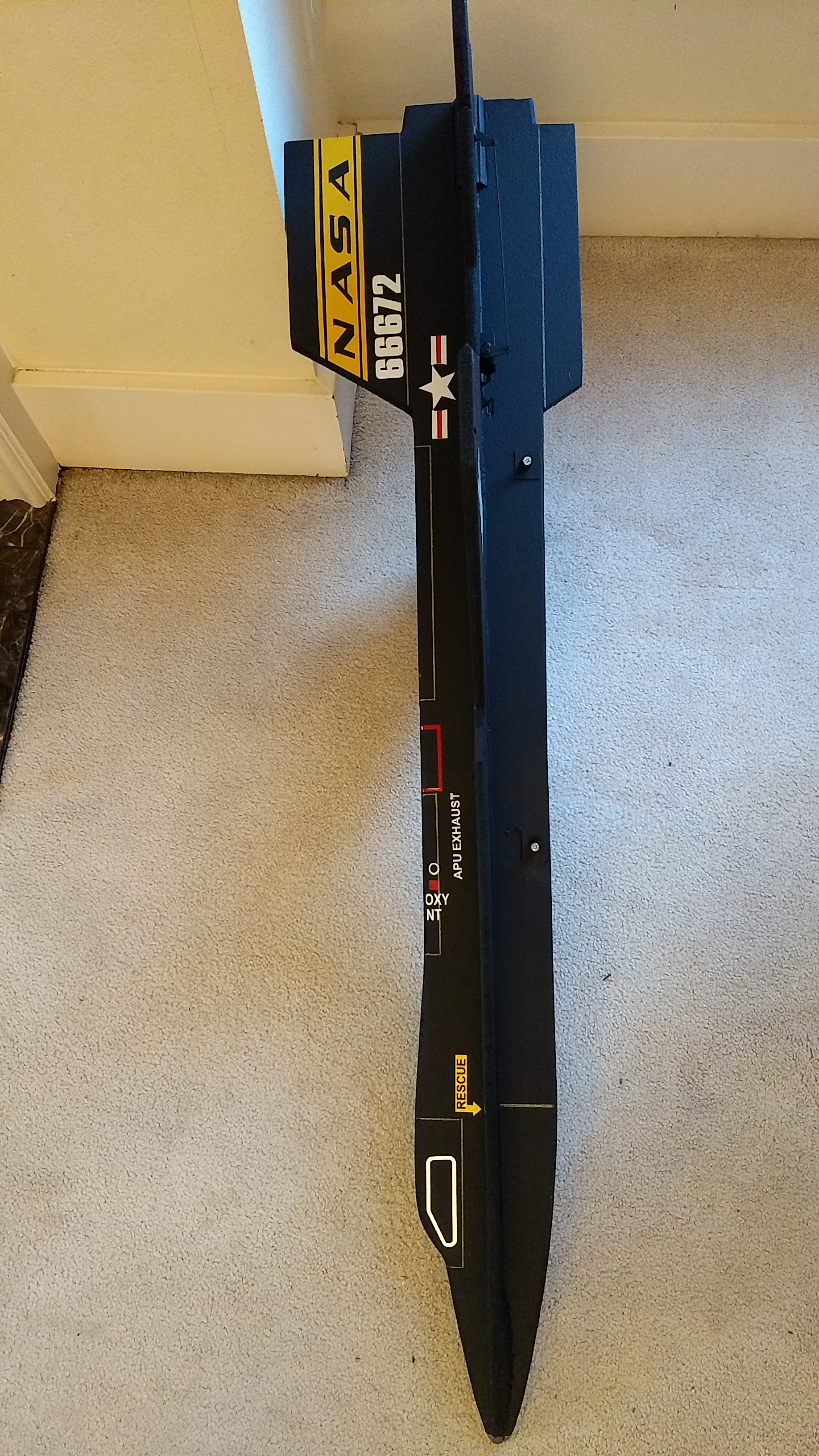
- Side view of Markings
-
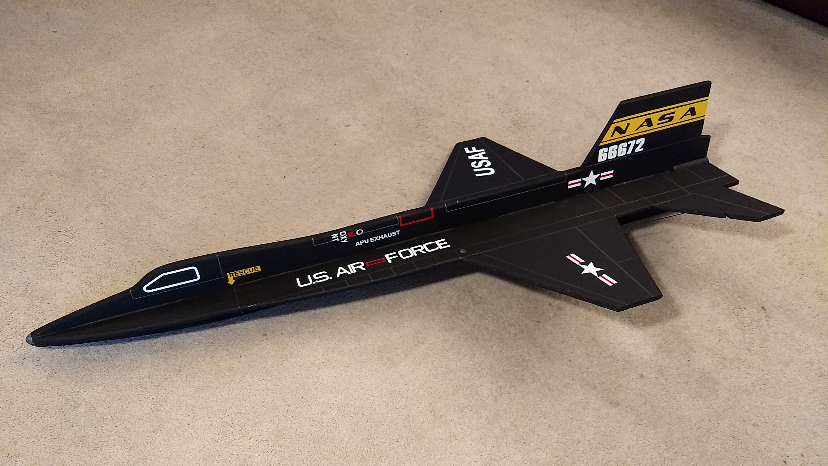
- Completed model