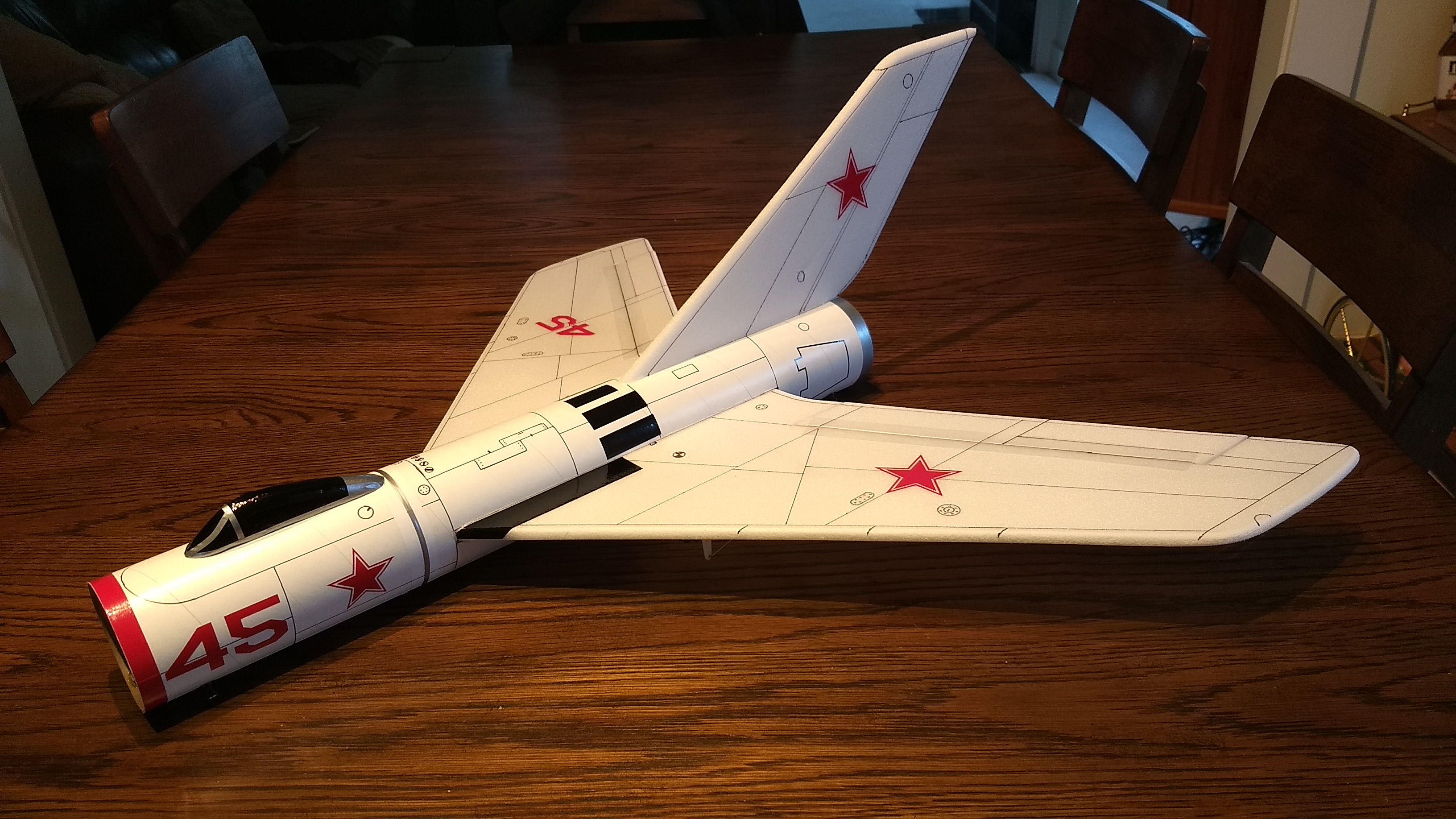
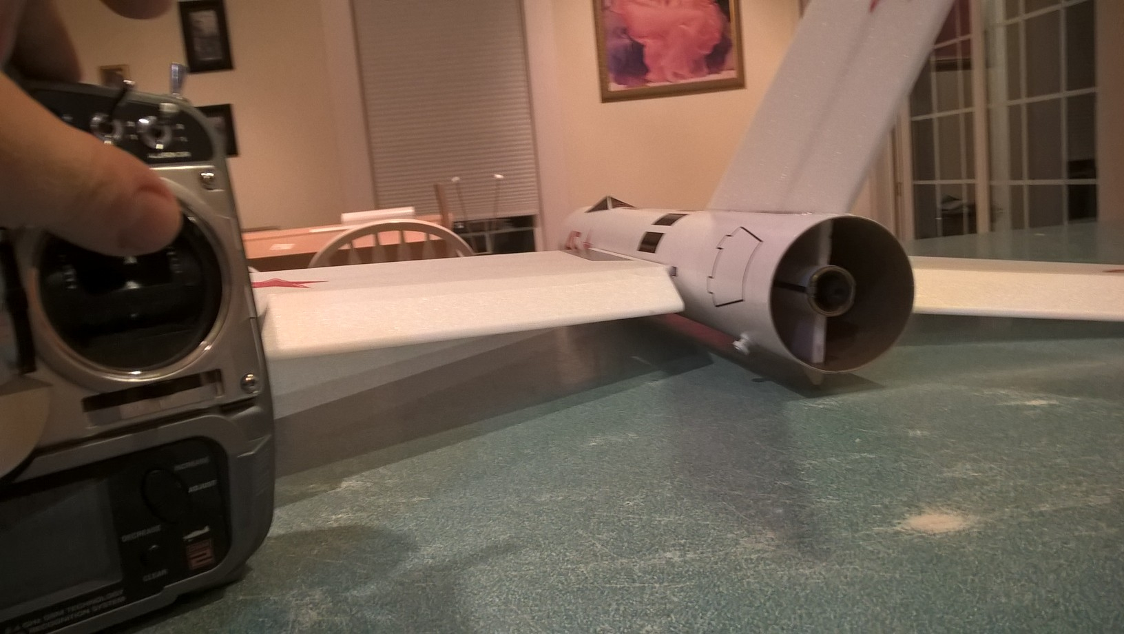
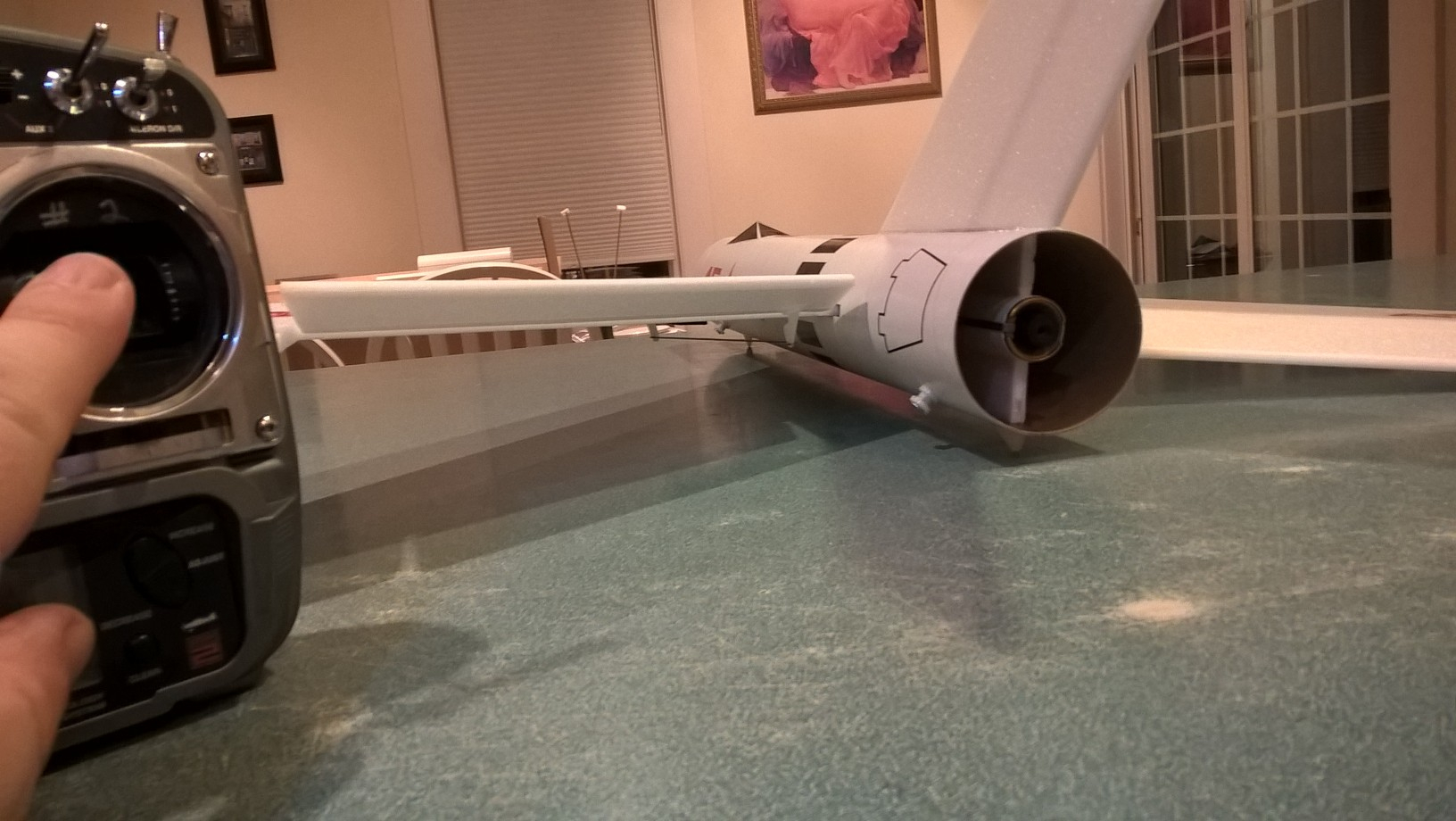
The Mig 10 RC Rocket glider kit is a cross between a Mig jet fighter and the old Centuri Mach 10 rocket glider. It comes with 3″ white tubing for the body, 9mm Depron wing and tail surface. Construction is very simple and takes about an hour and a half. Please refer to the General information for all kits tab above, then read these instructions completely before starting assembly. High Quality cut vinyl decals available HERE These instructions and decals also apply to the Wolverine kit which just had slightly different wing/tail shapes and a paper cockpit.
CG location for rocket flight should be 8.5″ forward of the rear of the body tube
Unpacking your kit:
The kits are packed to protect them in shipping, but the contents are fragile so unpack carefully. Carefully cut the tape holding the tubes in the box, then unwrap/lightly cut the plastic wrap to free the tubes, the spar may be packed in the tubes and the baggie with the little parts and nose cone will be in the tubes as well. Carefully cut the tape holding the cardboard wing protector in the box and carefully remove it, don’t pull hard or bend it. Then carefully cut the tape holding the cardboard top piece to the bottom. There may be some sticky tape holding the cardboard to the bottom cardboard piece, carefully peel it being sure not to bend anything. Once the top cardboard is free you can see the foam wing/tail parts, there are little fragile pieces in here, so unwrap carefully. It may be best to use an exacto to lightly cut the plastic wrap and carefully remove it without cutting into the foam. Make sure everything is free before you remove the pieces to avoid breaking anything. Kits contain one or two scrap pieces for repairs if you damage anything in construction or flight, just cut and patch in a spare piece of the foam if needed using foam safe CA+.
The 9mm depron used in this kit is different than the 6mm aero I use. It is much stiffer and stands easier and you need to go slow to avoid tearing as you sand. Also, the sheets have a nice side and a more bumpy side, I put the nice side up for the wings because that is what you see up close. This foam is the only thing like this that provides the right stiffness for this kit.
Welcome to the world of rocket boosted radio control gliders. This is not a model for a novice RC pilot, but anyone who is comfortable with RC flying of a medium speed model should be fine. Read through the instructions, look at the photos and be sure you understand the step before committing to cutting or glue.
Identify all pieces, the kit should contain:
1 wing taped together
1 carbon spar
Blenderm Tape
1 vertical stabilizer
2 control horns/Pushrods
3 canopy halves
1 Body Tube
Motor mount
2 1″ x 2.75″ wide strips to center the motor tube
Velcro(for battery and rx/bec attachment)
2 Rail buttons with t nuts/screws
Lead weight
Notes before starting:
Foam safe CA+, Bob smith super gold + is the only glue recommended for construction. You will also need foam safe accellerator to set the glue.
You may use 320 grit sandpaper and a sanding block to slightly round the edges of the foam if you prefer before gluing the wing and vertical stab in place. Do any sanding before assembly. Go slowly and use a sanding block, be careful as it is easy to have the edge of the block or paper catch the foam and tear a bit. After shaping I use a piece of 400 grit by hand to smooth it a bit.
Assembly:
- Unfold the wing and glue the tape joint using CA+ and accelerator, make sure it is flat.
- Test fit, then glue the spar in place in the slot on the bottom of the wing. Make sure to wipe any accellerator off then tape over the spar with blenderm tape once the glue has set. If there is tape left over, you can tape the center wing joint as well. Leave a little tape for taping down the servo wires after you install them.
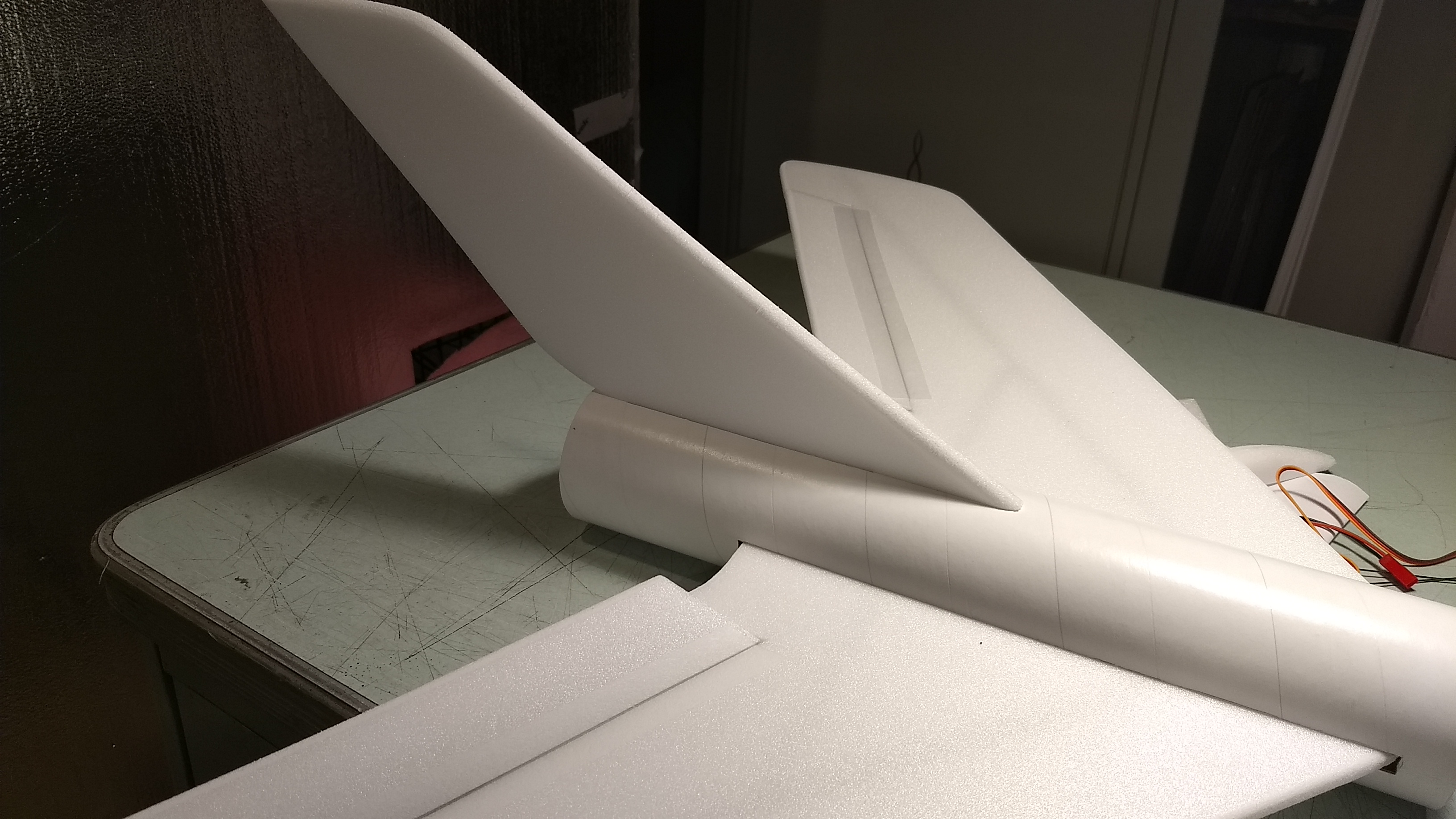
- Test fit the wing in the slot in the body tube. Sand the slot if needed for a good fit. The wing is inserted and then rotated into place, refer to pictures. Make sure the wing is centered. When satisfied, glue the wing to the body tube using foam safe CA+.
- Install the t nuts and rail buttons in the pre-made holes. The buttons are offset to the side so that they don’t get caught on anything when landing.
- Test fit the vertical fin in the slot, You may need to sand/trim bottom or the upper part of the fin to allow it to sit slightly lower and make full contact with the inside of the body tube.
- Apply glue to the bottom of the fin and glue it to the inside of the fuselage, make sure the fin is perpendicular to the wing. The fin fits into a slot cut into the rear of the wing which is also there to allow the wing to rotate into place.
- Apply a fillet of CA+ to the inside and outside of the tube/vertical fin joint.
- Glue the two motor centering strips onto the two opposite pencil lines on the motor tube. See photo.
- Test fit the motor mount into the rear of the body tube and into the slot in the vertical fin. Sand the tabs as necessary to allow it to fit. Push the motor mount into the fin until it seats fully, then glue the motor tube into the slot in the fin tab. Note the rear of the motor hook is allowed to move, make sure the taped portion is pointing forward. Then run a fillet of CA+ at the motor mount/fin joints.
- Glue the 2-3 canopy halves together depending on the look you want(wider or skinnier), then sand it round to a pleasing shape. Roll some sandpaper over the body tube and sand the bottom of the canopy bottom to a matching curve.
- Install the control horns/pushrods into the bottom of the elevons with CA+ in the pre-made holes. The pushrods should be on the inside of the control horn closest to the body tube. Make sure these are installed securely.
The basic construction is now complete.
Radio Installation
Note: Your radio needs to be configured for Delta mixing, this means that the servo arms will move the same direction during elevator stick movement and opposite for aileron stick movement. Connect your servos to the receiver one in the aileron connection and one on the elevator connection and apply power. Use a servo arm at least 9/16” long and with holes small enough that there won’t be slop with the pushrod wire when installed. I use the hole furthest out on the servo arm, to maximize movement. On some servos there are a long two-ended servo arm, you can trim off one end if needed to get sufficient length. Zero out any trim settings on the transmitter. The model once the motor has burned out is nose heavy and flying wings lose pitch authority when nose heavy so you want as much up elevator travel for trim/flare as possible.
- Connect a servo to each pushrod, the servo wire should be closest to the center and the output shaft is outboard toward the wing tip. If the wire is too tight, you can use twist an exacto knife in the servo arm hole to make it larger, but be careful and do not make it too large. Once connected, tape each servo in place so that the control surfaces are centered. Flip the model right side up and look at it from the rear. Moving the transmitter stick back(up elevator) should move both elevons up. Moving the transmitter stick to the right should move the right elevon up and the left elevon down. If you can’t get the servo reversing to give you the right polarity try swapping aileron/elevator inputs to the receiver or turning the servos over and swapping the servo arms to the other side of the output shaft. If that is correct, continue.
- Flip the model upside down and supported. The servos may be attached to the model using double back servo mounting tape(not included) or by directly gluing the servo to the wing with CA+ or a small amount of epoxy. Double back servo tape can loosen over time and with exposure to heat, I prefer to glue the servo in place. With the radio still on, put a small amount of glue on the servo, being careful not to get any near the output shaft. And set it in place on the model keeping the control surface centered. Do the same to the other side. Make sure the glue is set before continuing. The servo and pushrod should be at 90 degrees to the hinge line so that it moves easily and fully. The servo should not be glued to the blenderm tape as it won’t adhere well. You can move the servo slightly left or right to avoid the tape.
- Flip the model back right side up. Make sure the control surfaces are centered, use trims if needed. Now measure the control surface movement. Full elevator movement should be 3/4” in each direction, aileron movement should be 1/2″ in either direction. Since the model will be nose heavy, elevator elevon movement helps to give sufficient authority during glide.
- If you have a flap/elevator mix you can program up elevator to a switch setting. The model needs approximately 1/4” of UP elevon during glide and 1/16″ or less DOWN trim for boost. If you can’t set the up elevator trim to a switch on your radio you’ll have to manually put in glide trim which is hard to do while flying the model. (On my spectrum dx8 using hs65hb servos, 100% aileron and 125% elevator dual rate settings, the elevator flap setting was -6 for boost and +32 for glide.)
- Attach a 12″ servo extension to each servo so the servo leads come out the front of the body tube so you can hook them to the receiver.
- Make a slot in the bottom side of the fuselage on each side and pass the servo wires through to the inside and toward the front.
- Attach the servo wires to the receiver and make sure they are going the right direction. Tape down the servo wires to the wing to secure them.
- Use the included Velcro to attach the receiver and battery to the model at the front inside bottom of the body tube. This allows you to be able to remove and replace the receiver if needed for repairs or for removing the servo wires.
- Insert your heaviest loaded rocket motor into the motor mount
- Support the model upside down at the balance point indicated for boost. I use two pencils with the eraser pointed up and held in place with a small hand vice. Place the midel on the pencil erasers on the balance point indicated above. If necessary glue some of the lead weight at the front or rear of the model to balance it as needed.
- Do not try to fly the model with it balancing it behind this point. The adage is, a nose heavy model flies poorly, a tail heavy model flies once.
- Use a black sharpie to add panel lines if desired. I also used a silver sharpie to add some extra details, cockpit window outline. Keep in mind that paint adds weight, it’s better to leave it unpainted for best performance. Refer to the general instructions for paint restrictions. I also added a strip of 2″ wide packing tape onto the bottom of the fuselage to prevent the tube from getting wet/dirty on landings.
- Re-install the receiver and battery
Flying: See the Instruction/Information link at the top for flying instructions Note this model uses a slight down trim for boost unlike the other models which use neutral controls for boost. Be ready on the first few flights to keep the model straight till you have the trims set perfectly.
-
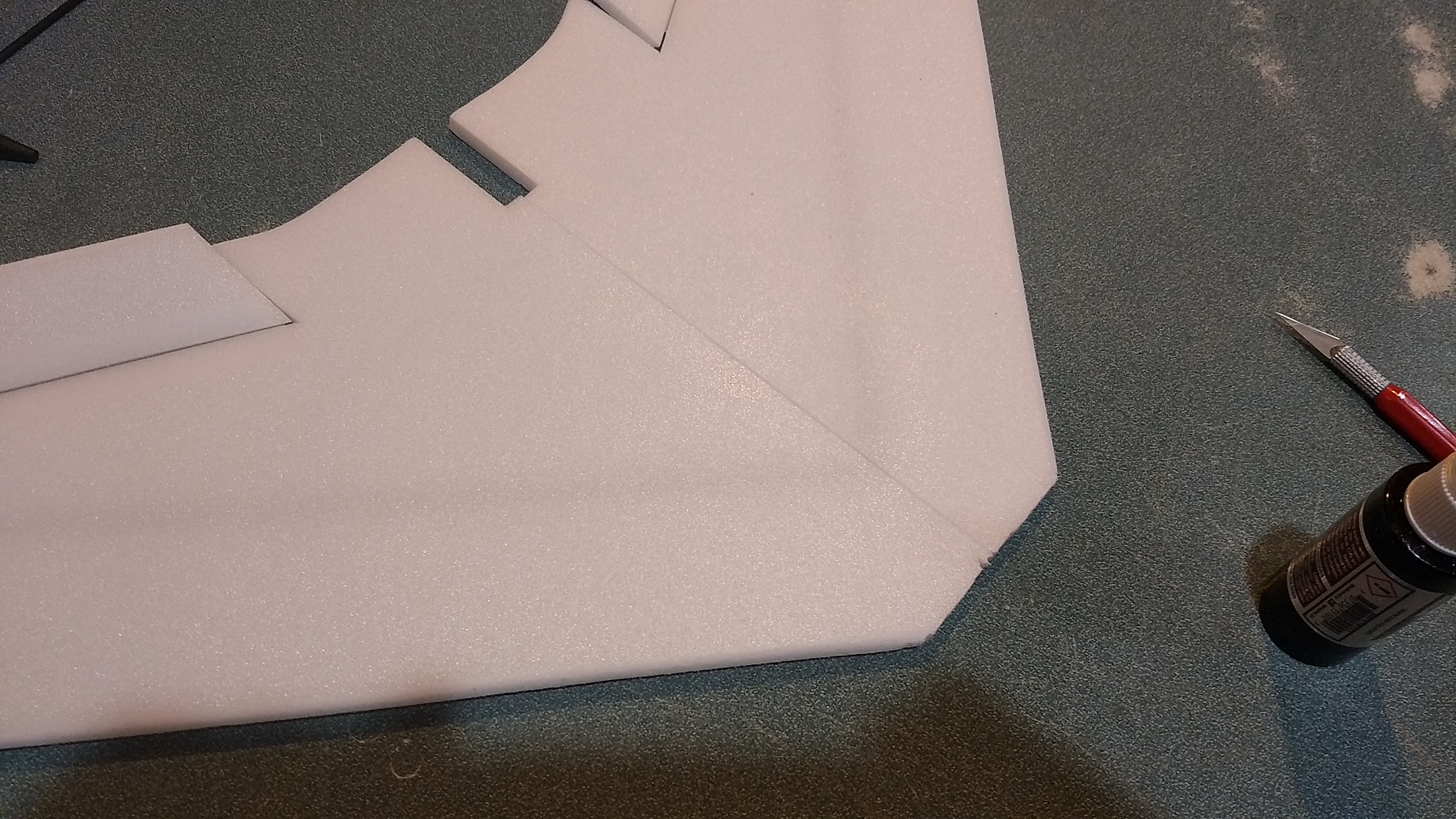
- Glue the taped wing center joint
-
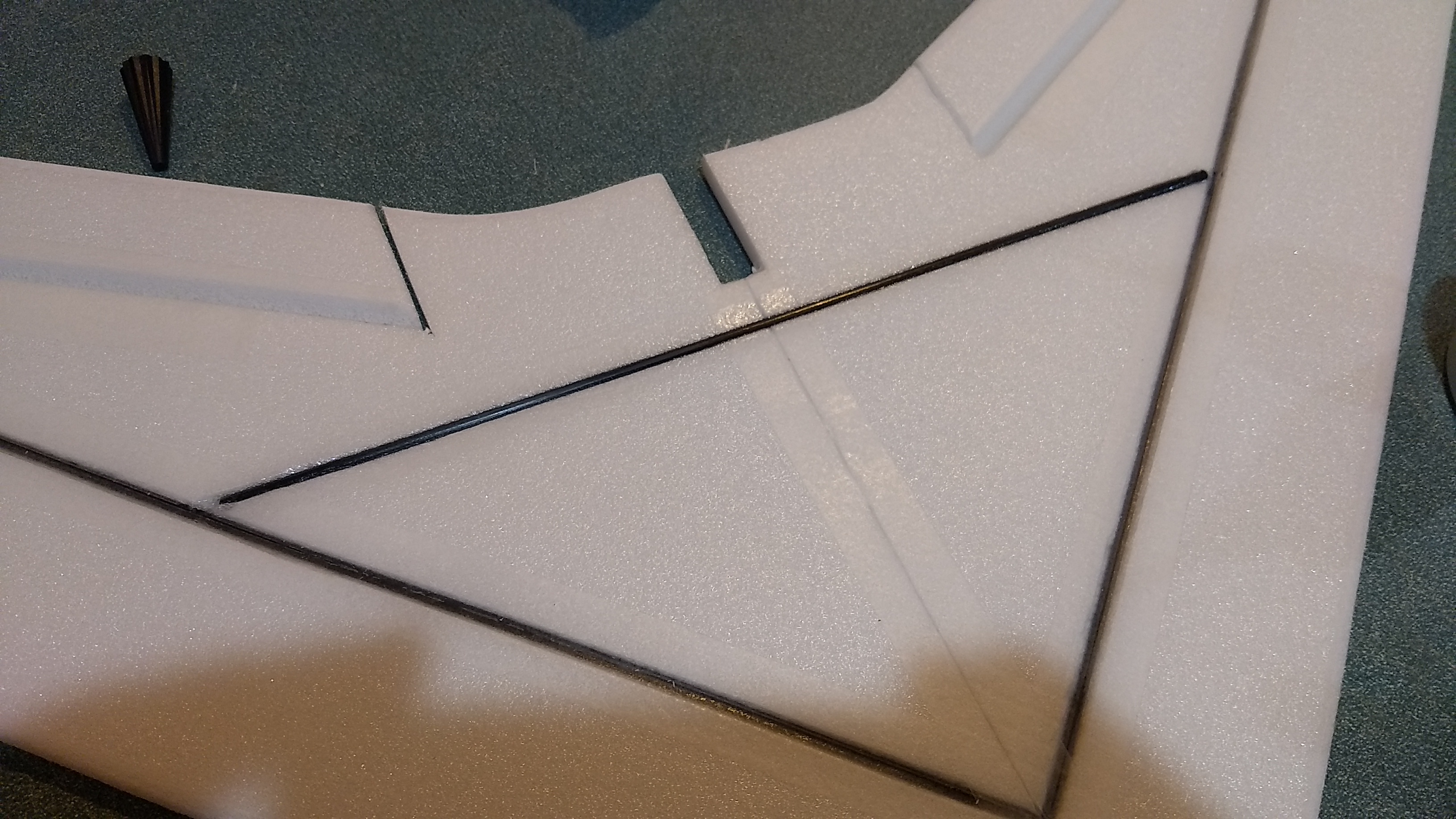
- Glue the cross spar in place
-
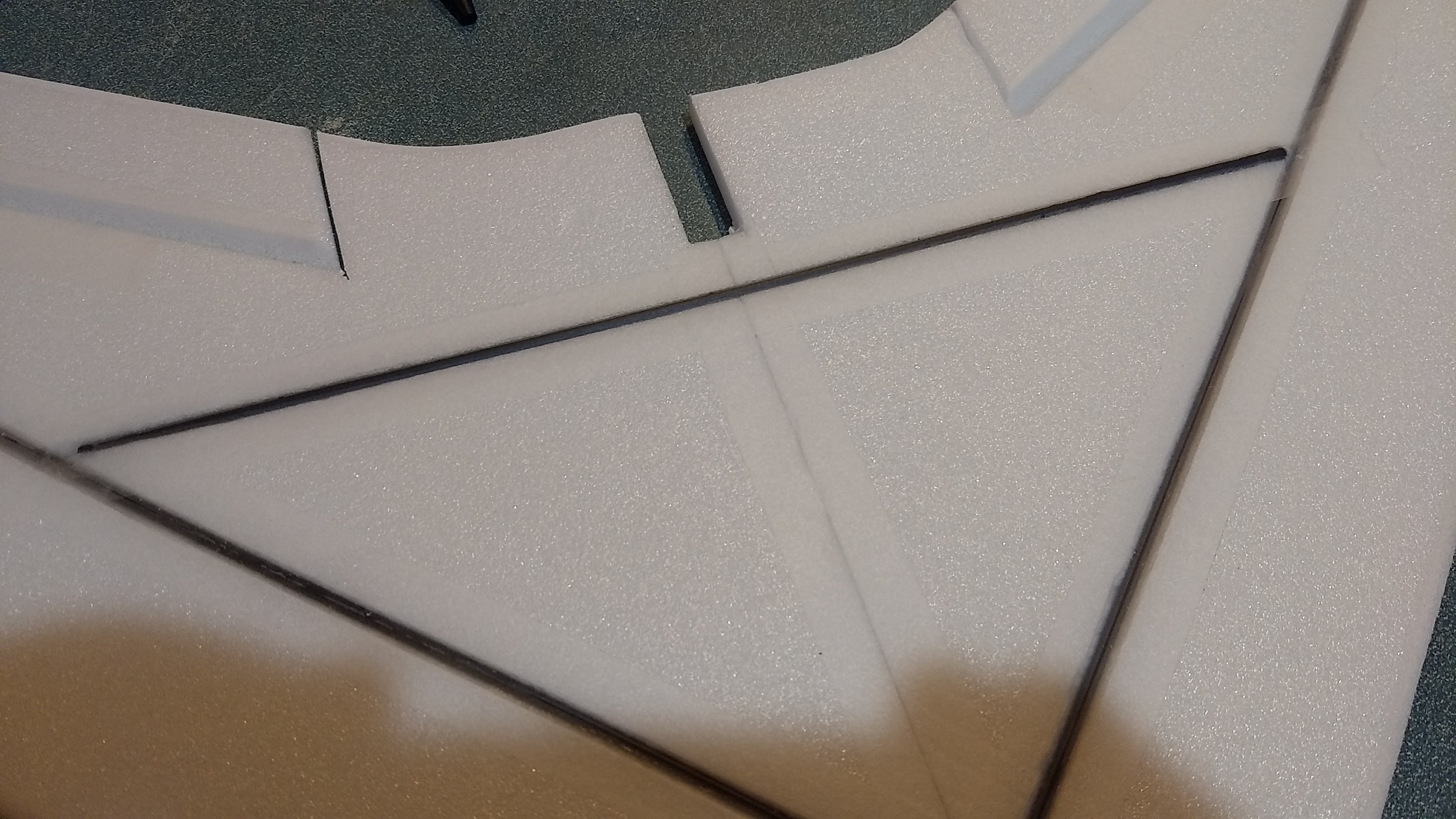
- Tape over the cross spar and then the center joint.

-
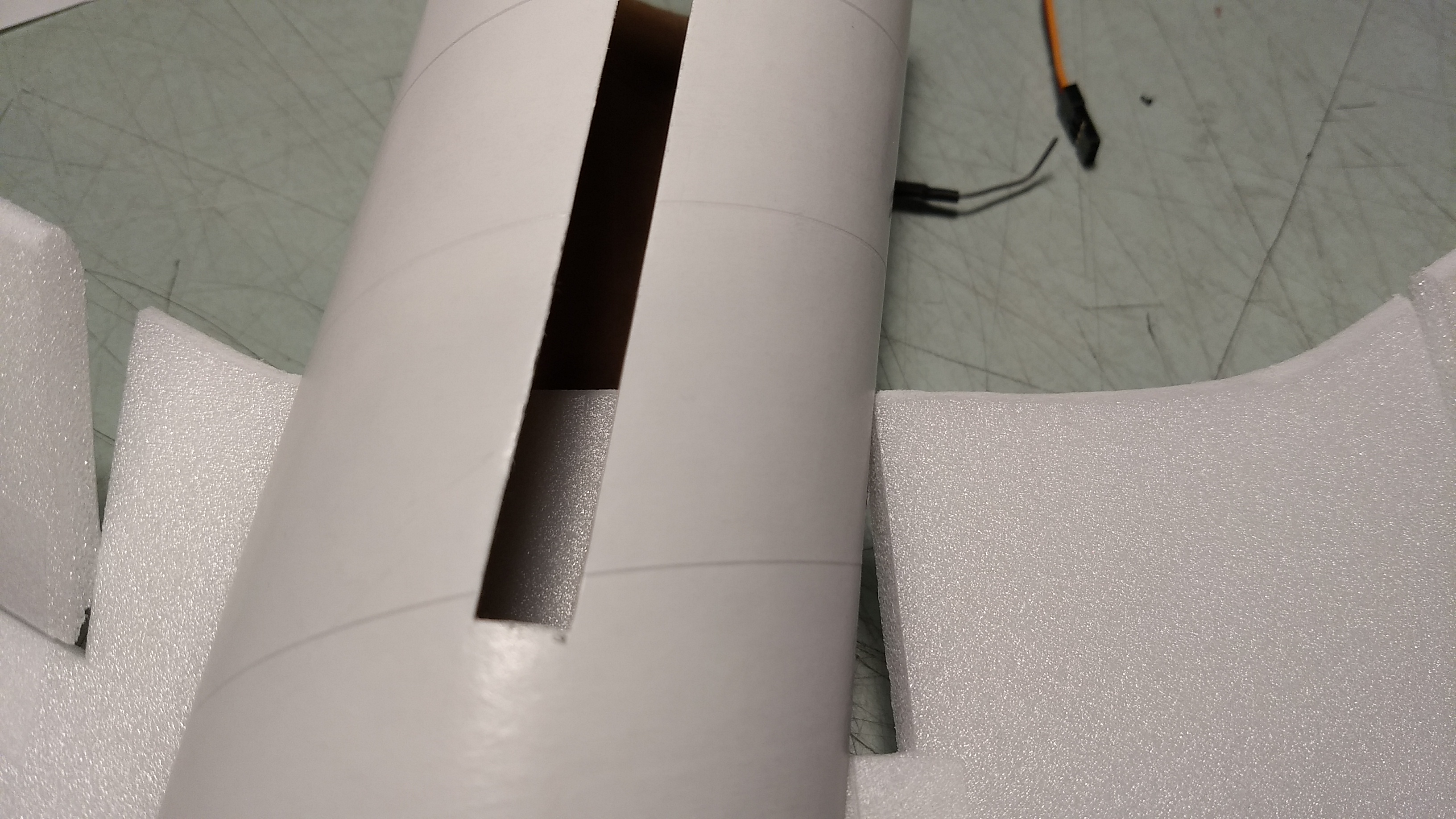
- Make sure the wing is inserted till the cutout in the rear center of the wing is against the wing slot
-
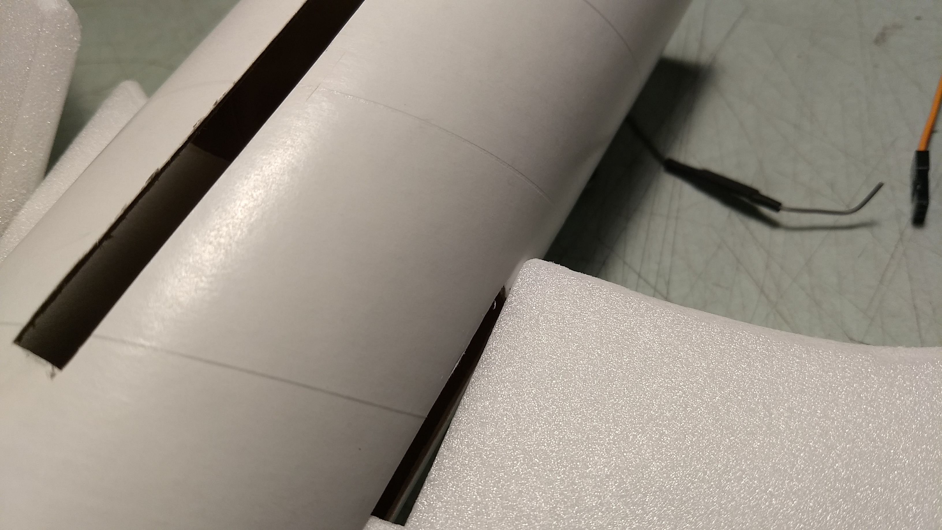
- slide the cutout in the wing back slightly till front clears slot
-
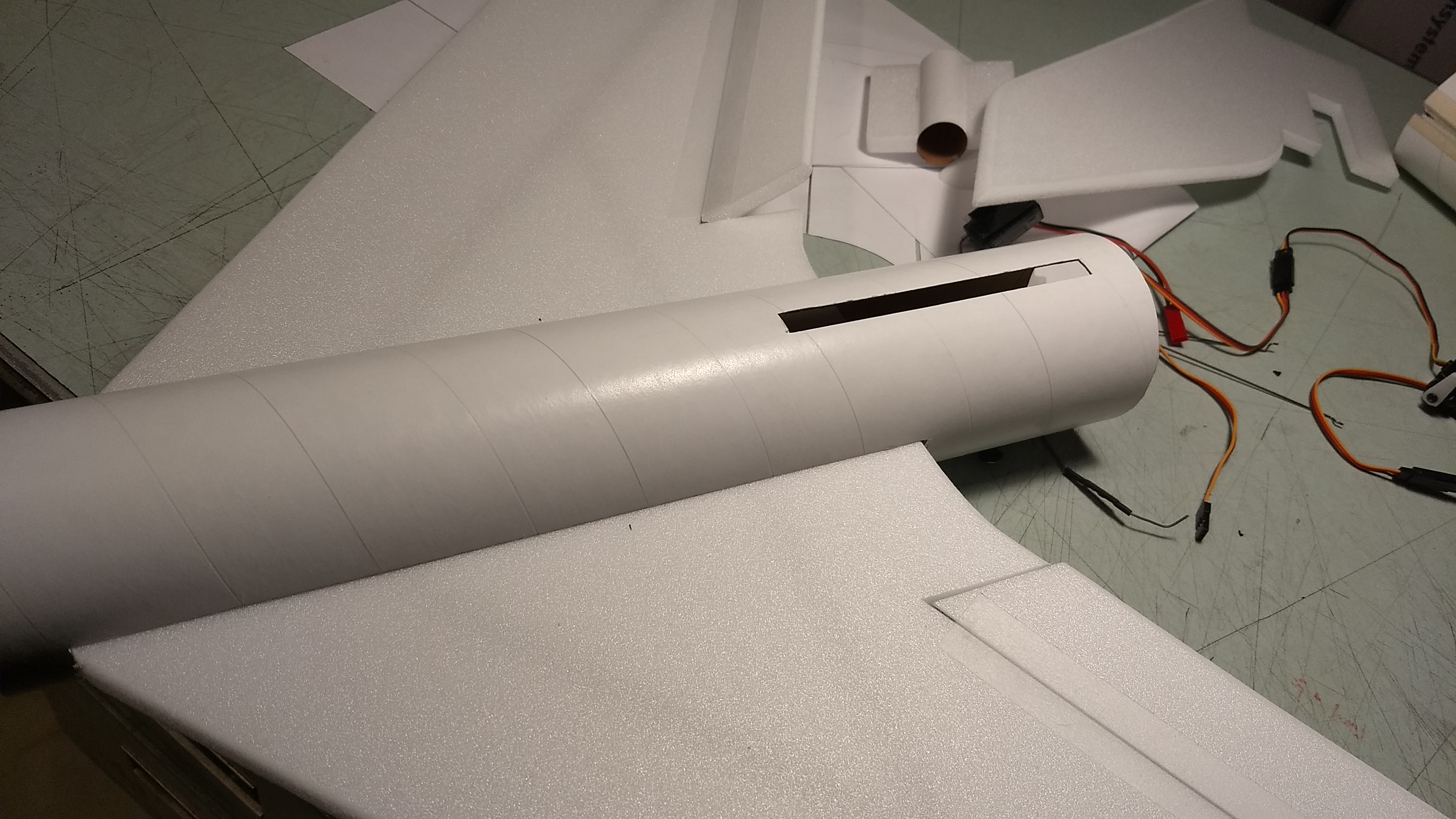
- rotate wing around and continue pushing it in sideways till it is centered, then glue in place
-
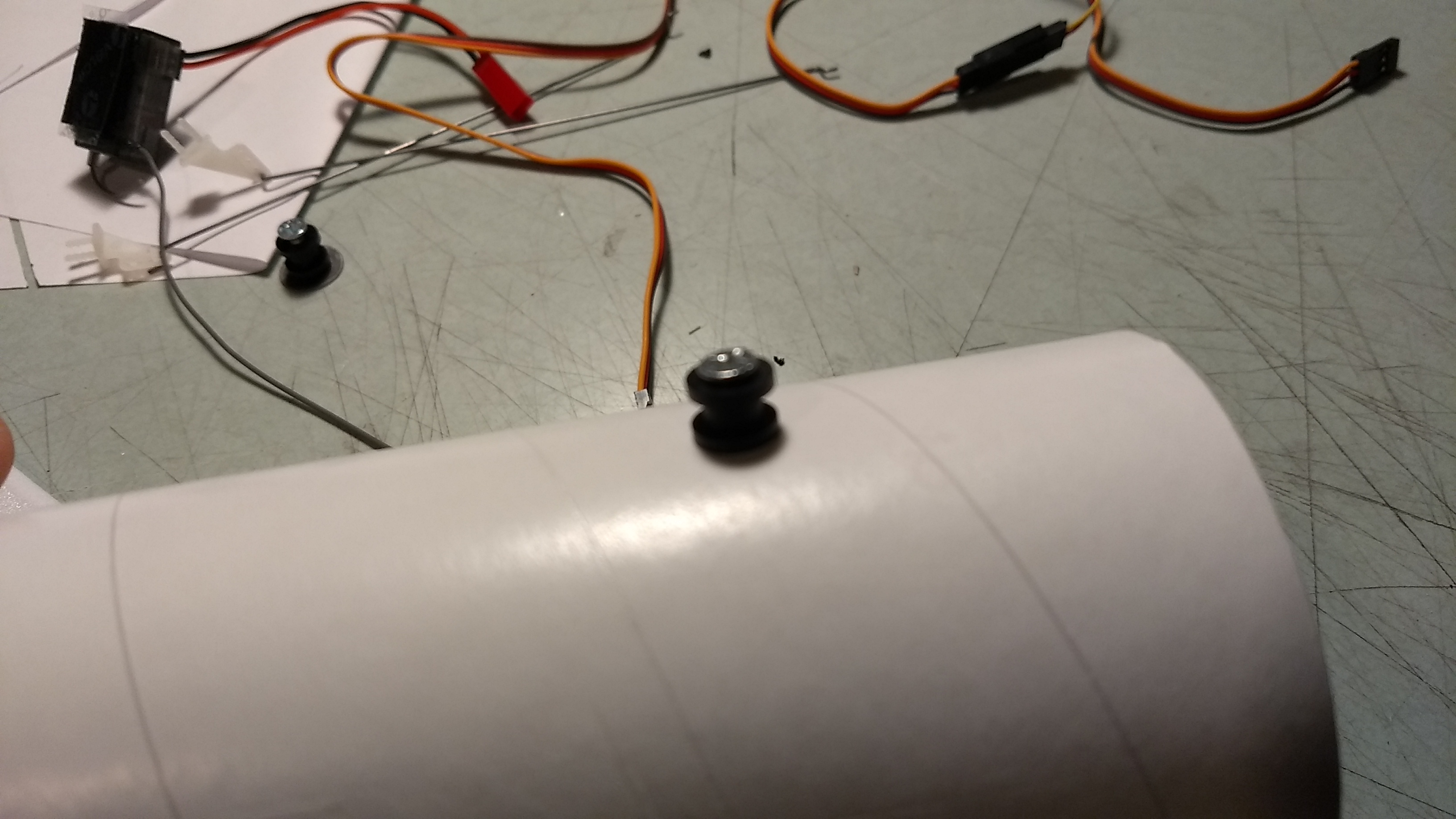
- Install rail buttons
-
- Test fit, then glue in the vertical stab.
-
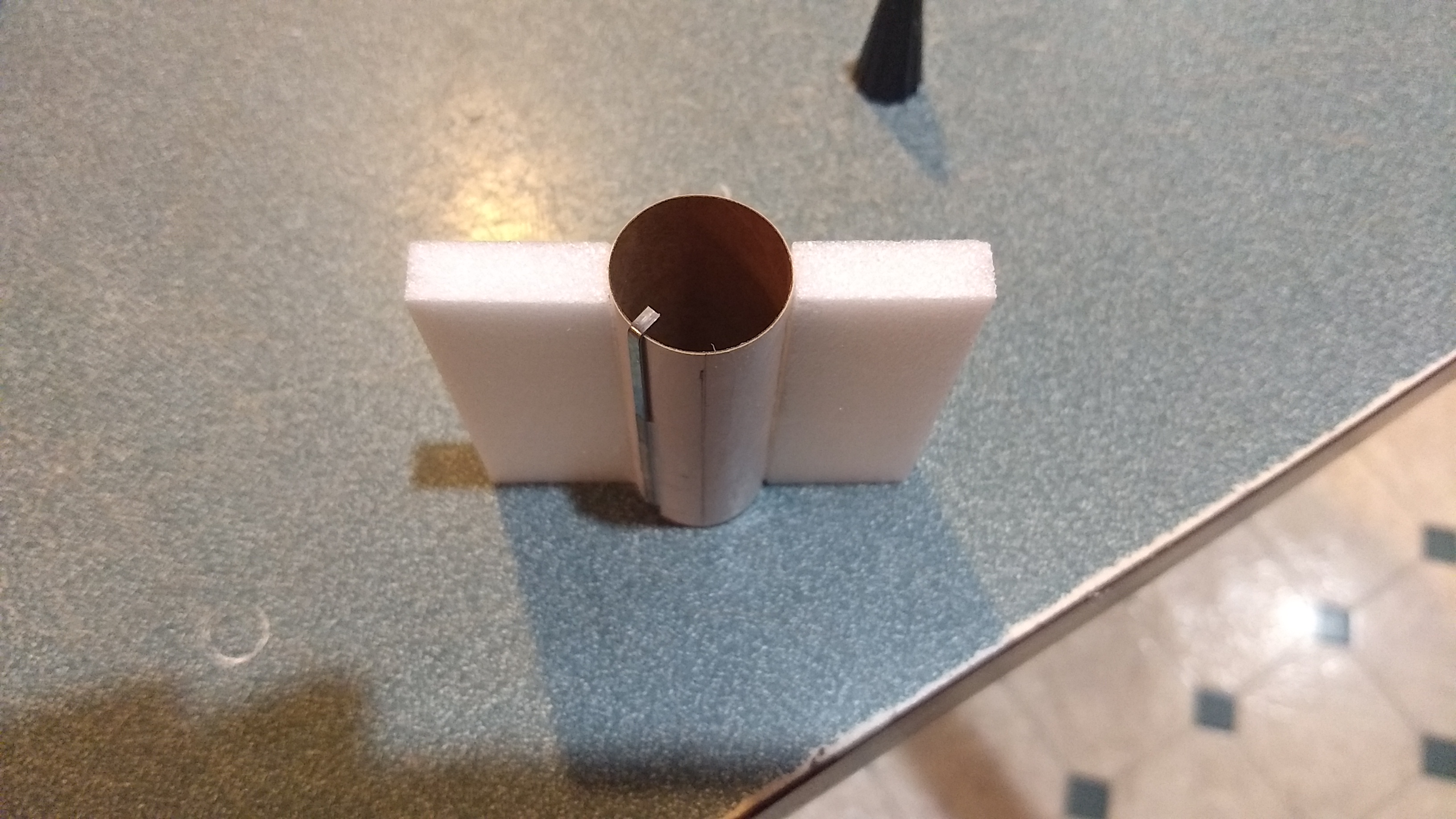
- glue the two foam centering strips on the two opposite pencil lines
-

- Test fit and sand as needed to allow the motor mount to fit into the body tube and fin slot
-

- Insert the motor mount fully with the two centering strips horizontal, and glue in place.
-
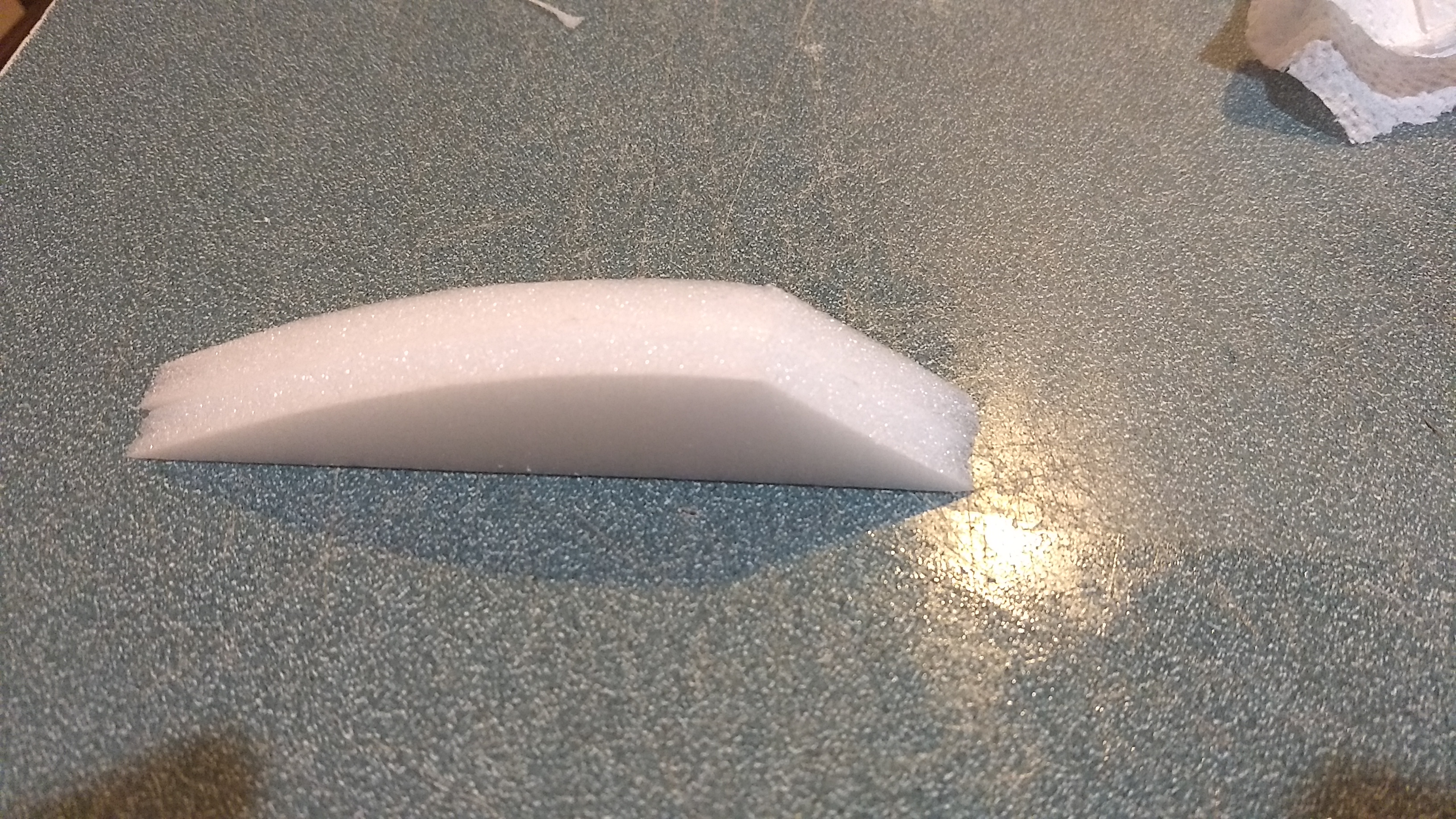
- Glue canopy halves together
-
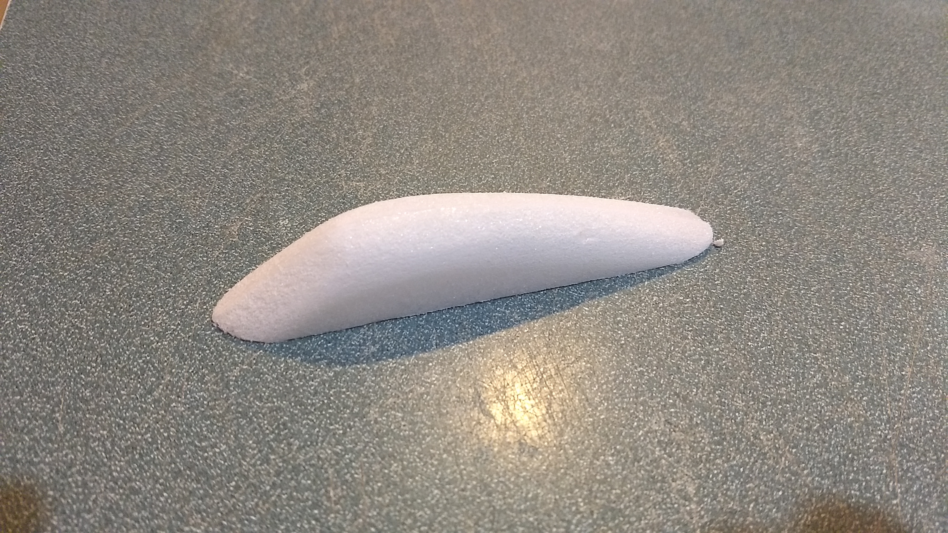
- sand the canopy to shape
-
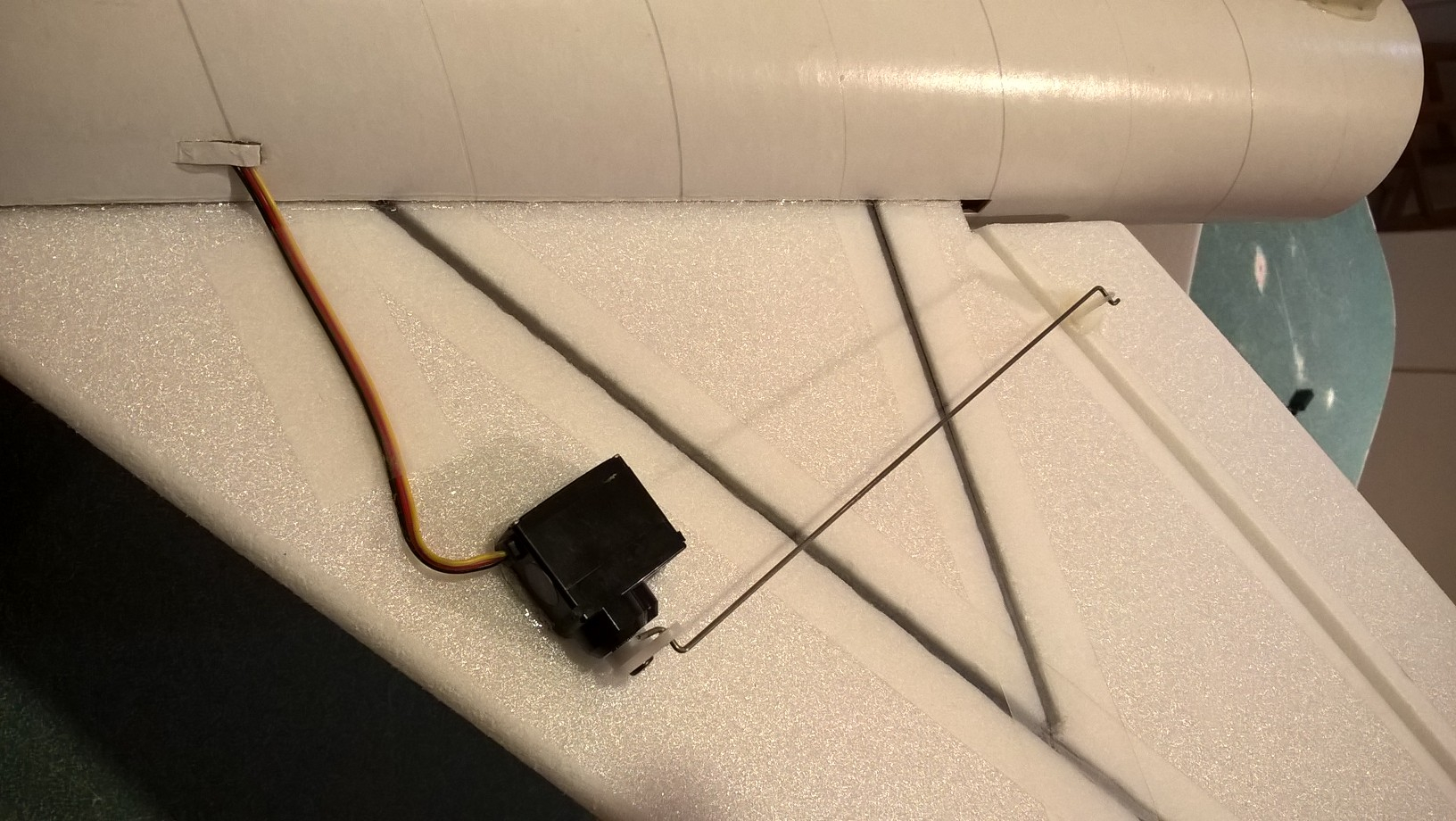
- Servo glued in place.
-

- Route the servo wires into each side of the body tube and tape in place.
-
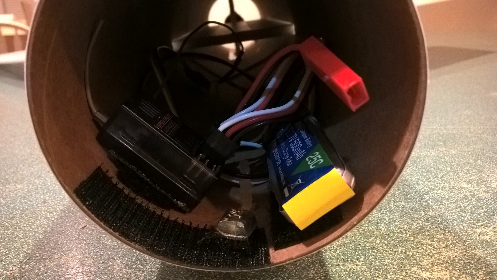
- Receiver and battery mounted in the front of the body tube.
-

- Balancing model
-

- up elevator
-
- Down elevator
-
- Left aileron
-
- Right aileron
-
- glide trim
-
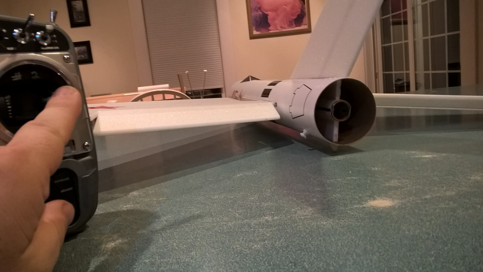
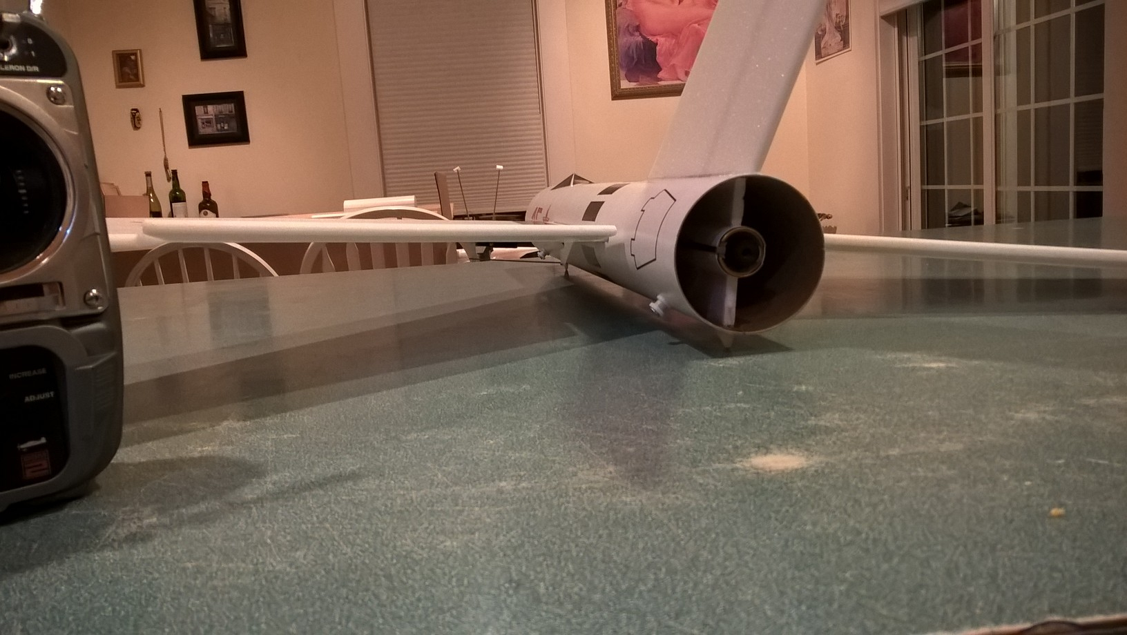
- Completed model