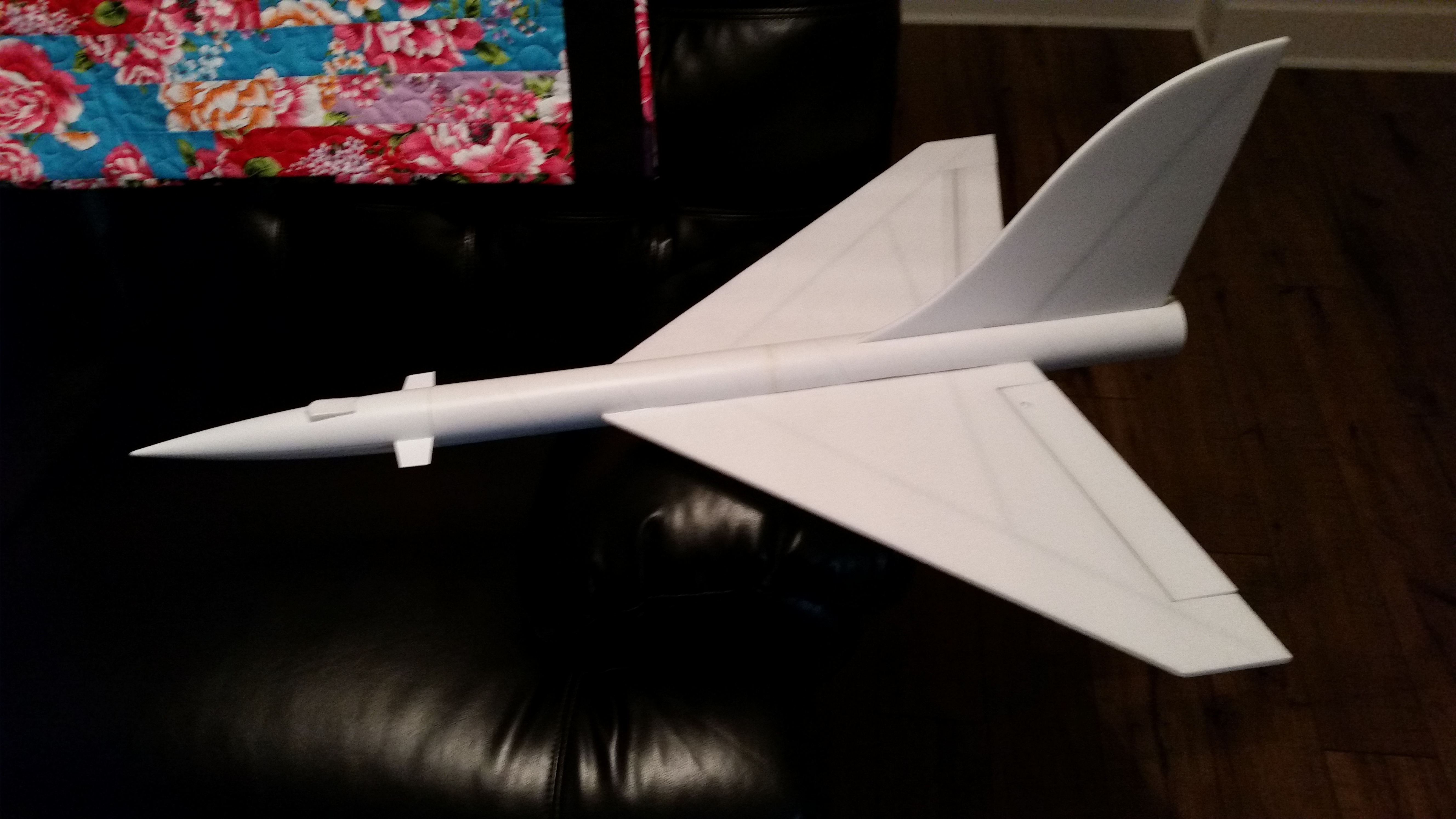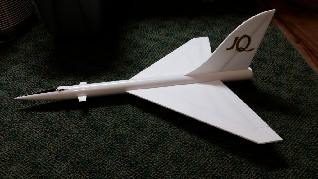
The Dragonfly RC Rocket glider kit is based on the Johnny Quest Dragonfly III. It comes with a plastic nose cone, 2″ white tubing for the body and Model Plane Foam (MPF) wing and tail surfaces. Construction is very simple and takes about an hour and a half. The only hard part on this model is cutting the slot for the wing after you assemble the body tubes, however the slot locations are pre-marked for you. You will need two 10 gram type servos, two 6-12″ servo extensions, a receiver, and a small 500mah single cell lipo battery. You will need a transmitter with delta or elevon mixing. You will need foam safe CA+. Please refer to the General information for all kits tab above, then read these instructions completely before starting assembly. CG location for rocket flight: 12” forward of the rear end of the body tube. This will be approx 1.5″ to the rear of the joint between the two body tubes.
Welcome to the world of rocket boosted radio control gliders. This is not a model for a novice RC pilot, but anyone who is comfortable with RC flying of a medium speed model should be fine. Read through the instructions, look at the photos and be sure you understand the step before commiting to cutting or glue.
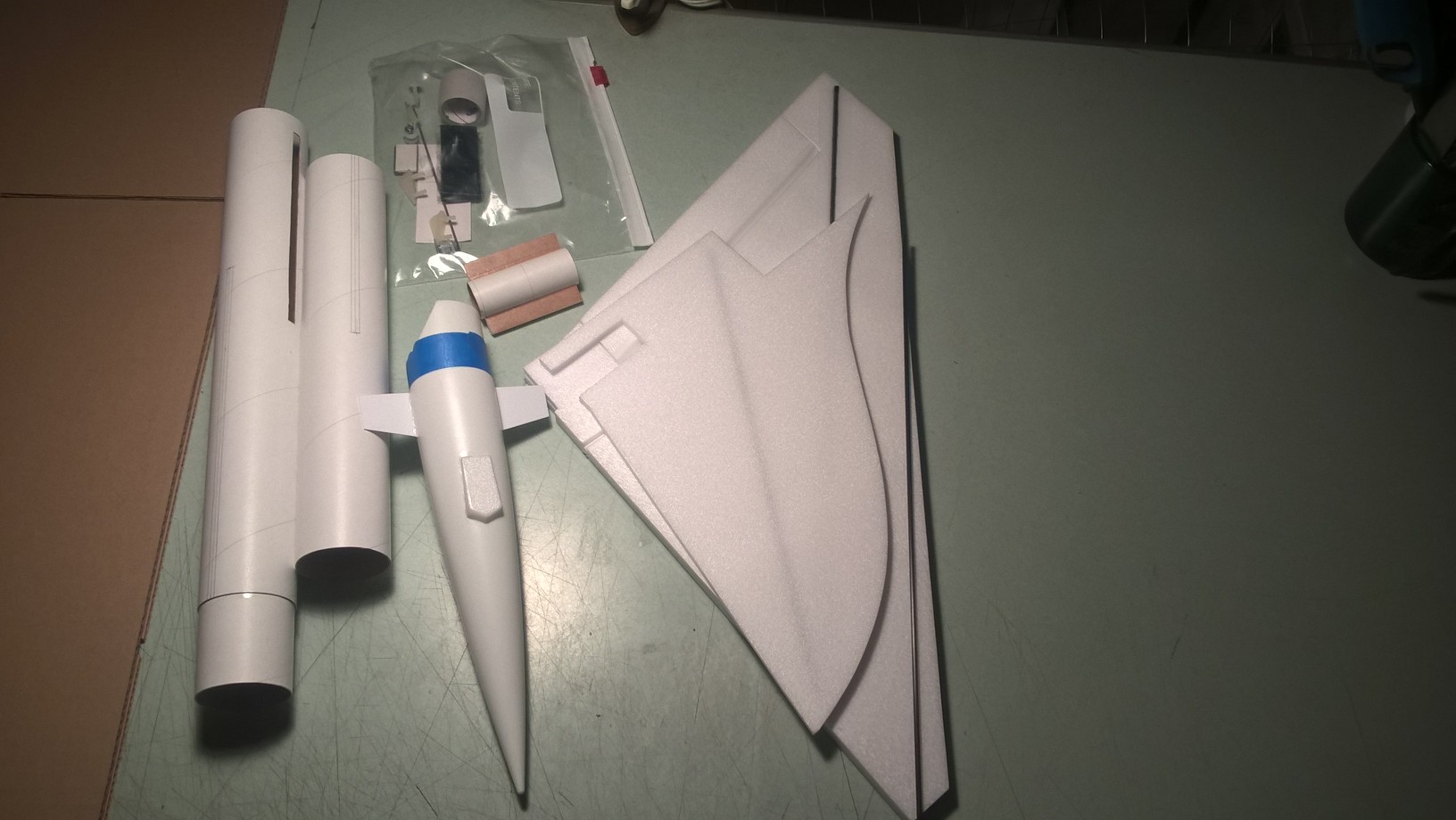
Identify all pieces, the kit should contain:
1 wing taped together
2 2.5″ long foam strips
1 Nose Cone
1 wing spar(carbon fiber)
2 pushrods
1 vertical stabilizer
2 control horns
2 Body Tubes
Motor mount
Velcro(for battery and rx/bec attachment)
2 Rail buttons with t nuts/screws
2 landing skids
3M blenderm tape
Lead weight
Spare foam (for testing paint, glue, and sanding the edges to see how it behaves)
Notes before starting:
You may use 220-320 grit sandpaper and a sanding block to slightly round the edges of the foam if you prefer before gluing the wing and vertical stab in place. Do any sanding before assembly.
Assembly:
- Body Tubes. One tube will have a coupler pre-glued in place. Glue the other tube onto the coupler, make sure the small arrow marks are aligned on the two tubes, that will ensure the wing slot mark and rail button marks are properly aligned. Use any appropriate glue sparingly, as you will need to cut through the coupler to cut the wing slot.
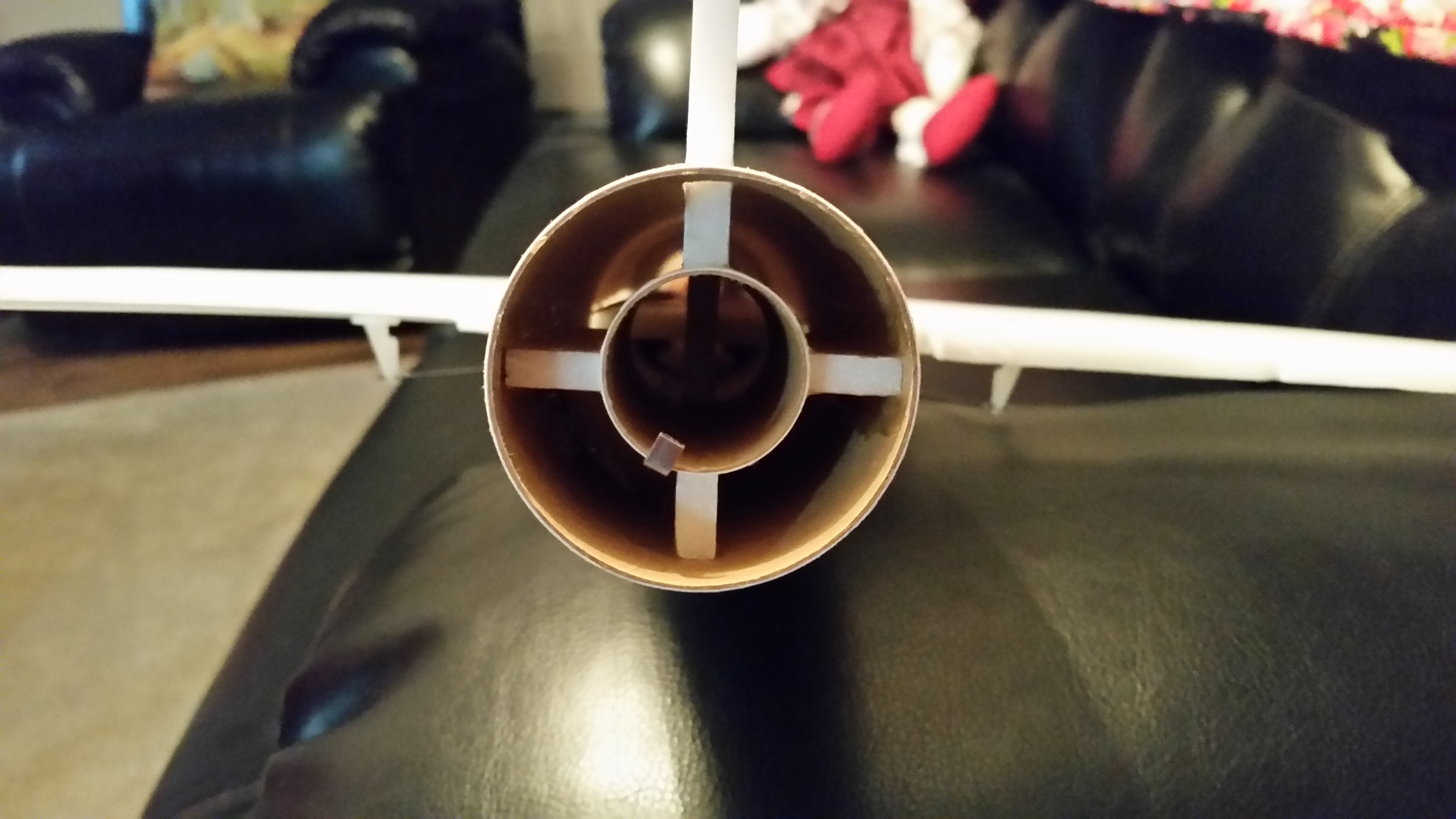
- Glue the two 2.5″ long foam strips onto each side of the motor tube using foam safe CA+. These help center the motor tube in the body tube once you insert it into the vertical fin slot. The strips should be even with the front of the motor tube, which is the end with the motor hook glued in place and taped. Make sure the motor hook is at about a 45 degree angle to the strips so that when you insert the motor mount into the vertical stab, the motor hook won’t be aligned with the foam, the hook needs to be able to move.
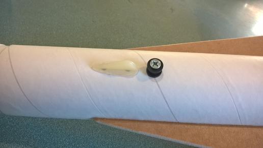
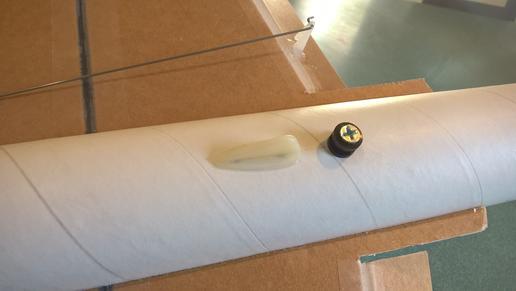
- Using an X-Acto, cut out the hole in the rear and front rail button locations marked on the bottom of the tubes to fit the t nuts. Insert the T nuts from the inside of the tube and install the T nuts, rail buttons and screws, don’t tighten them down really hard, just snug enough to not come out. Make sure they are aligned and don’t bind on the rail. The rail buttons are inset to the right depth so that they do not interfere with the vertical fin or nose cone shoulder. It may be helpful to set the t nut on a ruler, and insert it into the body tube, then press into the hole from the inside then start the screw and rail button pieces. It may be helpful to have someone hold the tube for you. Do this step now as it is not possible to do once the wing and vertical stab are in place.
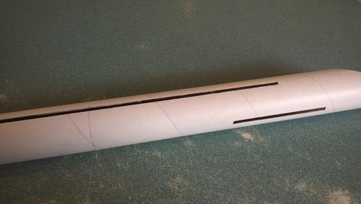
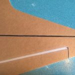
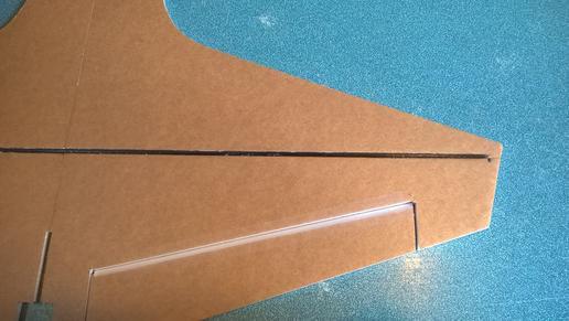
- Cut the slot for the wing once the coupler joint is dry. I used a piece of angle aluminum to do this as it won’t slip while I’m cutting. Take your time and be careful. Make sure to look at the thickness of the wing and cut the slot to just fit the wing thickness, double check the pre-marked lines before you cut for width and length and adjust as needed. Use the spare piece of foam sheet to test the slot, it should go in easily but not be too loose. You can sand the slot for a fine fit if needed.
- Unfold the wing and apply CA+ to the taped joint, then flatten the wing to bond the joint.
- Glue the wing spar in the pre-slotted area on the bottom of the wing. Tape over the spar and the wing joint with the included blenderm tape.
- Test fit the wing in the slot, if it is snug, sand or trim as you don’t want it to drag/damage the wing as you are inserting it.
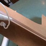
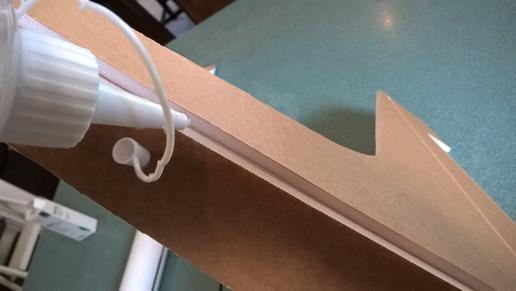
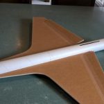
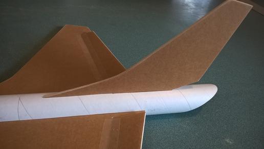
- Test fit the vertical stab into the slot carefully so as to not bend/damage the slot for the motor tube. The vertical stab slot will go through the slot in the wing and help center the wing. Look at the outside of the body tube at the bottom, there is the line for the rear skid that will help you make sure the vertical stab is straight. Once the fit is right, glue the vertical fin into place, carefully press into place in the inside of the body tube and the top of the body tube, make sure the part that glues to the top of the body tube is straight. Apply a light filet to both sides of the vertical stab on the inside and outside of the body tube.
- Make sure the wing is centered at the front of the body tube and apply a fillet of CA+ on both sides of the wing joint the full length.
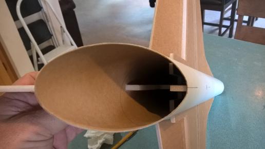
- Test fit the motor mount into the slot in the fin tab. Make sure it fits, or sand very carefully. Apply glue to the top and bottom of the motor tube and insert it till it hits the front of the slot. The two tabs you glued onto the motor tube should be generally horizontal and help center the motor tube. NOTE*** the motor hook is glued at the front, make sure you have the front forward when you glue it in place. You don’t need a lot of glue, as the motor can’t really go anywhere forward as it hits the fin tab at the front.
- Apply CA+ each of the control horns and press them in place in the bottom of each control surface into the pre-made holes. Note the control pushrods go on the inside of each control horn nearest the body tube The holes face forward and the pushrod should be closest to the body tube. Apply a fillet around the control horn and the top of the prongs on the top of the wing.
- Install a landing skid just ahead of each rail button. Use a drill or tool to make starter holes for the prongs. Make sure they are aligned with the buttons and don’t drag on the rail, these help prevent button damage when landing. Use CA+ to glue them in place. Make sure the forward rail button prongs don’t interfere with the nose cone shoulder.
The basic construction is now complete.
Radio Installation
Note: Your radio needs to be configured for Delta mixing, this means that the servo arms will move the same direction during elevator stick movement and opposite for aileron stick movement. Connect your servos to the receiver one in the aileron connection and one on the elevator connection and apply power. Use a servo arm at least 9/16” long and with holes small enough that there won’t be slop with the pushrod wire when installed. I use the hole furthest out on the servo arm, to maximize movement. On some servos there are a long two-ended servo arm, you can trim off one end if needed to get sufficient length. Zero out any trim settings on the transmitter. The model once the motor has burned out is nose heavy and flying wings lose pitch authority when nose heavy so you want as much up elevator travel for trim/flare as possible.
- Connect a servo to each pushrod. If the pushrod is too tight, you can use twist an X-Acto knife in the servo arm hole to make it larger, but be careful and do not make it too large. Once connected, tape each servo in place so that the control surfaces are centered. Flip the model right side up and look at it from the rear. Moving the transmitter stick back(up elevator) should move both elevons up. Moving the transmitter stick to the right should move the right elevon up and the left elevon down. If you can’t get the servo reversing to give you the right polarity try swapping aileron/elevator inputs to the receiver or turning the servos over and swapping the servo arms to the other side of the output shaft. If that is correct, continue.
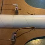
- Flip the model upside down and supported. The servos may be attached to the model using double back servo mounting tape(not included) or by directly gluing the servo to the wing with foam safe CA+. Double back servo tape can loosen over time and with exposure to heat, I prefer to glue the servo in place. With the radio still on, put a moderate amount of glue on the servo, being careful not to get any near the output shaft, and set it in place on the model keeping the control surface centered. Do the same to the other side. Make sure the glue is set before continuing. Note** The servo wire should point toward the front of the model and the servo should be butted next to the body tube. Apply a fillet of glue around the servo/wing to help secure it and let it cure.
- Attach a 6″-12″ servo extension to each servo.You just need to be able to route the wire to the front of the tube to attach it to the receiver.
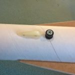
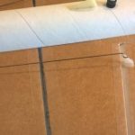
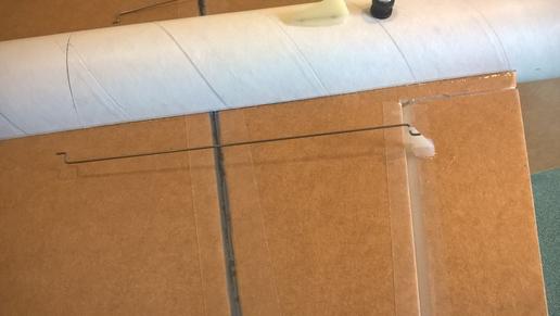
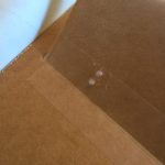
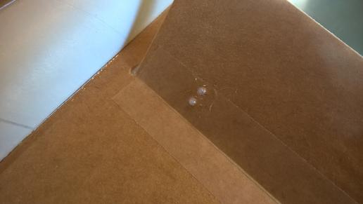
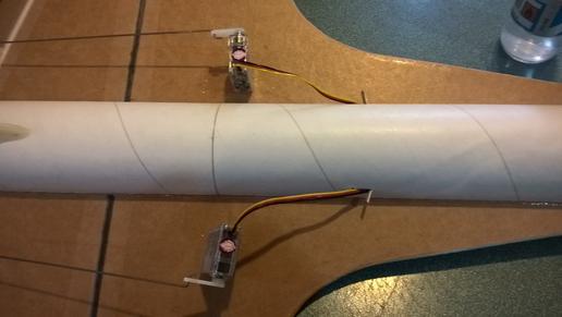
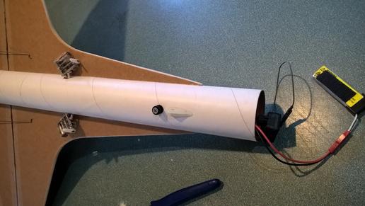
- Make a 1/8″ wide by 1/2″ long slot in the body tube on each side of the body tube near the servo and pass the wires through to the inside and toward the front. On my model I just made a U shaped cut, folded the cardboard forward, inserted the wire then folded the cardboard back over the slot/wire. I then glued the cardboard tab in place. See photo for more clarity.
- Attach the servo wires to the receiver and make sure they are going the right direction.
- Flip the model back right side up. Make sure the control surfaces are centered, use trims if needed. Now measure the control surface movement. Full elevator movement should be 7/8” in each direction, aileron movement should be 1/2″ in either direction. Since the model will be nose heavy, extra elevon movement helps to give sufficient authority during glide.
- If you have a flap/elevator mix you can program up elevator to a switch setting. The model needs approximately 3/16″ of down trim for boost and 1/4″ of up trim for glide. If you can’t set the up elevator trim to a switch on your radio you’ll have to manually put in boost and glide trim which is hard to do while flying the model.
- Use the included Velcro to attach the receiver insde the body tube just against the front of the wing. This allows you to be able to remove and replace the receiver if needed for repairs or for removing the servo wires.
- I attached the battery inside the nose cone on the shoulder with velcro.
- Insert your heaviest loaded rocket motor into the motor mount
- Support the model at the balance point indicated for boost. I use two pencils with the eraser pointed up and held in place with a small hand vice. Place the model upside down on the pencil erasers on the balance point indicated above. Use pieces of the included lead weight as far forward into the tip of the nose to balance it, or in the tail as needed. Glue the lead weight in place so it does not shift during flight. Do not try to fly the model too nose or tail heavy. Remember, a nose heavy model flies poorly, a tail heavy model flies once
- I can only recommend testors/model master enamel spray at this time, others I’ve tried damage the foam surface. I recommend flat colors as they dry faster and the surface imperfections of foam aren’t as noticable.
- You can use a black fine line sharpie to add panel lines if desired.
- Re-install the receiver and battery
Flying: See the General Instruction link at the top for flying instructions. Be ready on the first few flights to keep the model straight till you have the trims set perfectly for boost and glide.
-
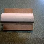
- Kit Parts
-
- Glue spacers onto motor tube
-
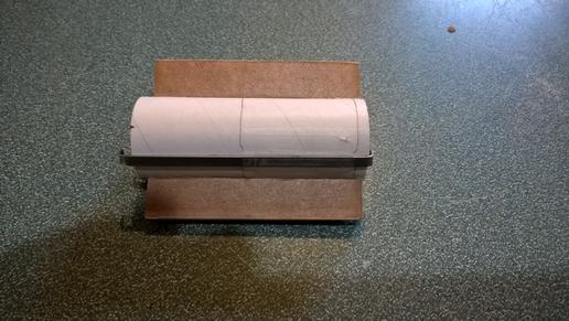
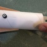
- Join Body Tubes
-
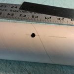
- Cut rail button holes
-
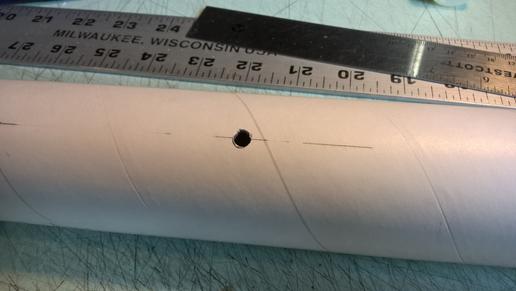
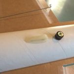
- Install Rail Buttons
-
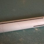
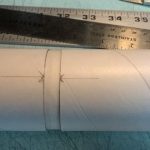
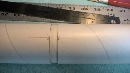
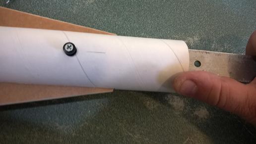
- Cut wing slots
-
- Glue wing joint
-
- glue wing spar
-
- Tape over spar and center joint
-
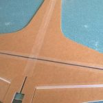
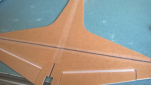
- insert Wing into body tube
-
- Test fit tail and glue in place.
-
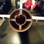
- Motor mount installed
-
- Install front skid
-
- Install rear skid
-
- Install control horns and pushrods
-
- add glue on top of horn prongs to capture the horn in place
-
- Glue servos in place with control surfaces level, then cut slots to route the servo wires forward
-
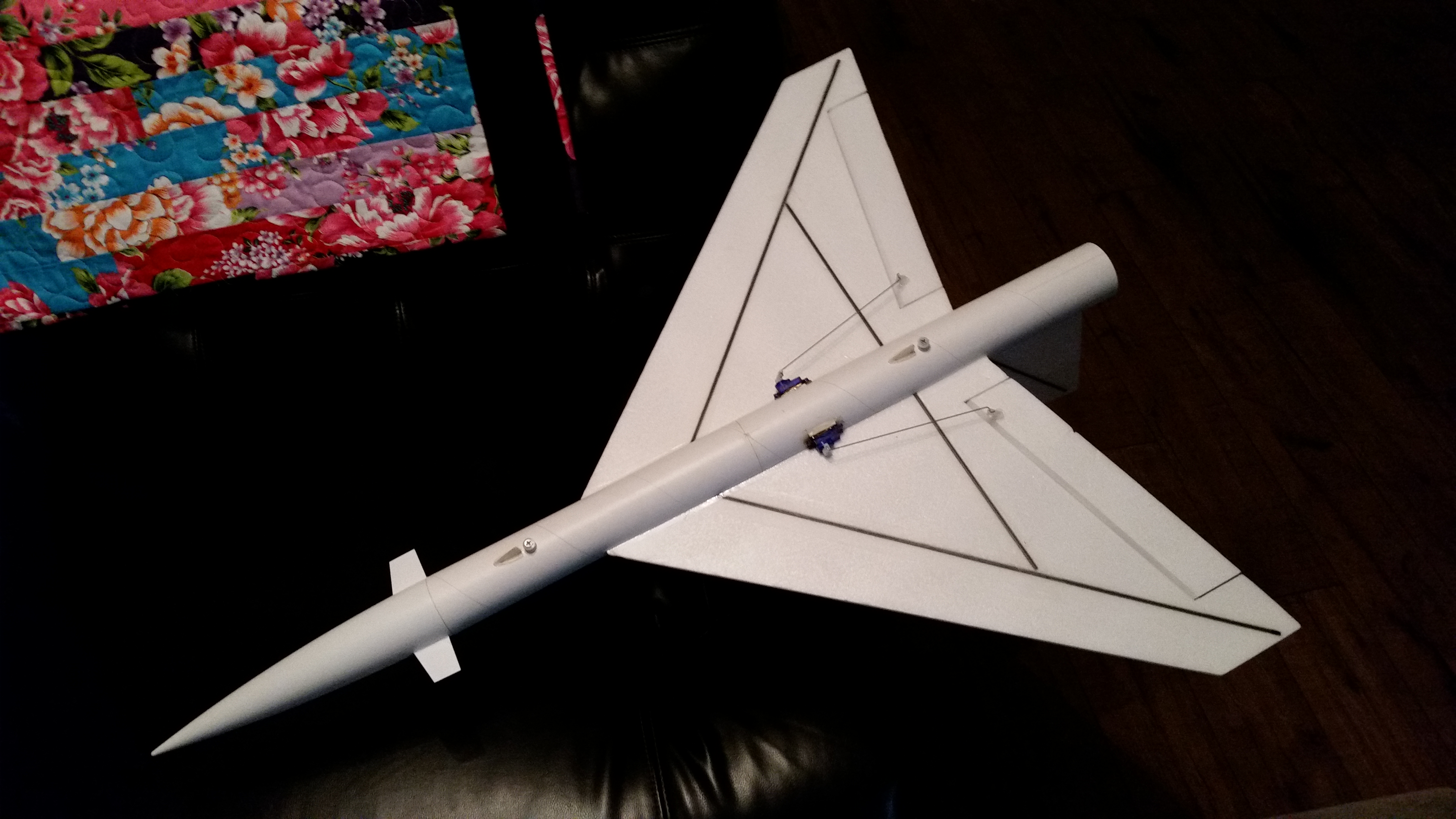
- Servos installed, these are shown inset, I prefer to keep the pushrods perpendicular to the hinge line and have the servos away from the body tube.
-
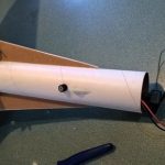
- connect servo wires to receiver
-
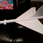
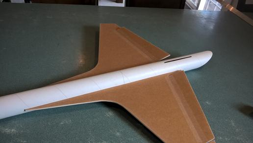
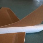
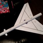
- Airframe complete