
StratoDart X Rocket Glider Kit
The StratoDart X RC Rocket glider kit is an updated version of the original Stratodart using MPF wings and a different motor mount system, and nose cone. All other specs, features and flight performance is identical to the original. It features a mid mounted delta wing, a plastic nose cone, 2″ white tubing for the body and MPF wing and depron tail surfaces. It has a light wing loading giving it a very nice glide and easy/stable boost. Construction is very simple and takes about an hour and a half. The only hard part on this model is cutting the slot for the wing after you assemble the body tubes, however the slot locations are pre-marked for you. You will need two 10 gram type servos, two 12″-18″ servo extensions, a receiver, and a small 500mah single cell lipo battery. You will need a transmitter with delta or elevon mixing. Stickershock has cut vinyl decal sets for both Pan Am and TWA logos that will fit this model. Click here:
Please refer to the General Information Link above then read the instructions completely before starting assembly. The assembly photos are for general reference but may not include every step in the instructions. If you want hardcopy to work from, all you have to do is click/drag/select and copy all of the text below, open word and paste with “keep original format” and it looks exactly like it does online then you can print it.
CG location for rocket flight: 13″ measured from the rear end of the main body tube assembly, this should be approx 1/2″ behind the joint between the two body tubes.
Welcome to the world of rocket boosted radio control gliders. This is not a model for a novice RC pilot, but anyone who is comfortable with RC flying of a medium speed model should be fine. Read through the instructions, look at the photos and be sure you understand the step before commiting to cutting or glue.
StratoDart X Rocket glider instructions
Identify all pieces, the kit should contain:
1 wing taped together
1 wing spar(carbon fiber)
1 Nose Cone
1 vertical stabilizer
2 control horns w/pushrods
1 2.5″ long foam strips for centering the motor tube.
2 Body Tubes
Motor mount
Velcro(for battery and rx/bec attachment)
2 Rail buttons with t nuts/screws
2 landing skids
3M blenderm tape
Lead weight
Spare depron
Notes before starting:
Reference to CA+ means foam safe CA+, normal CA+ will melt the foam! Normally you need to use accelerator to get the CA to set on the foam since there is nothing for it to soak into and activate.
You may use 220-320 grit sandpaper and a sanding block to slightly round the edges of the foam if you prefer that look. It will not markedly impact the flight performance either way. Be very careful and use a light touch, it is very easy to catch the foam on the edge of the paper and tear the foam. Do any sanding before assembly.
Epoxy is not needed in this model. Weight is critical and the model is designed for the thrust and flight loads. Weight in the rear end is bad and will require additional weight in the front of the model.
Assembly:
- Unfold the wing and glue the pre-taped joint using CA+ and accelerator, make sure it is flat
- Glue the wing spar in the pre-slotted area on the bottom of the wing with CA+ and then tape over with the included blenderm tape.
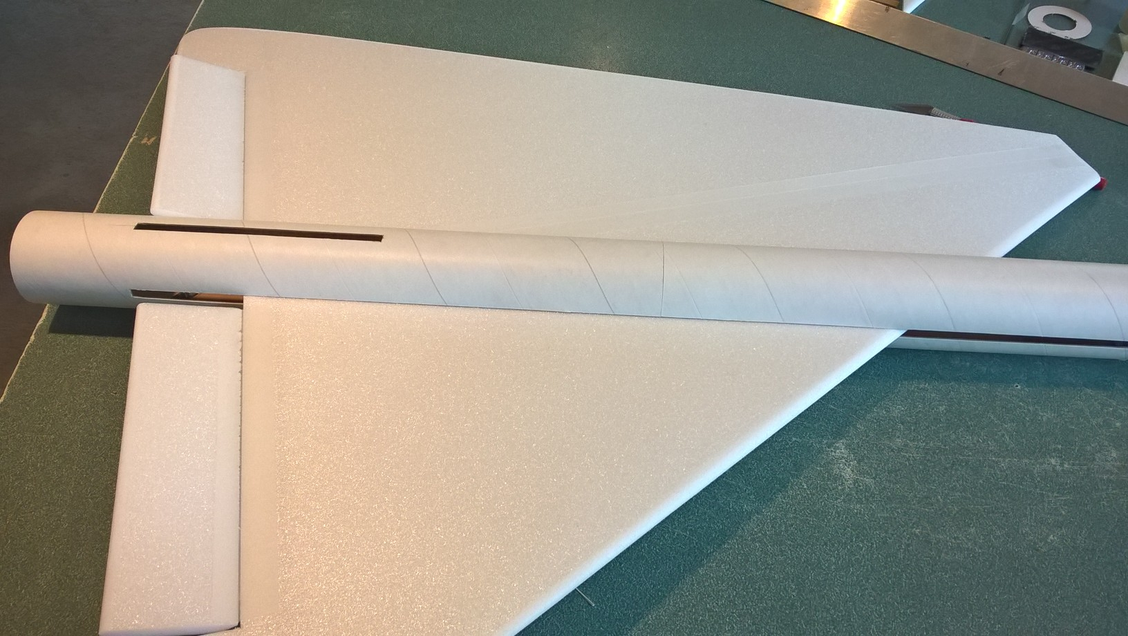
- Body Tubes. One tube will have a coupler glued in place. Glue the other tube onto the coupler, make sure the small arrow marks are aligned on the two tubes, that will ensure the wing slot mark and rail button marks are properly aligned. Use CA+ sparingly, as you will need to cut through the coupler to cut the wing slot.
- Cut the slot for the wing. I used a piece of angle aluminum to do this as it won’t slip while I’m cutting. Take your time and be careful. Test fit the wing in the slot, if it is snug, sand or trim as you don’t want it to drag/damage the wing as you are inserting it.
- Make a hole in the rear and front rail button locations marked on the bottom of the tubes to fit the t nuts. Insert the T nuts from the inside of the tube and install the T nuts, rail buttons and screws, don’t tighten them down really hard, just snug enough to not come out. Make sure they are aligned and don’t bind on the rail.
- Insert the wing and make sure it is centered, then glue in place with foam safe CA+
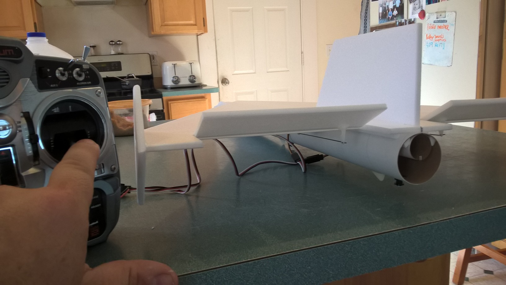
- Test fit the vertical tail into the slot and make sure it fits. Make sure the tail is straight with no warps, bend carefully by hand to straighten it if needed. Glue into the slot using foam safe CA+ making sure the tail is perpendicular to the wing and is straight.
- Glue the foam centering strip on the motor mount tube. The strip glues onto the tube flush with the front of the tube, the front of the motor mount has the motor hook taped and glued. The strip should glue at approx a 45 degree angle to the motor hook so that when glued in place the hook will be clear of the foam. See picture for clarification.
- Glue the motor mount into the rear of the model, the motor mount will butt against the wing inside the tube. You don’t need a lot of glue here, just enough to keep it from falling out, the wing will keep it from moving forward. The support strip should be pointing down and the vertical stab tab will make contact with the top of the motor tube. Make sure you glue the tube so that the glued/taped end is forward. If you need to sand the tab glued on the motor tube so that it fits lightly sand till it will insert fully.
- Glue each control horn in place on the bottom of the surface, the holes should be pointing toward the front of the model and the pushrod should be closest to the body tube. Repeat on the other side.
- Put some CA on the top of the control surface where the horn prongs stick through, this locks it in place.
- Install a landing skid just ahead of each rail button. Use a drill or tool to make starter holes for the prongs. Make sure they are aligned with the buttons and don’t drag on the rail, these help prevent button damage when landing. Use CA+ to hold them in place. Make sure the forward rail button prongs don’t interfere with the nose cone shoulder.
The basic construction is now complete.
Radio Installation
Note: Your radio needs to be configured for Delta mixing, this means that the servo arms will move the same direction during elevator stick movement and opposite for aileron stick movement. Connect your servos to the receiver one in the aileron connection and one on the elevator connection and apply power. Use a servo arm at least 9/16” long and with holes small enough that there won’t be slop with the pushrod wire when installed. I use the hole furthest out on the servo arm, to maximize movement. On some servos there are a long two-ended servo arm, you can trim off one end if needed to get sufficient length. Zero out any trim settings on the transmitter. The model once the motor has burned out is nose heavy and flying wings lose pitch authority when nose heavy so you want as much up elevator travel for trim/flare as possible.
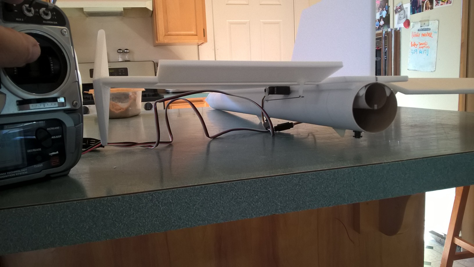
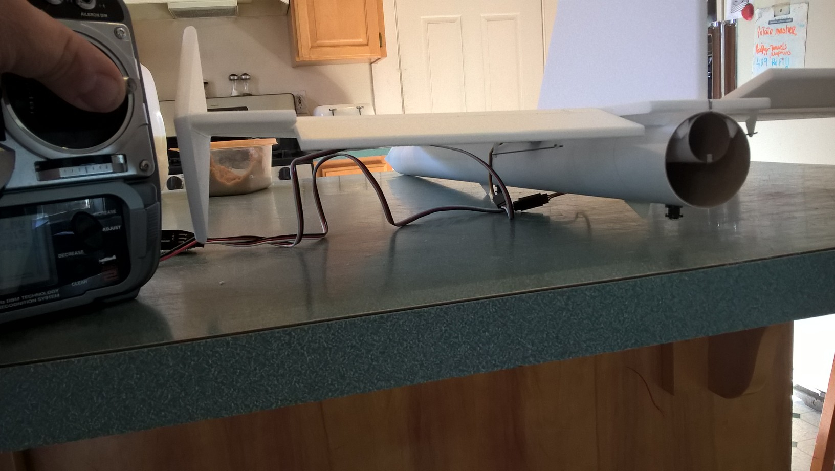
- Connect a servo to each pushrod. If the pushrod is too tight, you can use twist an exacto knife in the servo arm hole to make it larger, but be careful and do not make it too large. The servo electrical wires should be pointed toward the front of the model and the servos should be right next to the body tube. Once connected, tape each servo in place so that the control surfaces are centered. Flip the model right side up and look at it from the rear. Moving the transmitter stick back(up elevator) should move both elevons up. Moving the transmitter stick to the right should move the right elevon up and the left elevon down. If you can’t get the servo reversing to give you the right polarity try swapping aileron/elevator inputs to the receiver or turning the servos over and swapping the servo arms to the other side of the output shaft. If that is correct, continue.
- Flip the model upside down and supported. The servos may be attached to the model using double back servo mounting tape(not included) or by directly gluing the servo to the wing with CA+ or a small amount of epoxy. Double back servo tape can loosen over time and with exposure to heat, I prefer to glue the servo in place. With the radio still on, put a small amount of glue on the servo, being careful not to get any near the output shaft. And set it in place on the model keeping the control surface centered. Do the same to the other side. Make sure the glue is set before continuing. The servo and pushrod should be at 90 degrees to the hinge line so that it moves easily and fully. The z bends in the pushrods are made with a tool but they may not align perfectly depending on servo placements, you can use a needle nose pliers to make little adjustments to the bend angle if needed.
- Flip the model back right side up. Make sure the control surfaces are centered, use trims if needed. Now measure the control surface movement. Full elevator movement should be 1” in each direction, aileron movement should be 1/2″ in either direction. Since the model will be nose heavy, extra elevon movement helps to give sufficient authority during glide.
- If you have a flap/elevator mix you can program up elevator to a switch setting. The model needs approximately 1/4” of up elevon during glide. If you can’t set the up elevator trim to a switch on your radio you’ll have to manually put in boost and glide trim which is hard to do while flying the model.
- Attach a 16-18″ servo extension to each servo.You just need to be able to route the wire to the front of the tube to attach it to the receiver.
- Make a 1/8″ wide by 1/2″ long slot in the bottom of the wing/fuselage on each side and pass the wires through to the inside and toward the front. On my model I just made a U shaped cut, folded the cardboard forward, inserted the wire then folded the cardboard back over the slot/wire. I then taped over that with blenderm tape to avoid having a large open slot. See photo for more clarity. You can also just cut the slot out completely and cover it over with tape after inserting the wire.
- Attach the servo wires to the receiver and make sure they are going the right direction. Tape down the servo wires to the wing and tape over the slot in the body tube.
- Use the included Velcro to attach the receiver 2″ from the front of the body tube at the top(or enough to allow the wires to clear the shoulder of the nose cone). This allows you to be able to remove and replace the receiver if needed for repairs or for removing the servo wires. I attached the battery inside nose cone on the shoulder. Alternately to avoid as much nose weight you can velcro the receiver into the nose as well which moves some weight forward.
- Insert your heaviest loaded rocket motor into the motor mount
- Support the model at the balance point indicated for boost. I use two pencils with the eraser pointed up and held in place with a small hand vice. Place the model upside down on the pencil erasers on the balance point indicated in the kit spec sheet. Use the included lead weight to balance it by placing it as far forward in the nose or at the tail of the model as needed. Do not try to fly the model with it balancing it behind this point. The adage is, a nose heavy model flies poorly, a tail heavy model flies once
- If you use self adhesive vinyl from stickershock23, it helps once applied to use a hair dryer on hot to soften the material and then push it down onto the model with a towel. It helps it confirm and stick much better.
- Use a black sharpie to add panel lines if desired
- Re-install the receiver and battery
Flying: See the General Information link at the top for flying instructions. Be ready on the first few flights to keep the model straight till you have the trims set perfectly for boost and glide.
-
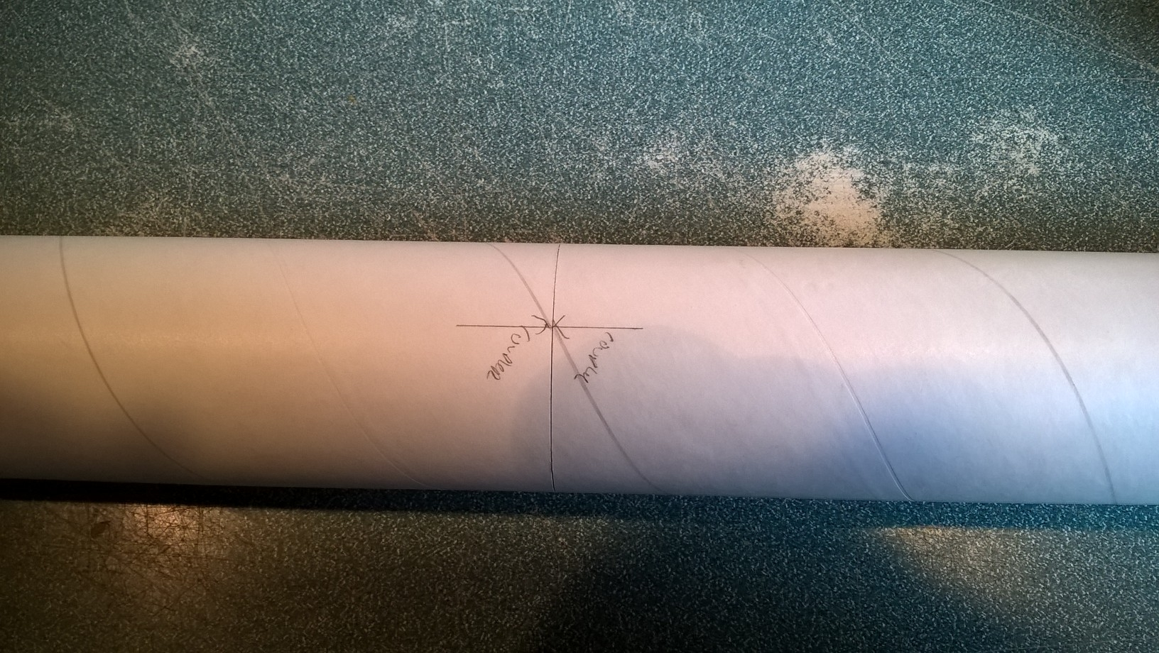
- Install the rail buttons, then Join tubes with the coupler keeping arrows aligned on the bottom wing line mark
-

- cut wing slots
-
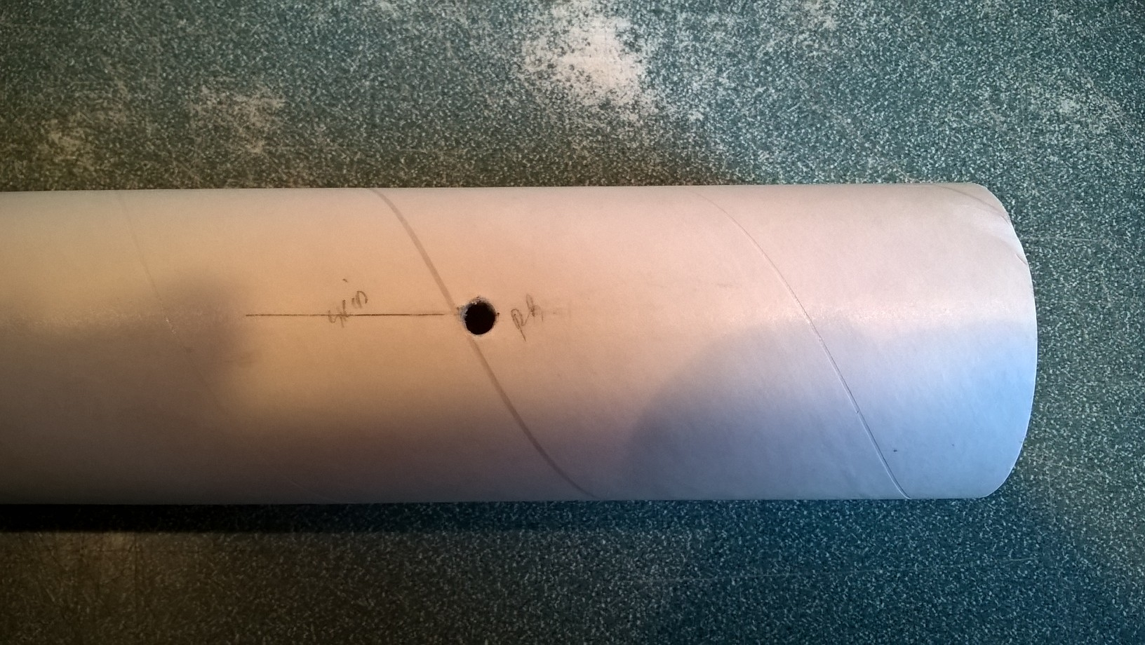
- cut rail button holes
-
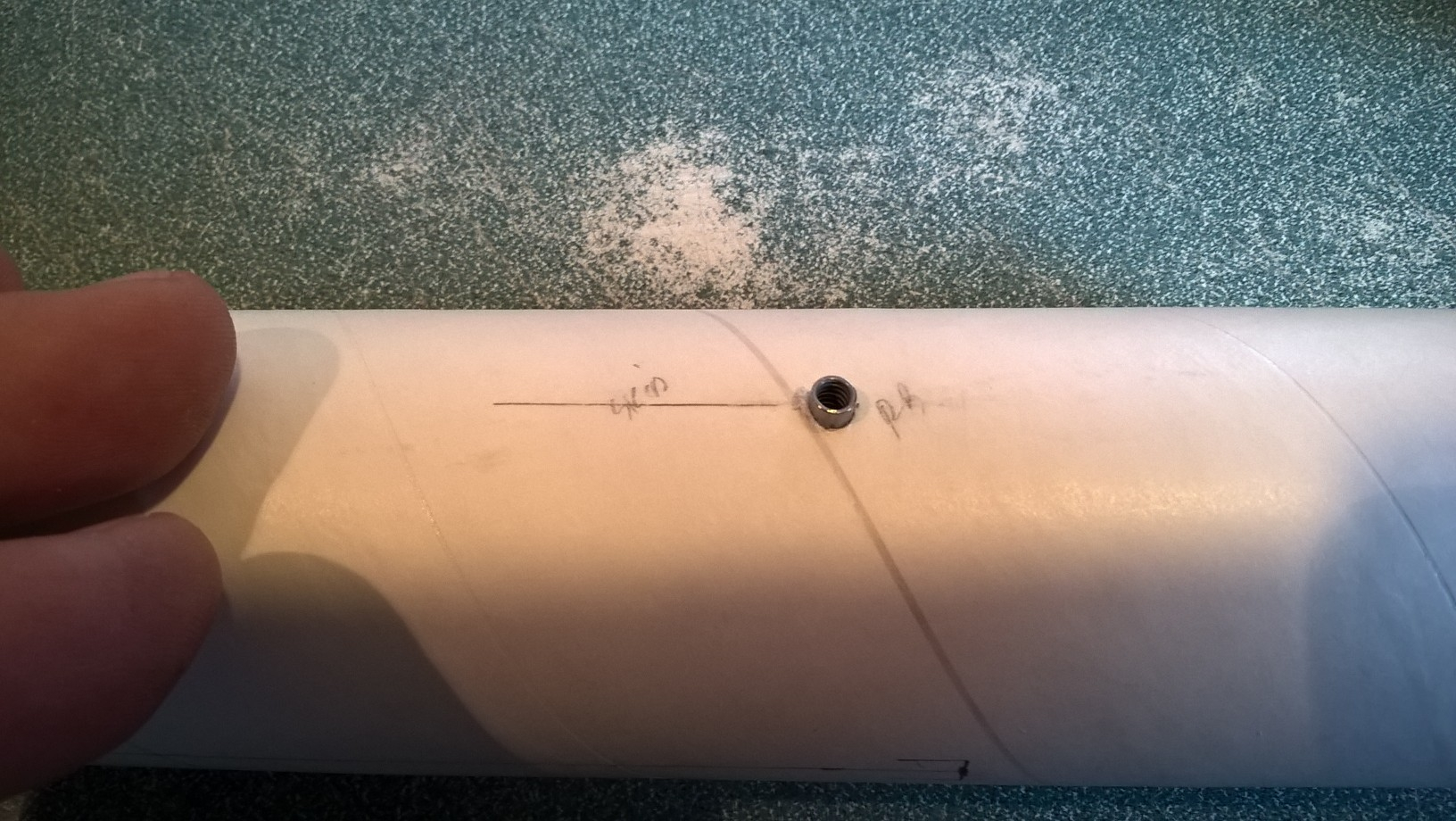
- install t nuts and hold in place
-
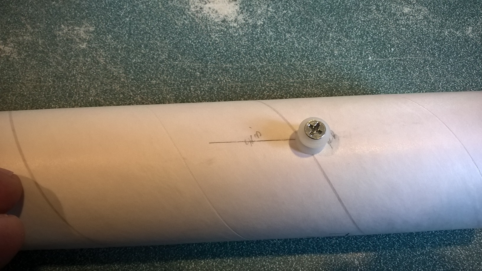
- add rail buttons
-
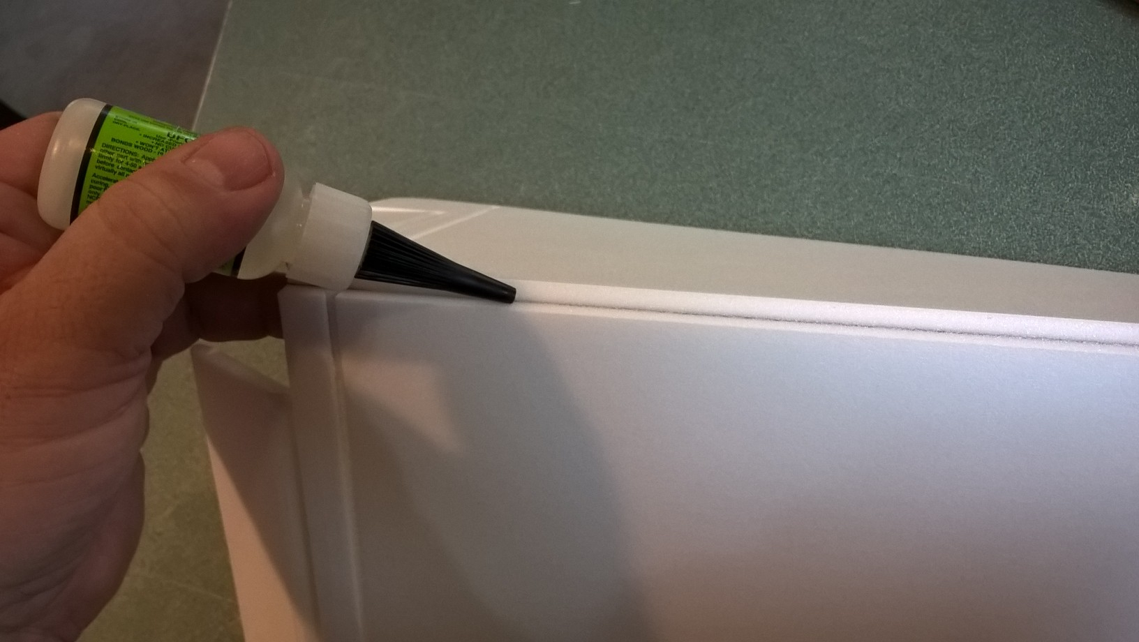
- glue the wing joint
-
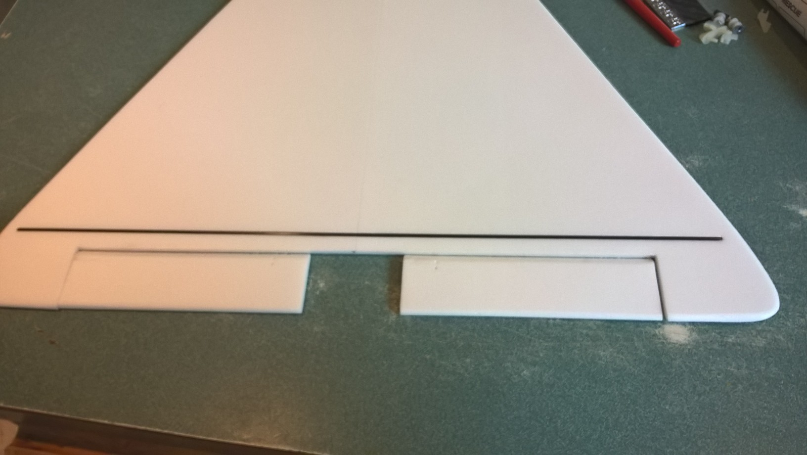
- glue the spar and tape over the spar and wing joint with blenderm
-
- test fit wing in place
-
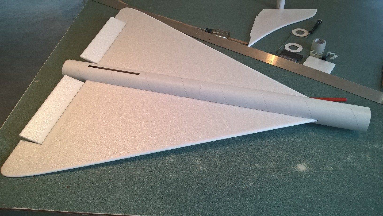
- glue the wing in place when centered
-
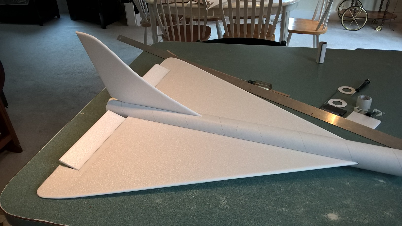
- glue in the vertical stab
-
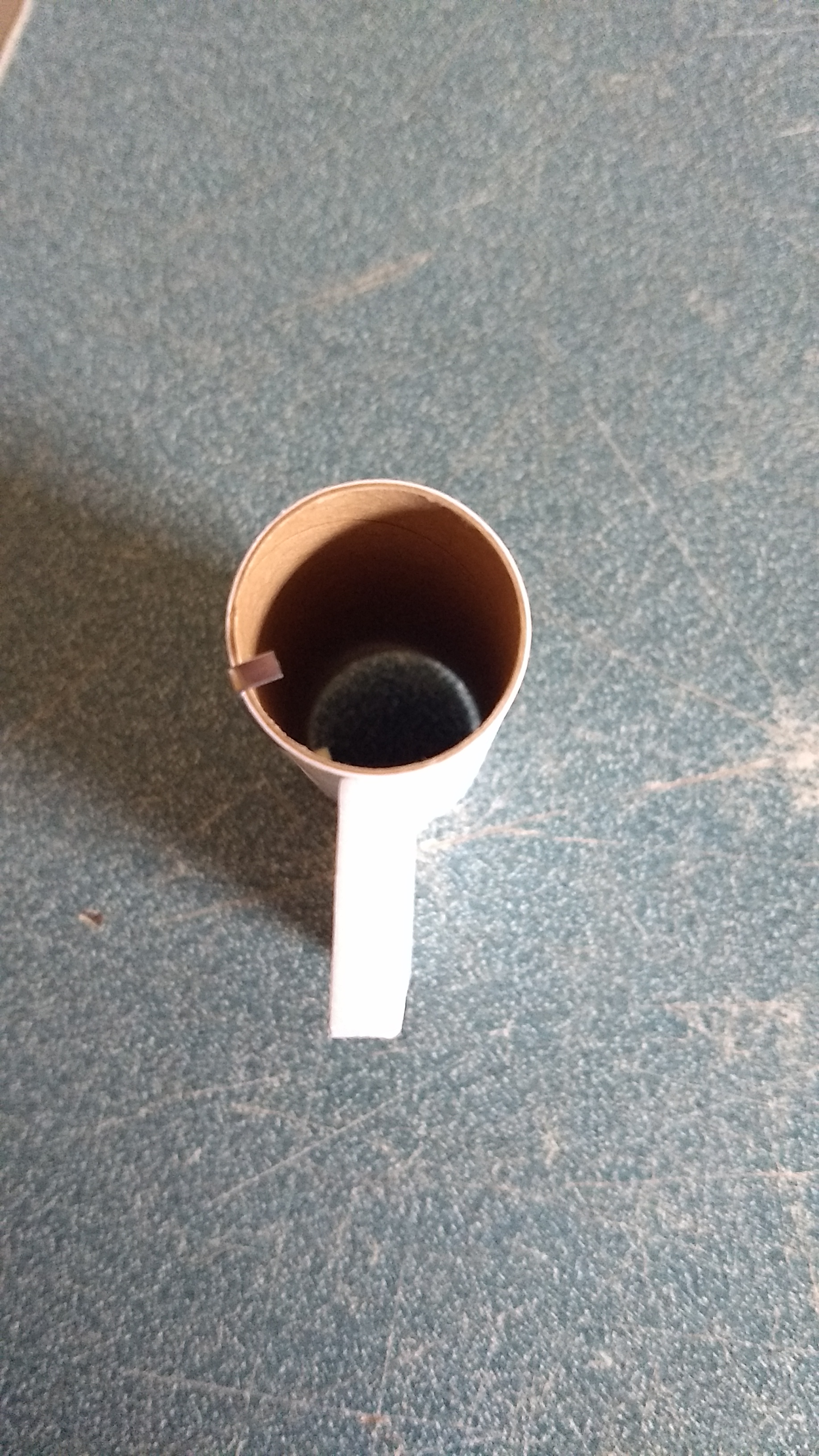
- Glue the foam strip onto the motor tube with the hook at a 45 degree angle to the strip when viewed from the rear as shown.
-
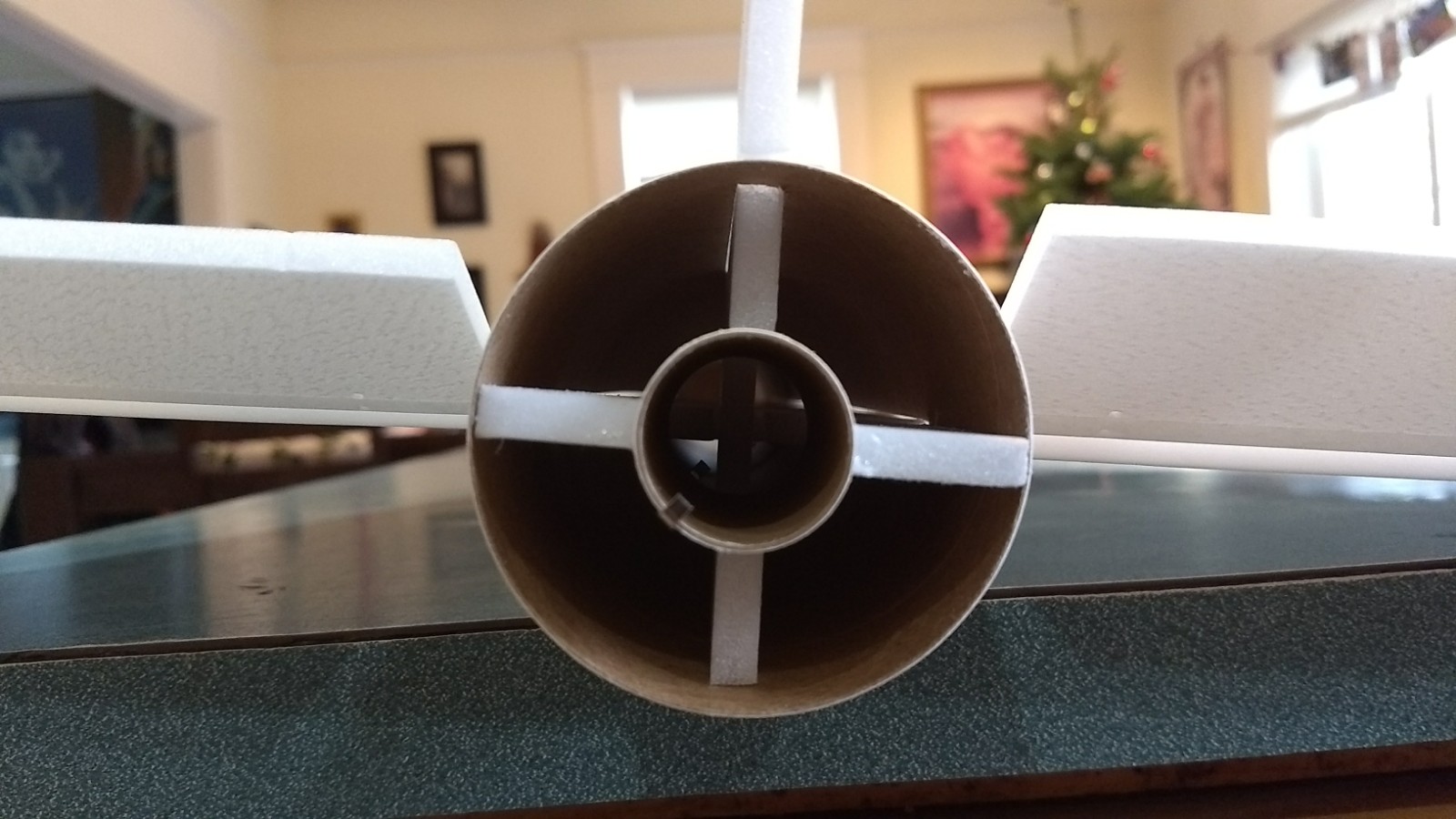
- Test fit then glue in the motor mount in place, sand the strip on the motor tube if needed so that the motor tube snugly fits into the slot in the wing and between the vertical stab tab. Make sure the vertical stab stays perpendicular to the wing as you glue the motor tube in place.
-
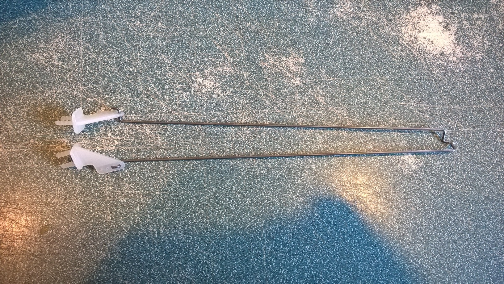
- pushrods, one for each side
-

- install each pushrod into the bottom of the control surface.
-
- add glue to the top pins of the control horn
-
- mark for the skids
-
- install the skids in front of each rail button
-
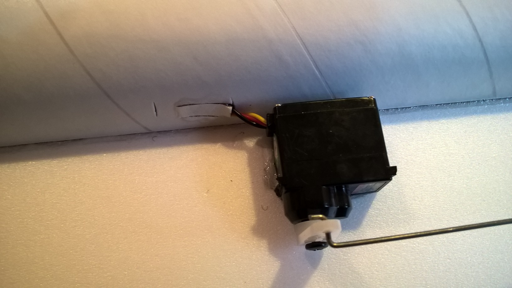
- showing how the servo wires are routed into the tube
-
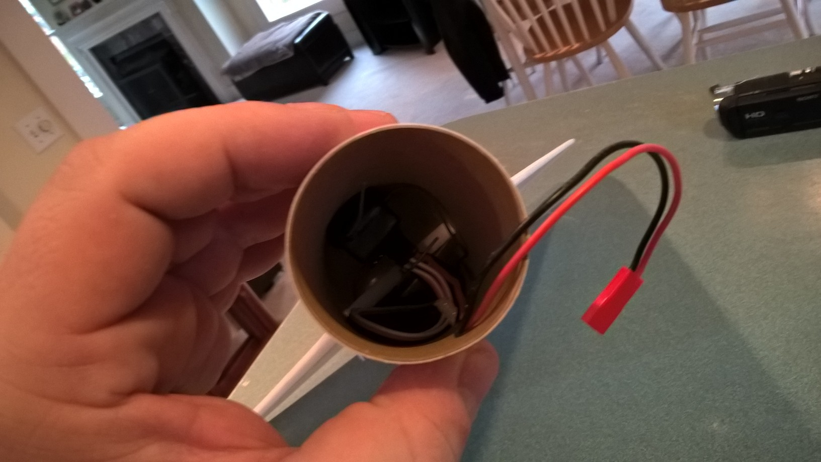
- connect the servos to the receiver and hold the receiver in place using velcro inside the body tube. I also attached the flight battery inside the body tube for CG reasons.
-

- put velcro in the nose cone for the battery and receiver
-
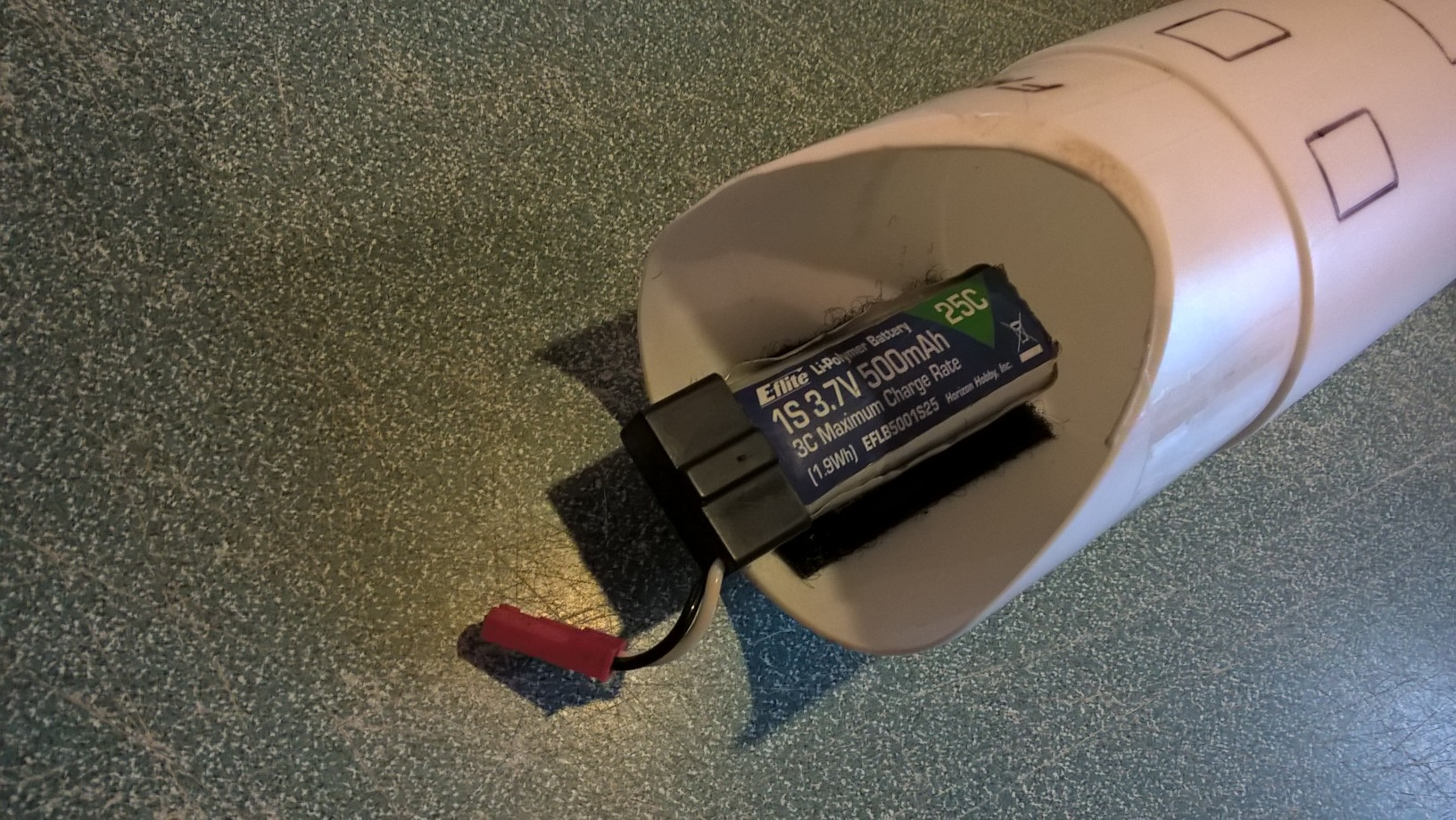
- battery mounted in the nose cone
-
- boost trim(This is a different model, picture shown for general reference)
-

- glide trim(This is a different model, picture shown for general reference)
-
- left aileron(This is a different model, picture shown for general reference)
-
- right aileron(This is a different model, picture shown for general reference)
-
- up elevator(This is a different model, picture shown for general reference)
-

- down elevator(This is a different model, picture shown for general reference)
-
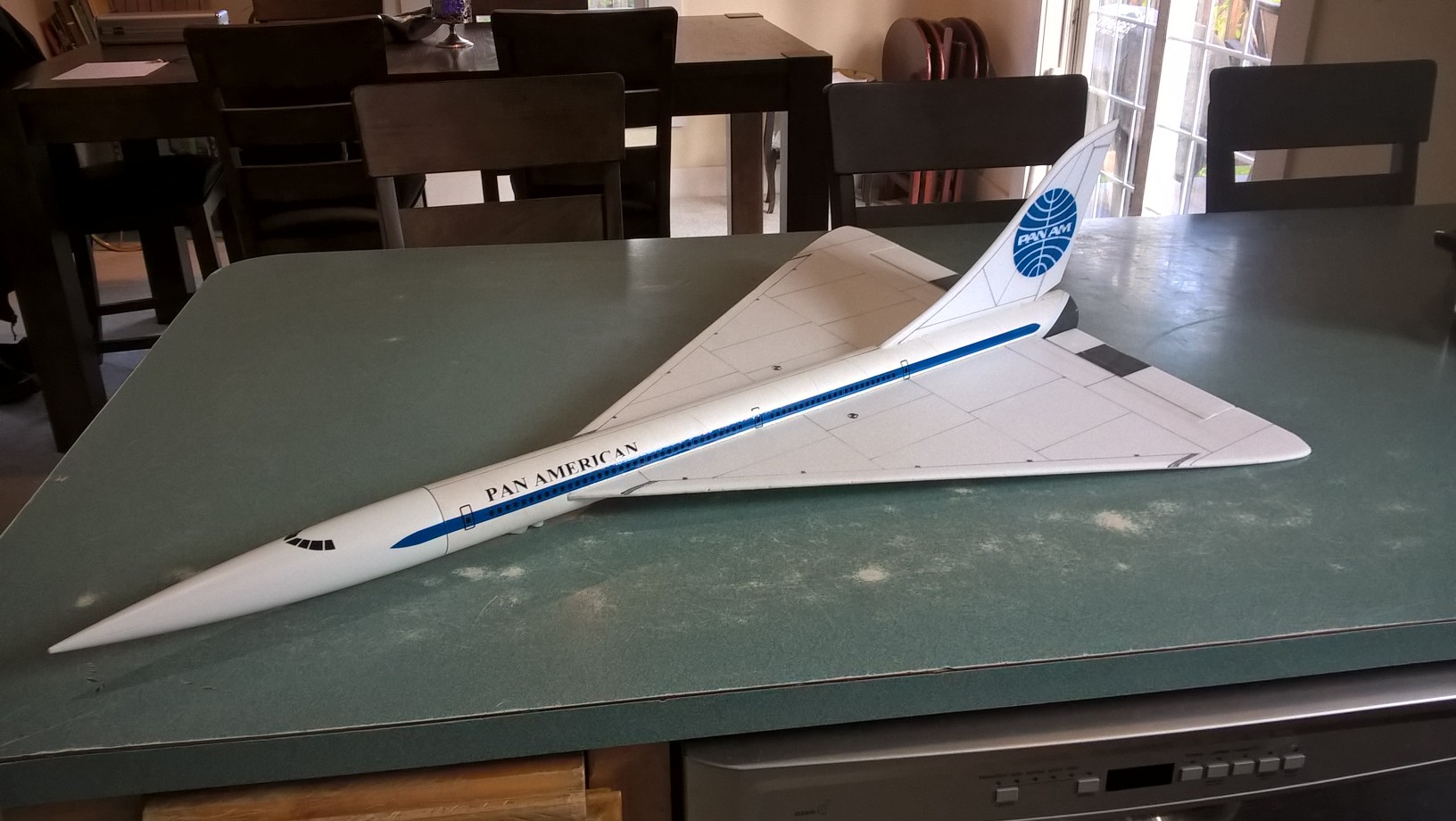
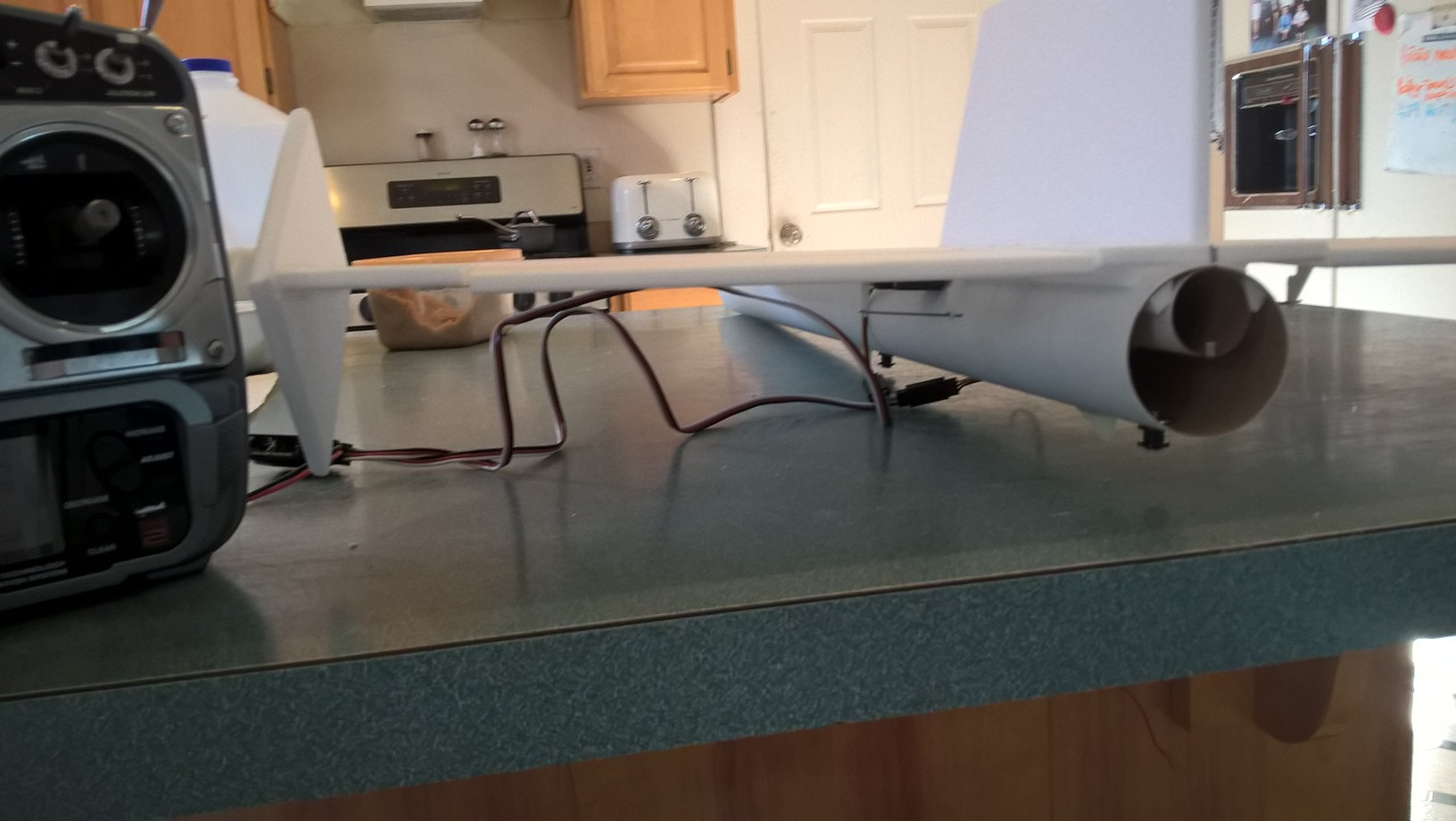
- Finished Model with stickershock Pan Am markings
-
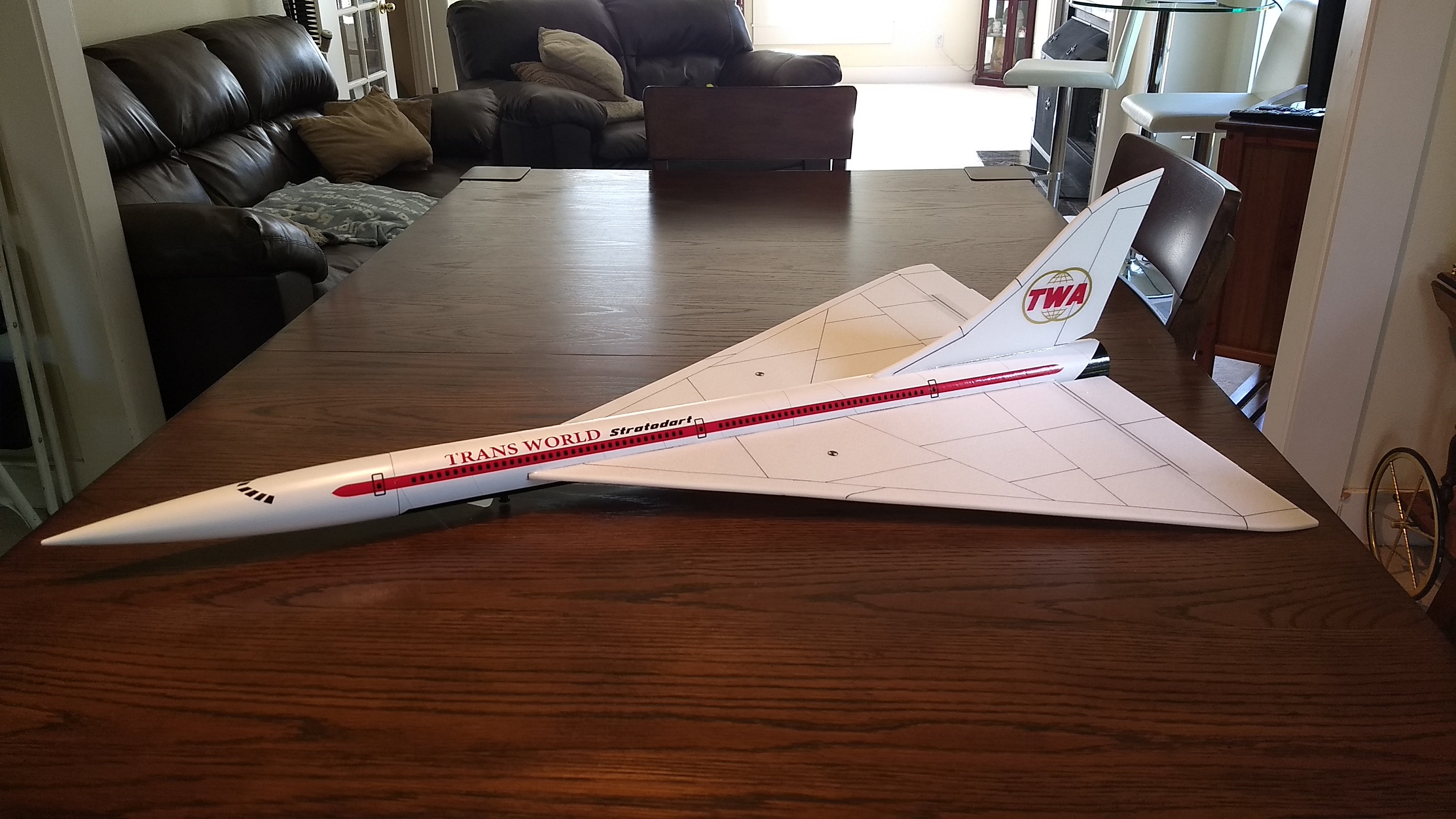
- Finished model with stickershock TWA markings