HABU RC rocket glider kit
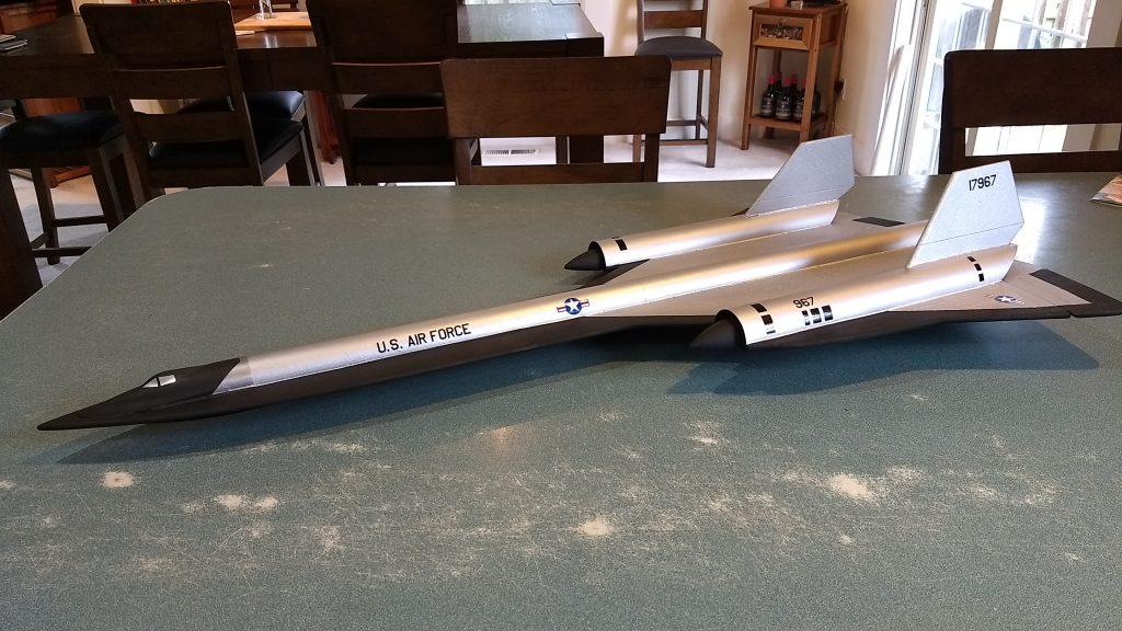
The Habu RC Rocket glider kit comes with white BMS tubing for the body and engine nacelles and Model Plane Foam (MPF) wing and tail surfaces. You will need two 8-11 gram type servos, a receiver, and a small 500mah single cell lipo battery and an 18″-20″ servo extension. You will need a transmitter with delta or elevon mixing. Foam safe CA+ is the only correct glue to use for all construction on this model. Any other adhesive will add weight in the wrong place, and reduce flight performance. Please refer to the General instructions for all kits tab above, then read these instructions completely before starting assembly. Wingspan 21.5″, length 39″(about 1/32 scale) weight 13.25 oz rtf.
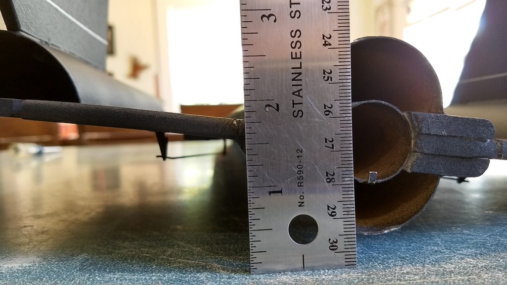
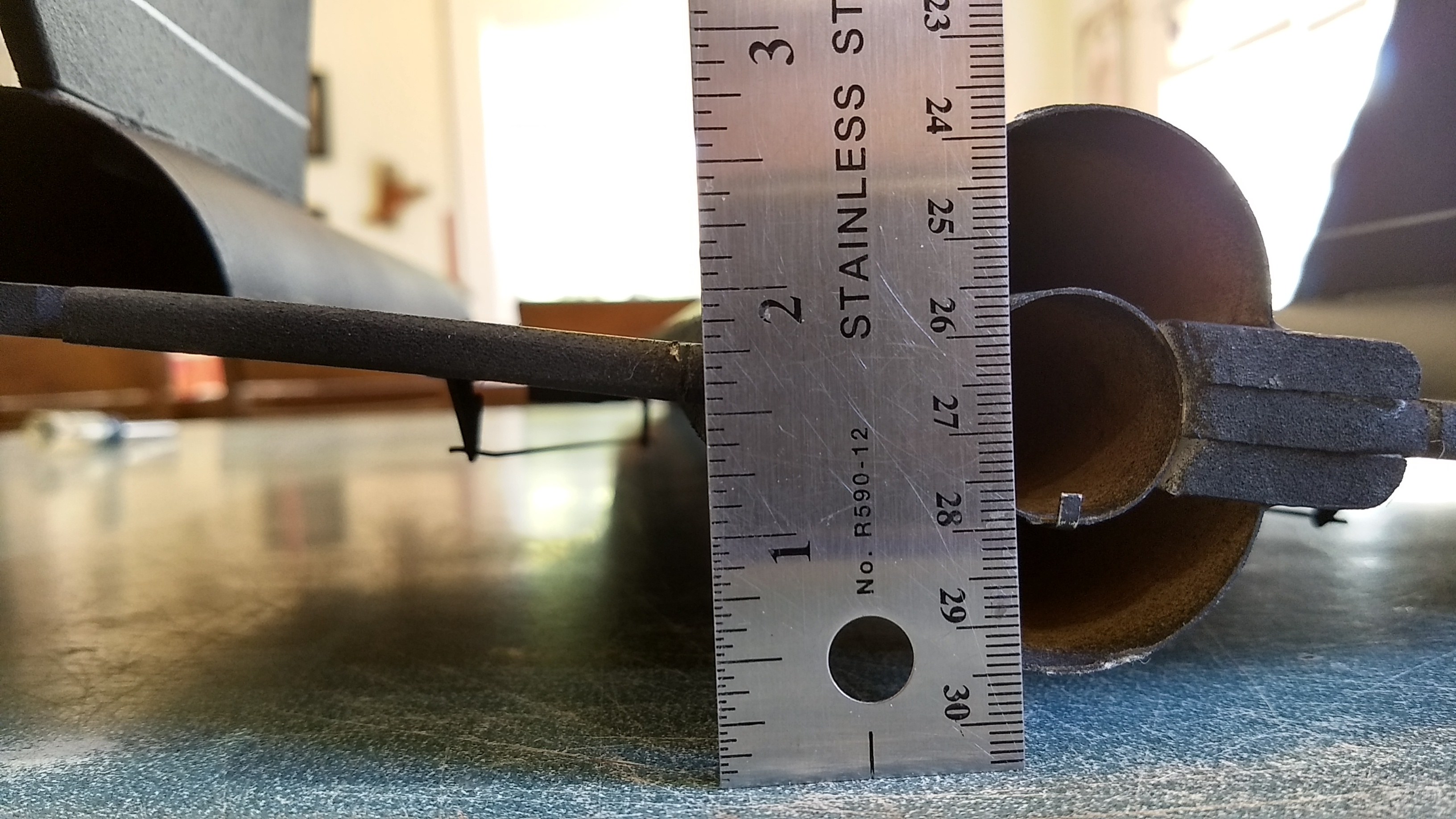
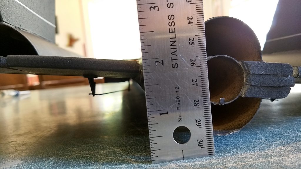
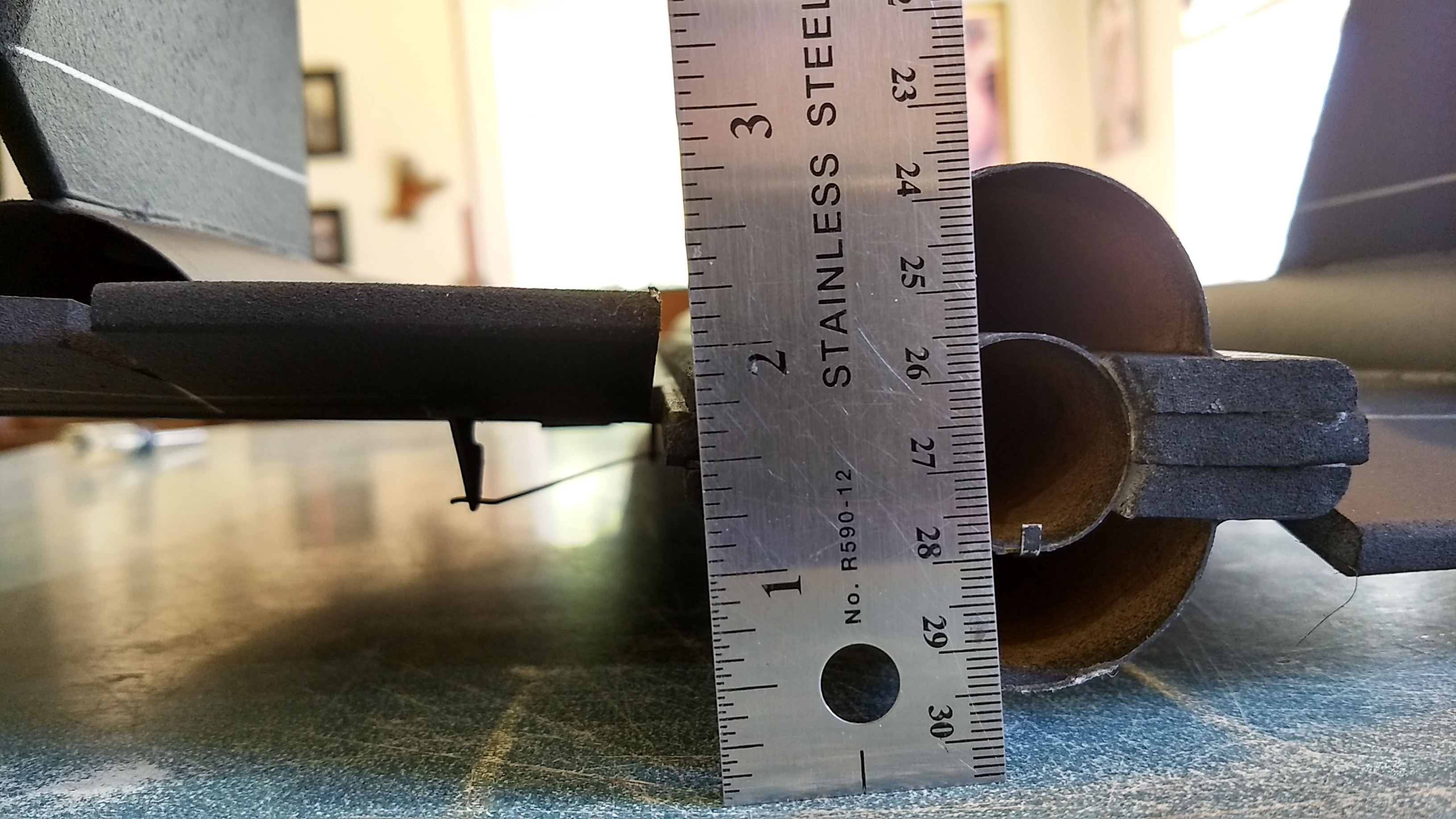
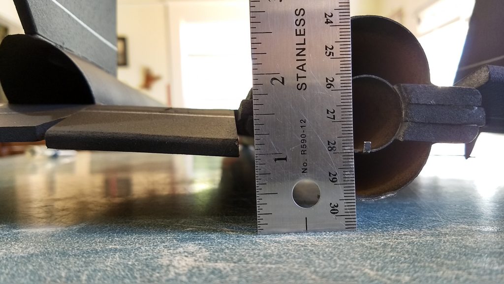
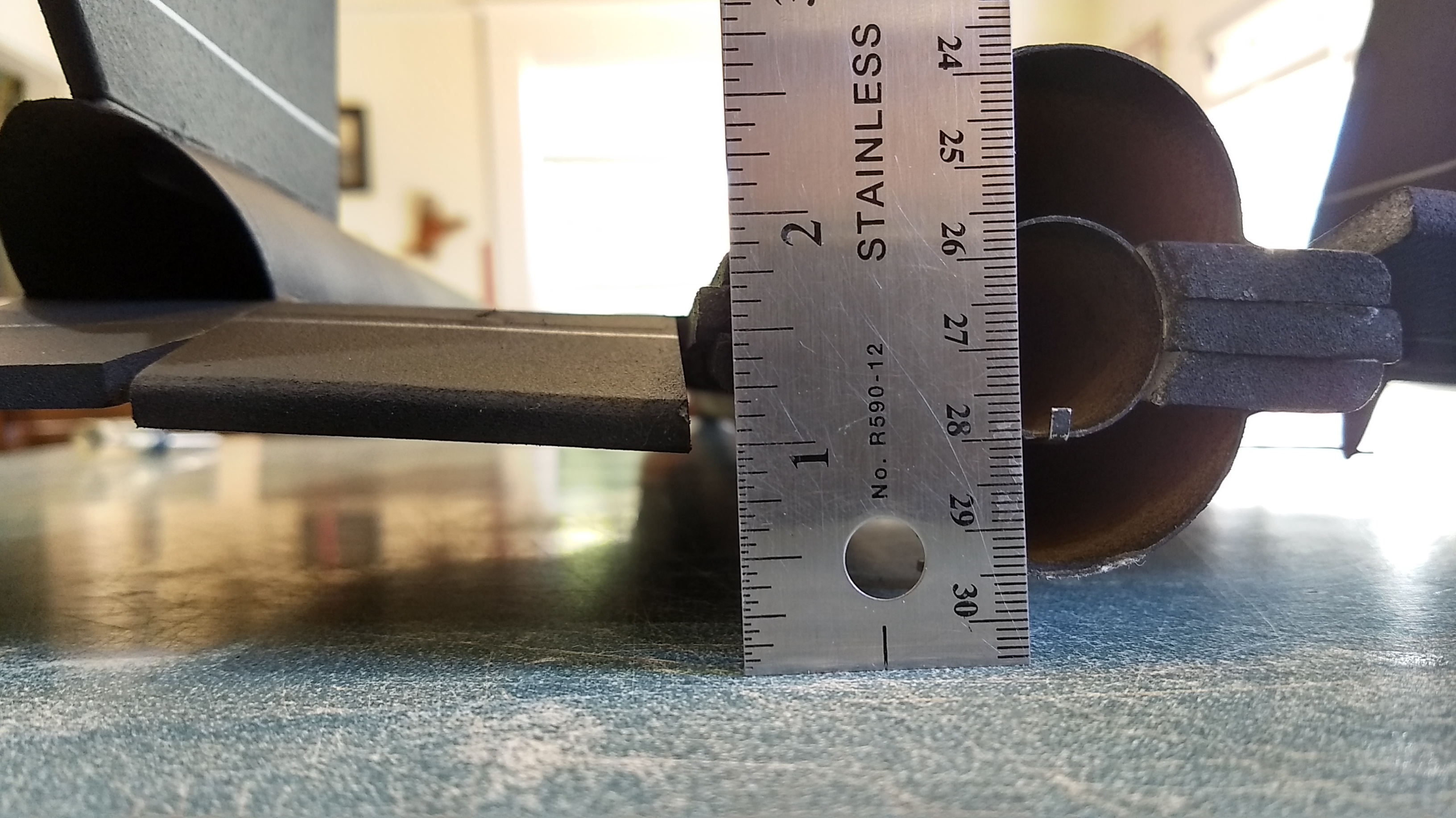
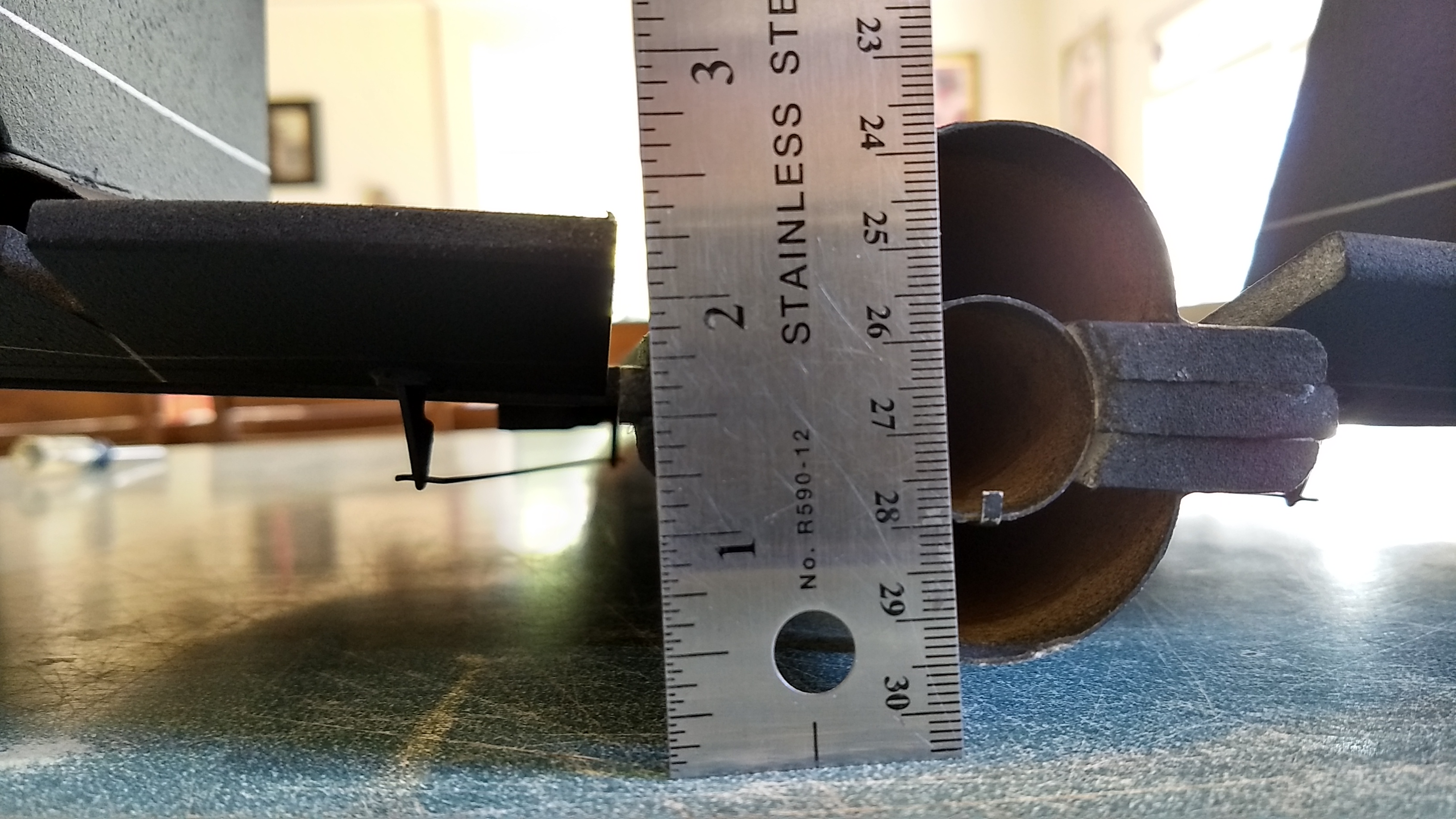
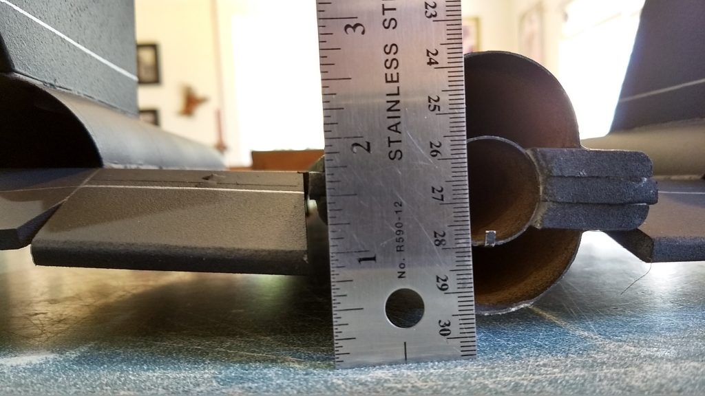
CG location for rocket flight: 1/4″ behind the the front of the nacelle tubes.
Note** If your kit includes plywood plates to attach the nose cone please refer to these instructions: INSTRUCTIONS
Unpacking your kit:
The kits are packed to protect them in shipping, but the contents are fragile so unpack carefully. Carefully cut the tape holding the tubes in the box, then unwrap/lightly cut the plastic wrap to free the tubes, the spar may be packed in the tubes and the baggie with the little parts and nose cone will be in the tubes as well. Carefully cut the tape holding the cardboard wing protector in the box and carefully remove it, don’t pull hard or bend it. Then carefully cut the tape holding the cardboard top piece to the bottom. There may be some sticky tape holding the cardboard to the bottom cardboard piece, carefully peel it being sure not to bend anything. Once the top cardboard is free you can see the foam wing/tail parts, there are little fragile pieces in here, so unwrap carefully. It may be best to use an exacto to lightly cut the plastic wrap and carefully remove it without cutting into the foam. Make sure everything is free before you remove the pieces to avoid breaking anything. Kits contain one or two scrap pieces for repairs if you damage anything in construction or flight, just cut and patch in a spare piece of the foam if needed using foam safe CA+.
Welcome to the world of rocket boosted radio control gliders. This is not a model for a novice RC pilot, but anyone who is comfortable with RC flying of an aileron controlled medium speed model should be fine. Read through the instructions, look at the photos and be sure you understand the step before commiting to cutting or glue.
Identify all pieces, the kit should contain:
1 wing taped together
2 vertical stabilizers
2 2.5″ long foam strips.
2 body tubes
1 nacelle tube(will be split and used for the right and left nacelles.
2 control horns w/pushrods
Velcro(for battery and rx/bec attachment)
3M blenderm tape
Upper and lower nose section
2 intake cones
Nose cone screw
motor tube with clip
long and short carbon spars.
1 landing skid.
2 rail buttons with t-nuts
Decals
Lead weight(can be self stick or lead shot)
Spare foam (for testing paint, glue, and sanding the edges to see how it behaves)
Assembly:
- This model was designed to use standard spektrum AR-400 receivers and 1s 500mah lipo stick battery. If you are using larger battery or receiver, you will need to plan the location ahead of time. You can notch the foam between the two body tubes to fit the receiver inbetween the tubes. If your battery is larger than the 1s 500mah stick battery, you can alternately put your nose weight back slightly into the body tube area and slot the foam between the two cones to allow you more room to fit the battery.
- Look at all parts and understand what pieces go where.
- The 3-d printed parts will need to be cleaned up a bit. The intake spikes should be cleaned of flashing and the flowthrough holes in the outer ring can be opened up with an exacto knife. The top and bottom cones will need the sprues sanded flush. The 3-d printed parts have a texture, you can use 220 grit sandpaper to smooth this and then you can apply acetone to a paper towel folded into about 1/4″ thick and saturated, just wipe the surface a bit and let dry. The foam has texture, and the sanded foam will have texture and the model will be panted flat black, it will never be a shiny model, so do as much as you feel is needed. I like a bit of the texture. Don’t over sand the surface as the surface is thin and the part is hollow with reinforcing inbetween the inner and outer skins, you can sand through these and leave holes if you are too agressive.
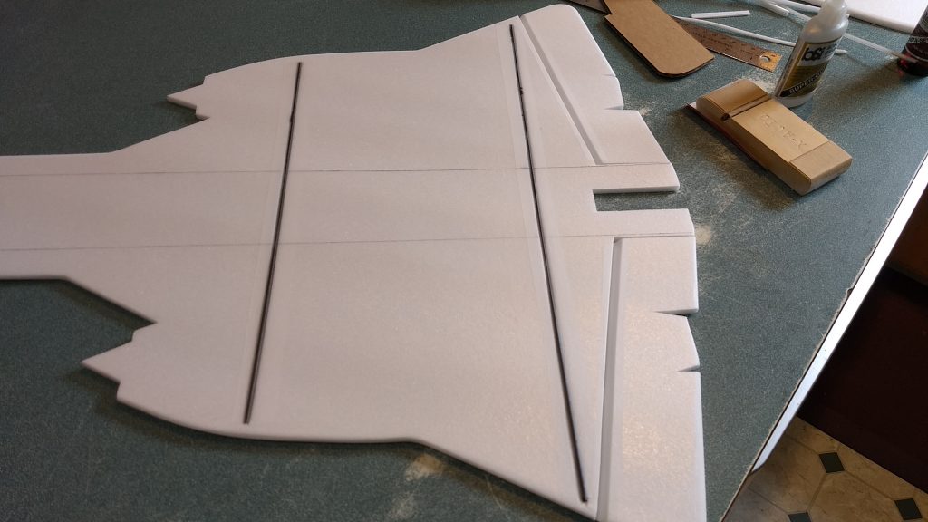
- Unfold the main wing and glue the taped joints. The forward joint is taped only on half of the cut so that it can fold to fit into the box, you can add a second piece of tape to support the cut before you glue the front fuse joint.
- Glue in the two spars into the premade slots on the bottom of the wing and then tape over with blenderm tape.
- You may use 220-320 grit sandpaper and a sanding block to round the edges of the foam before further assembly. Round all edges of the wing at this time except for the flat part where the intake cone will be mounted. Go slowly and take your time. Round the leading and trailing edges of the vertical stabilizers at this time as well. NOTE***The foam has a smoother side and a rougher side. I’ve created the wing and stabilizers so the smoother side is more visible so you will wind up with a more consistent finish when you paint
- Once the sanding is finished wrap blenderm tape around the edges and top of the forward wing joint, it will help support and hide the joint.
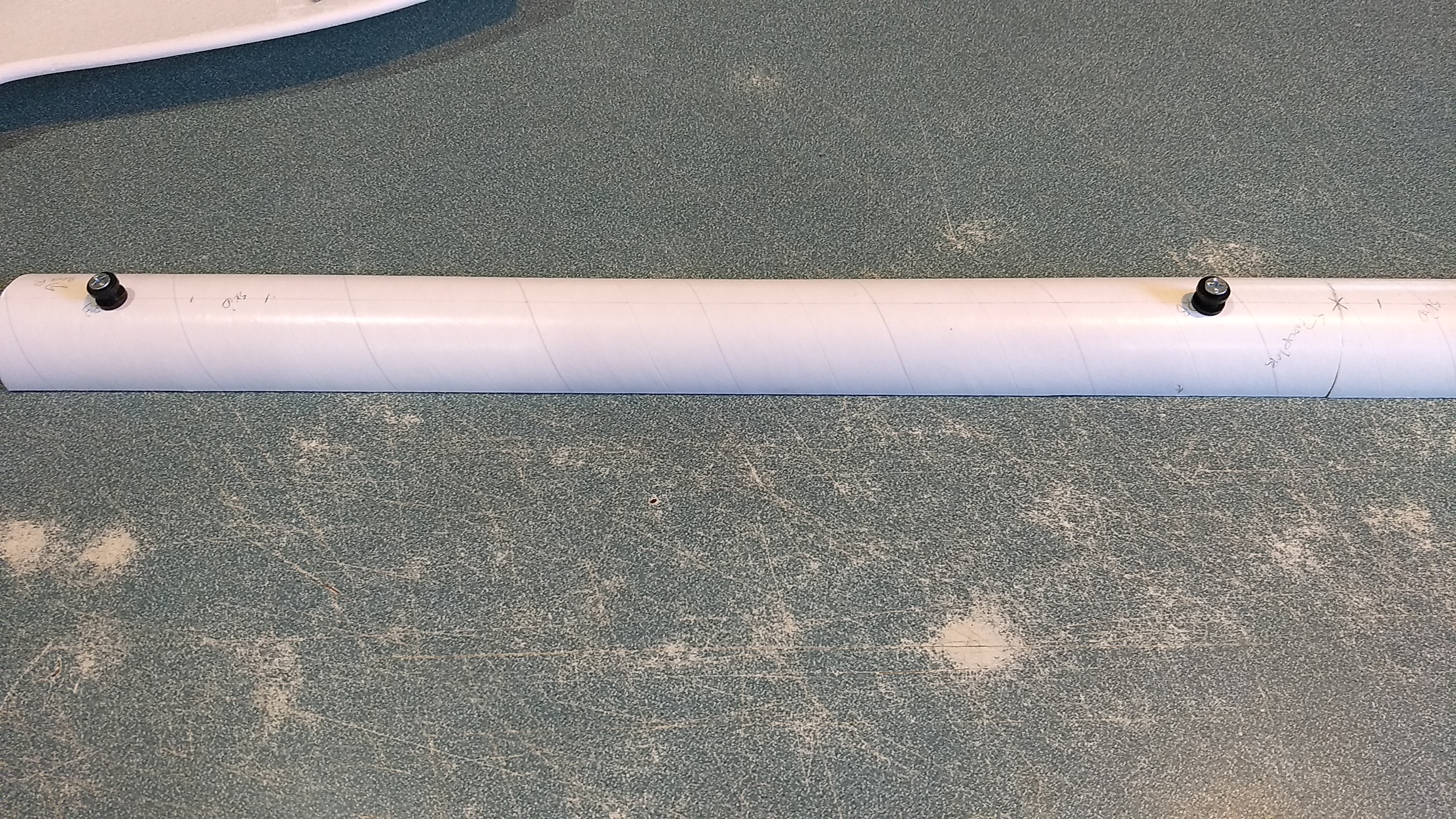
- Glue the two body tubes together with the foam safe CA+. The body tube is marked, make sure you align the two tubes so that the arrows are aligned so that the marking guides are correct.
- Once the glue is set, using an exacto knife, carefully using multiple light cuts slowly cut the body tube into two pieces. I found doing it slowly freehand took a little bit of time but if you go slow and make multiple passes a little at a time will yield the best result. you can sand the edge slightly if desired but the glue fillet will hide small gaps. Make sure you cut on the lines marked “cut”
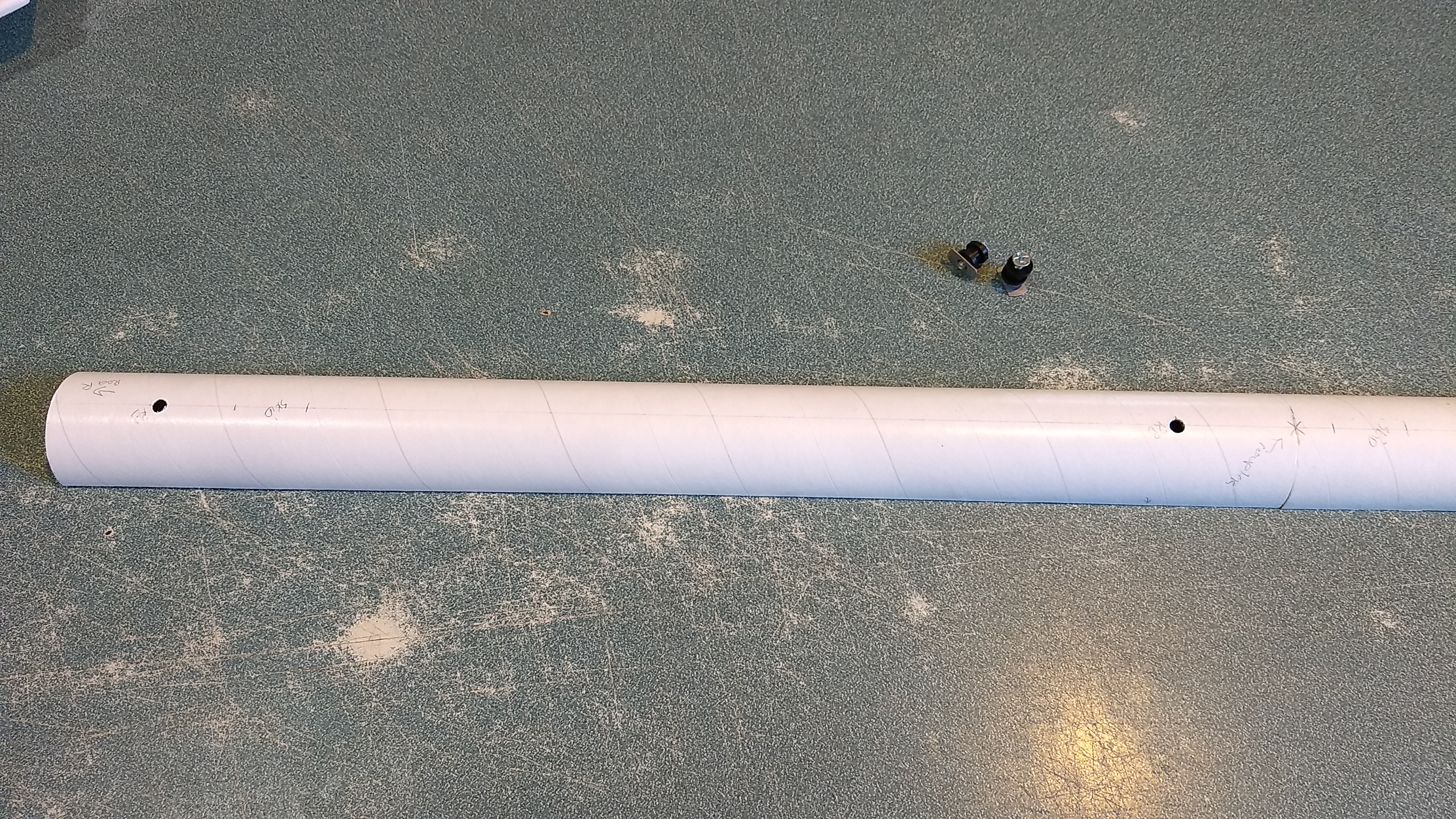
- On one of the tube halves there are marks for the rail buttons. This will be the bottom of the model. Cut holes as marked and install the rail buttons from the inside. If the rail button T nut flanges deform the tube, bend the flanges slightly with a pliers to allow them to contour to the inside of the tube.
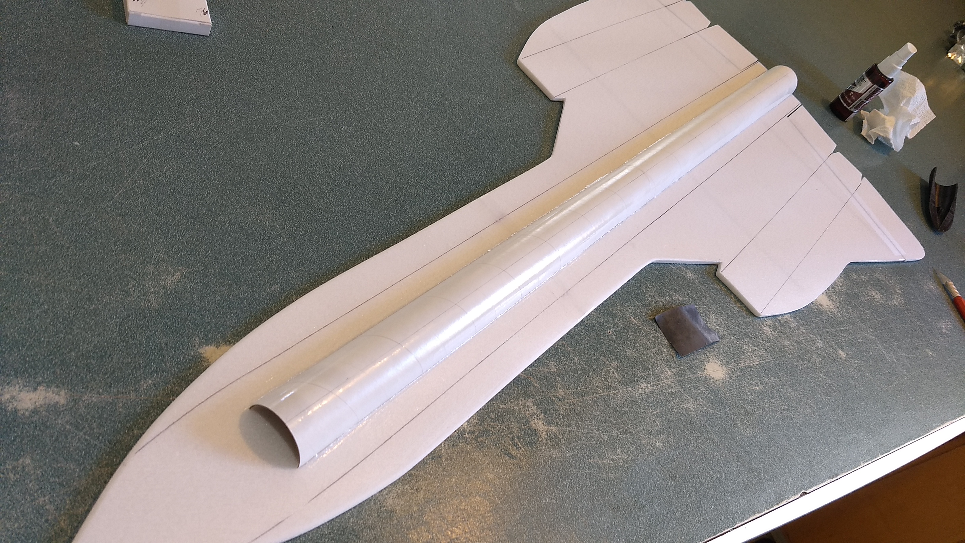
- Glue the top body tube in place on the wing keeping it straight and centered and even with the rear of the model . Start at the rear, do a little at a time on each side and make sure the front is centered. Use the top cone shoulder as a guide at the front to make sure the front is round and the cone shoulder will fit inside, as you do this, press it down onto the foam, the lug for the screw will make an indent in the foam. Remove the cone and cut through the foam at the indent so that the lug can pass through to the other side when the cone is in place.
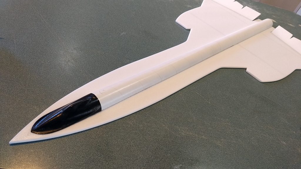
- Glue the top cone in place
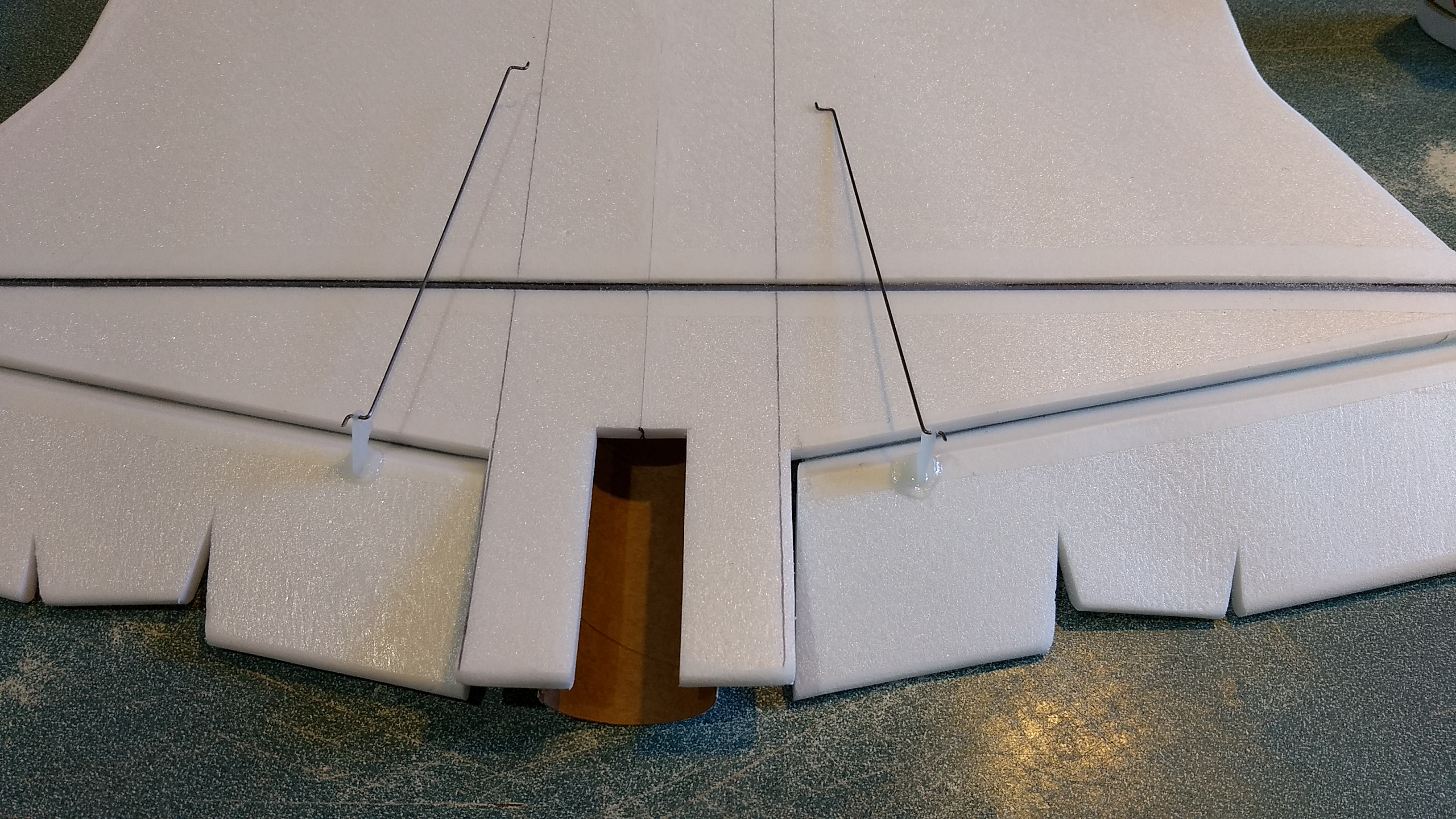
- Glue the two pushrods/control horns in the bottom of the wing in each control surface in the pre-punched holes using CA+. Apply CA+ to the top of the control surface on the prongs from the control horns to capture them in place. Set with accelerator. Note in the picture how the control horns face, the flat part of the control horns faces forward so that the holes that the pushrod go in are even with the hinge line.
- Your radio needs to be configured for Delta mixing, this means that the servo arms will move the same direction during elevator stick movement and opposite for aileron stick movement. Connect your servos to the receiver one in the aileron connection and one on the elevator connection and apply power. Use a servo arm at least 9/16” long and with holes small enough that there won’t be slop with the pushrod wire when installed. I use the hole furthest out on the servo arm, to maximize movement. On some servos there are a long two-ended servo arm, you can use this arm and trim off one end. Zero out any trim settings on the transmitter.
- Connect a servo to each pushrod. If the pushrod is too tight, you can use twist an X-Acto knife in the servo arm hole to make it larger, but be careful and do not make it too large. Note that the servo arm will be facing the center of the model so that the pushrod comes to the servo at a 90 degree angle from the hinge line. Once connected check control surface direction. Flip the model right side up and look at it from the rear. Moving the transmitter stick back(up elevator) should move both elevons up. Moving the transmitter stick to the right should move the right elevon up and the left elevon down. If you can’t get the servo reversing to give you the right polarity try swapping aileron/elevator inputs to the receiver or turning the servos over and swapping the servo arms to the other side of the output shaft. If that is correct insert the screw to hold the servo arm in place.
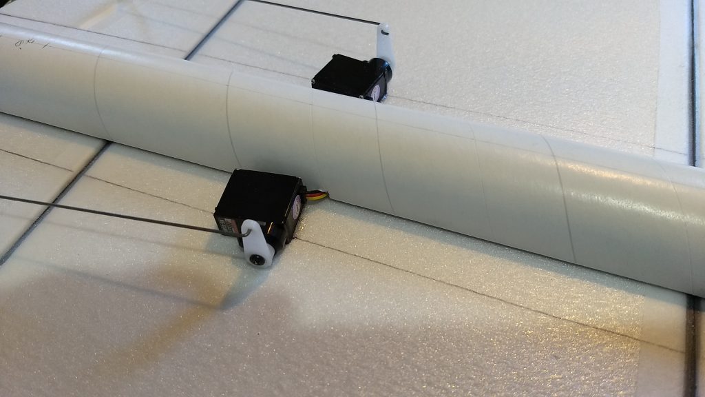
- Flip the model upside down. The servos may be attached to the model using double back servo mounting tape(not included) or by directly gluing the servo to the wing with foam safe CA+. Double back servo tape can loosen over time and with exposure to heat, I prefer to glue the servo in place. With the radio still on, put a moderate amount of glue on the servo, being careful not to get any near the output shaft, and set it in place on the model keeping the control surface centered. Do the same to the other side. Make sure the glue is set before continuing. Note** The servo electrical wire should point toward the front of the model, you want the pushrod to be perpendicular to the hinge line, use the bottom body tube half as a spacer guide to be sure the servos will not hit the body tube when it is glued in place. See the photo for an idea of how it should look. Tape the servo wires down toward the center of the model.
- I mounted my receiver upside down so I had to cut a hole in the center of the model so that the servo wires and battery wire will poke through the hole and allow the bottom body tube to be glued in place and not hit the receiver. If your receiver is large you can cut a larger hole in the wing and set the receiver into the recess completely. I inserted an 18″ servo extension into the throttle output and connected the battery wire to the other end and taped it down in the center of the model. The wire needs to be long enough so that the battery connector sticks out the front of the body tube for access. I taped down the antenna down the middle as well.
- Place the bottom tube on the bottom of the model with the rail buttons toward the rear and with the rear of the tube even with the rear of the model. Make a mark where the tube goes over the servo wires and cut small notches so that the body tube clears the wires.
- Carefully glue the bottom tube in place using foam safe CA+ and accelerator. Take your time and do a bit at a time, It is especially important as you get to the front where the cone shoulder needs to fit inside to use the cone as a guide at the front but be sure not to glue the cone to the foam.
- Test fit the bottom nose cone and screw and make sure you can lightly tighten it down and it is flush. The two lugs on the top and bottom cones for the screw should almost touch, but if the foam is a little thinner than normal and if the bottom cone will not sit flush you can sand the lug on the bottom cone that contacts the top screw lug a little at a time so that the bottom cone will sit flush. If you accidentally strip the screw hole add some foam safe CA in the hole and then when cured try screwing in again.
- Remove the bottom cone.
- Attach two of the weights in the marked area on the bottom of the fuselage/foam. Make sure they are far enough back that the nose cone will sit flush. You’ll use the third weight if needed for final balancing. If your kit came with lead shot, you will glue the lead shot to the underside of the bottom cone when you are balancing at the end.
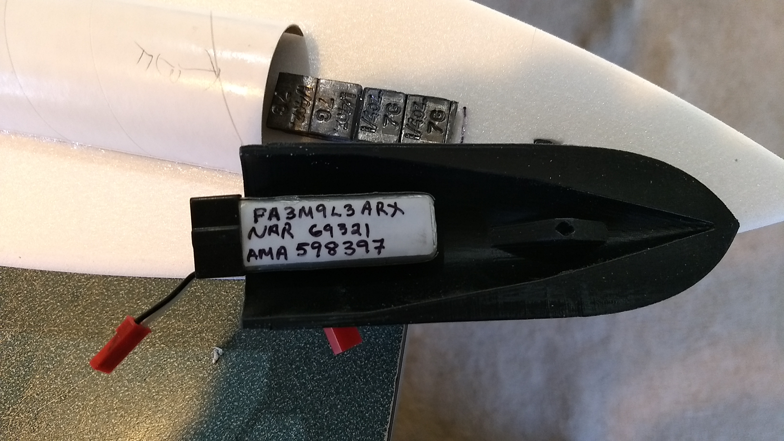
- Attach the flight battery using velcro to the top inside of the bottom cone, mount it to the rear of the cone so that it will allow the cone to sit flush.
- Find the short 2″ diameter pre-marked body tube with the slots pre-cut. Carefully cut the tube on both sides to make two halves using an exacto making multiple light small cuts, take your time. Using an exacto or scissors cut the rear angles as marked, these are needed to clear the elevon. Note the angles are not symmetric because the elevon is angled and the two sides need different angles.
- Flip the model over and lay one side of the wing on a table edge and supported so that it is flat.
- Look at the two pieces of nacelle tubing. There is a left and a right. They are marked on the tubes and the slot on for the vertical stab will be inward. If you have these swapped the elevon won’t have proper clearance to move.
- Glue the correct nacelle tube in place. The font of the nacelle tube is even with the front of the wing and the rear must allow the elevon to move fully. There is a line on each wing half for gluing the nacelle. IT IS CRITICAL the first edge is glued on the line otherwise the nacelles may not be straight and the vertical stabs will have an undesired rudder angle built into them!! Glue the other edge in place, at the front use an intake cone as a guide for the front of the tube to be sure it is round and will fit the intake cone. You can glue the intake cone at the same time, it will butt against the wing and recess into the nacelle tube. You may need to let the front of the wing hang over the table edge so that the intake cone will lay flat.
- Repeat for the other side. Use accelerator to set the glue as you go.
- Make holes and glue in the skid on the bottom of the model on the mark in front of the forward rail button. Make sure the skid is vertical and in line with the rail buttons. The skid helps protect the front rail button when landing on a runway.
- Glue the two foam 2.5″ long strips onto the motor tube. Note how they are on opposite sides and the motor hook is at a 45 degree angle to the strips. This to allow the motor hook to have clearance when you slide the motor tube in place in the rear of the wing.
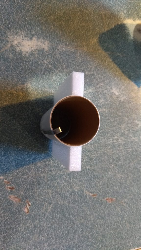
- Test fit the motor tube in place, sand the two foam strips a little at a time till the tabs will fit into the rear of the model with the tabs straight up and down. The sides of the motor tube are centered in the cutout in the wing. Note the motor hook is glued and taped at the front, make sure you slide the motor tube in so that the motor hook can move to release the motor, apply foam safe CA+ from the rear to secure it in place. The motor tube doesn’t need a lot of glue to hold it in place, the thrust of the motor is against the rear of the wing and the hook just keeps the motor from falling out after burnout.
- Glue the two vertical stabs in place in the slots. There is a smoother side to the foam, have that side outward. The foam has some variation in thickness and I’ve hand fit the left and right into their respective slots, if they fit too tight or too loose try swapping sides. If they have any curve to them, gently bend them in the opposite direction to straighten them out before gluing in place. The stabs angle inward, it isn’t critical the absolute angle just try to get both sides approximately the same. Reinforce the joint on both sides with a CA fillet on the inside and outside of the tube, use accellerator to set the glue before proceeding.
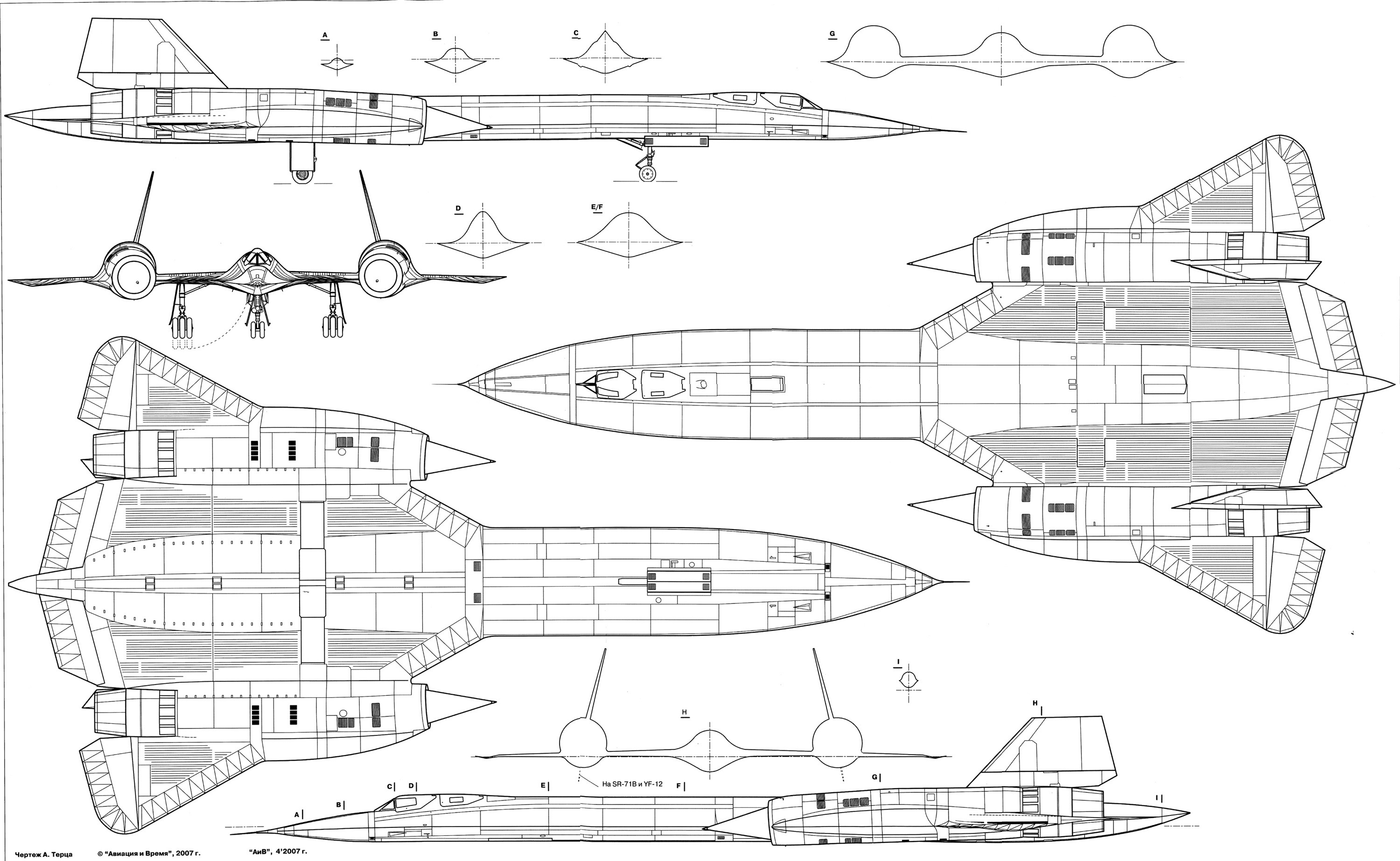
- Paint the model using ONLY testors or model master enamel spray paint. This is the only paint I recommend. I’ve used testors and model master flat black and testors silver enamel and they work fine. Mask off the rail buttons and the servo output arms to prevent paint from getting on them. Do not spray too close to the model. Use many light coats and do not spray heavy. I apply a coat to all the edges of the foam first since it tends to soak into the sanded exposed edges and look lighter, then apply light coats till the model is covered. Paint adds weight, use just enough to get a nice even finish. I used slightly more than one can of flat black to complete each prototype, and that added exactly 1/2 ounce to the model. If you want to use a black sharpie to apply panel lines they will leave an indent in the foam surface that will be visible after painting and adds a nice touch. Refer to the 3-views below for ideas.
- Once dry you may apply the markings. Carefully apply the markings and slowly roll the backing paper off as you apply pressure to the marking. Once applied, use a hot hairy dryer to soften the markings and press them down with your finger to set them into the paint and foam. You can use a silver sharpie to add panel lines or accents if you wish.
- Install your loaded motor.
- Support the model at the balance point indicated for boost. Add more weight as required to balance. If the model is nose heavy you may remove some of the lead weight that was installed. Do not try to fly the model too nose or tail heavy. Remember, a nose heavy model flies poorly, a tail heavy model flies once. My prototypes with the receiver mounted near the servos required the entire third piece of lead weight. The one prototype I build with the receiver forward with two servo extensions required half of the third piece of lead weight, but the servo extension added a quarter ounce so the final weight was exactly the same. If your kit came with lead shot, glue it into the forward part of the bottom cone using just as much as needed for balance.
- Set up your throws and trims: The model uses approx 5/8-3/4″ up and down elevator throw and 1/2″ left and right aileron throw. It is quite roll sensitive on boost so you may tone this down as needed. For boost I used zero control trim but you may need some depending on how your model is built, and for glide I’m using about 3/16 of up trim or a slight bit more. I put this trim onto my flap switch so that I can go from boost to glide trim with the flip of a switch. Make sure when you launch you are in boost trim or it will be a very short flight.
Flying: Be ready on the first few flights to keep the model straight till you have the trims set perfectly for boost and glide. Try to do initial flights in dead calm conditions. You need to be ready to react quickly to keep it boosting straight up or slightly away from you. Keep the wings level. Count to 7 and start to push the model over level as the motor burns out and it slows down. Then click in the up trim. Once in a glide, if the model wags the wings it is getting too slow so push the nose forward slightly or reduce your up trim. Avoid drastic bank angles which cause you to lose altitude and make it easy to lose orientation. Gently fly around, and set up for landing into the wind when about 100′ high. The model will rock the wings if you start to get too slow, if this happens push forward on the stick slightly. The decent rate is very predictable, note the angle it is coming down at and head into the wind, keep some speed up so you don’t stall, and keep the wings level as it decends and gently flare just before touchdown. Try not to flare early and stall the model.
-
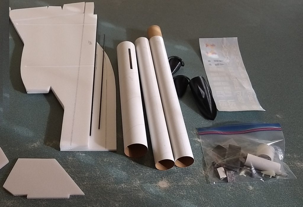
- Kit Parts

-
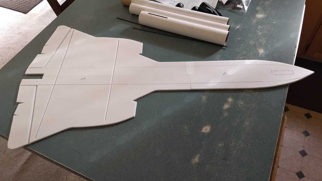
- Unfold the wing and glue the taped joints

-
- Glue in the two spars then tape over them with the blenderm tape.

-

- Sand the edges round, then tape around the forward wing joint.

-
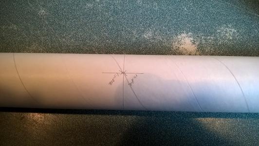
- Join the two body tubes so that the alignment arrows are aligned.
-
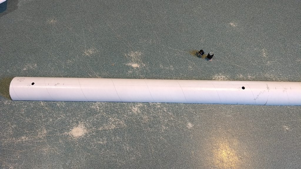
- Cut the body tube in half, make holes as indicated for the rail buttons
-
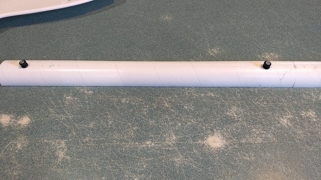
- Install the rail buttons.
-

- Install the upper body tube half so that it is centered and flush with the rear of the model.
-
- Use the upper nose cone shoulder as a guide to make sure the front is round the cone will fit inside.
-
- As you check that the front cone fits into the body tube as you glue the tube in place, push the top cone down into the foam to make an indent where the screw lug will go.
-

- Cut out the foam so that the screw lug can pass through, then glue the top cone in place.
-
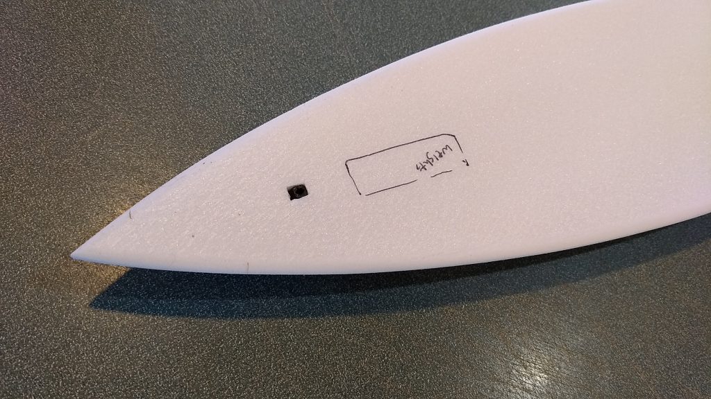
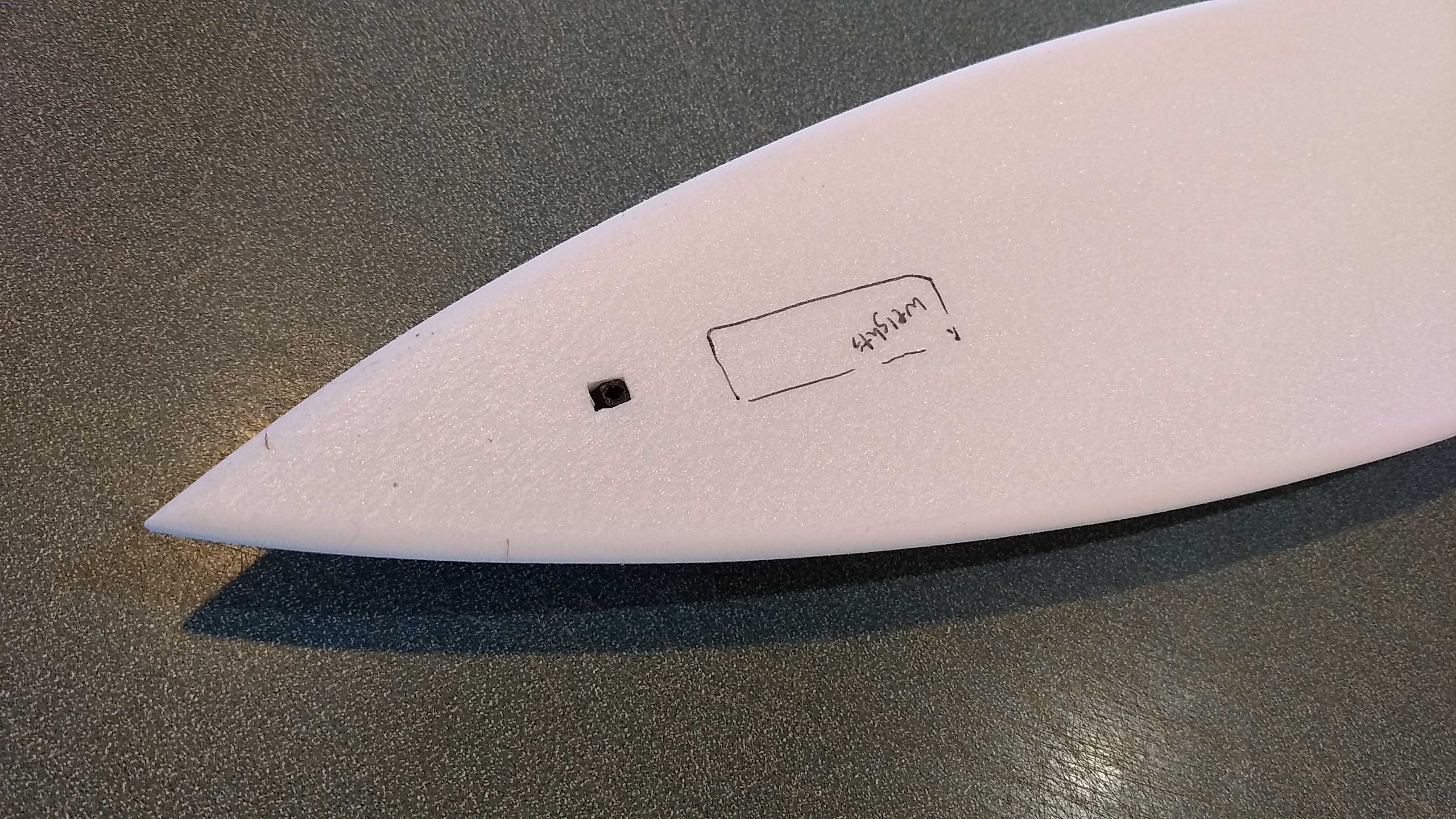
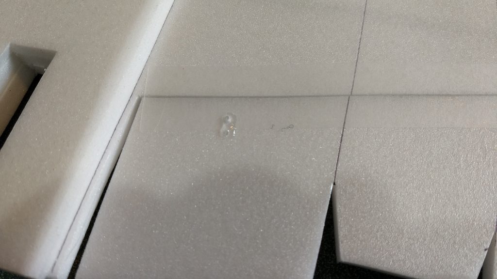
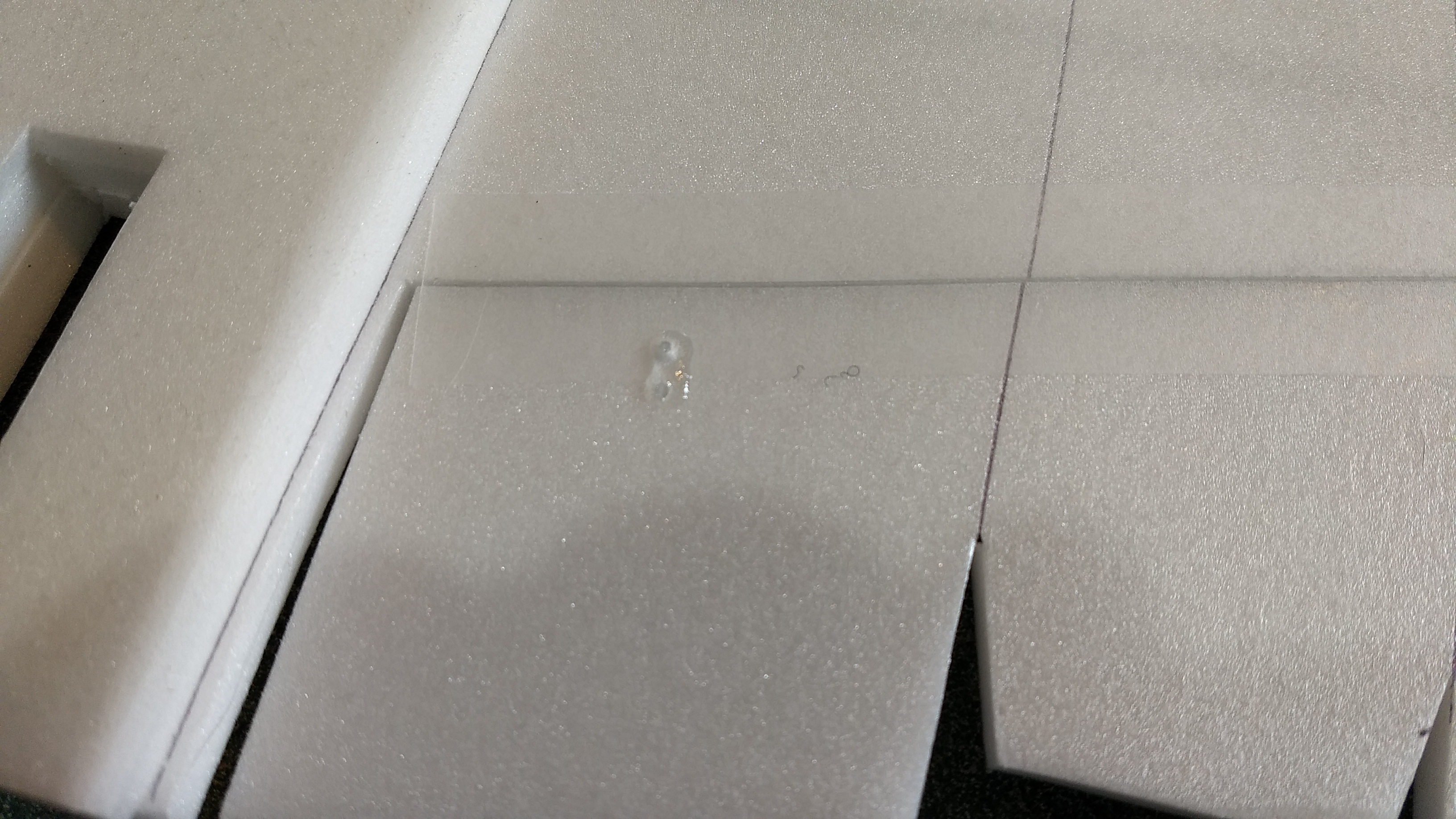
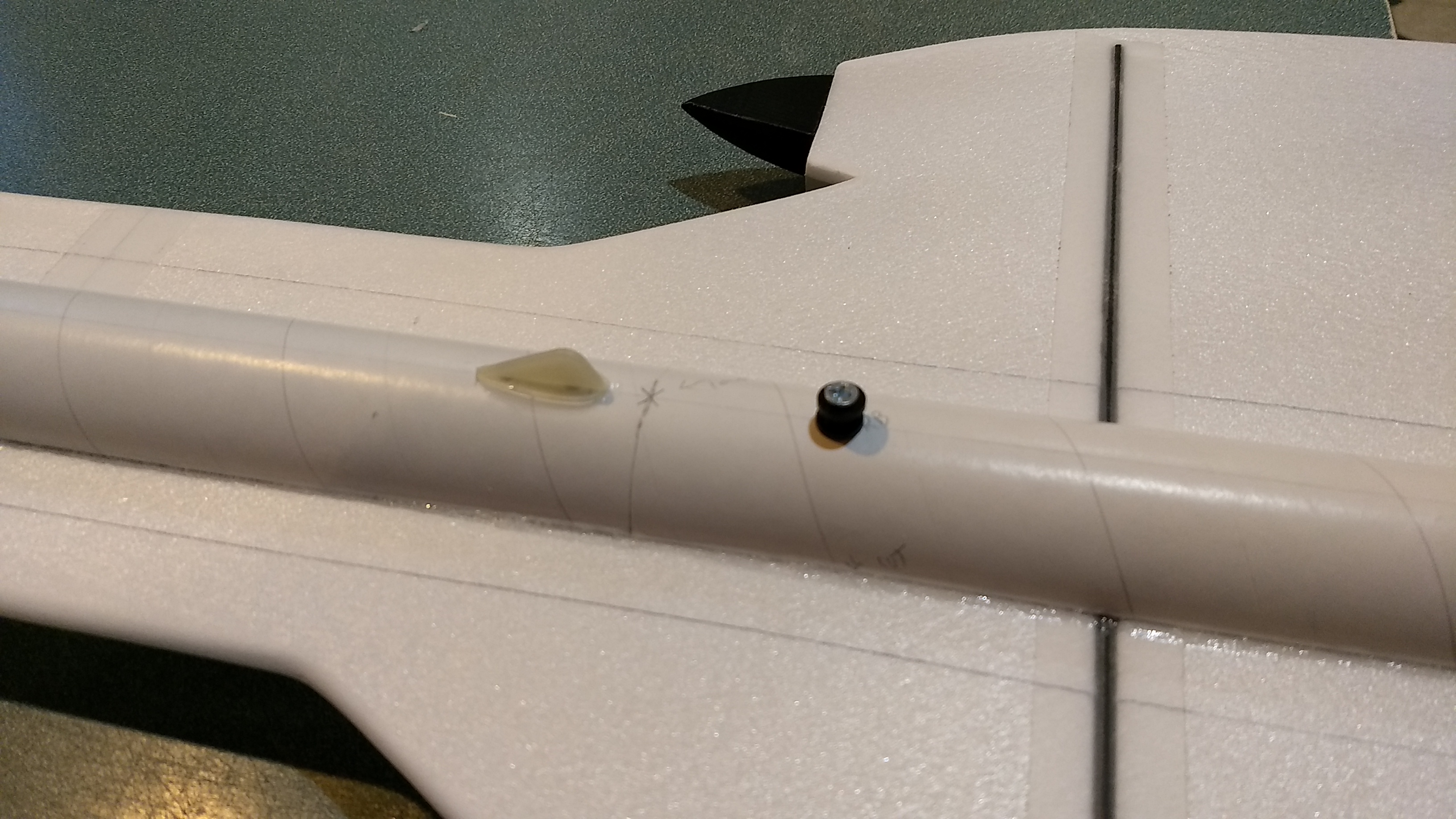
- View of the bottom of the fuse showing the screw lug from the top cone coming through the foam and the marking for the lead weights.
-
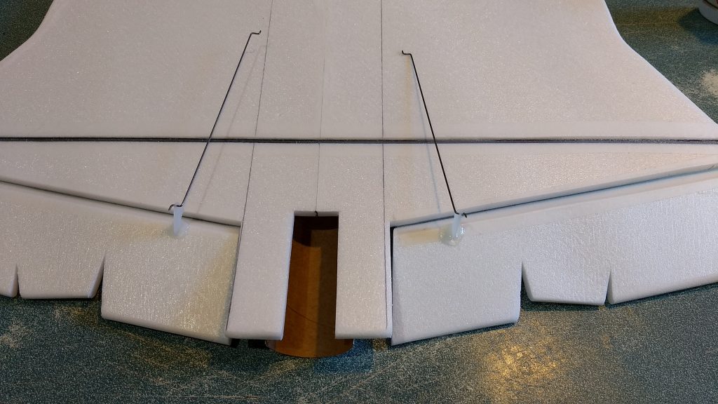
- Glue the pushrod/control horns in place into the pre-made holes and then apply CA+
-
- Put a drop of CA+ on top of the control horn prongs to lock them in place.
-
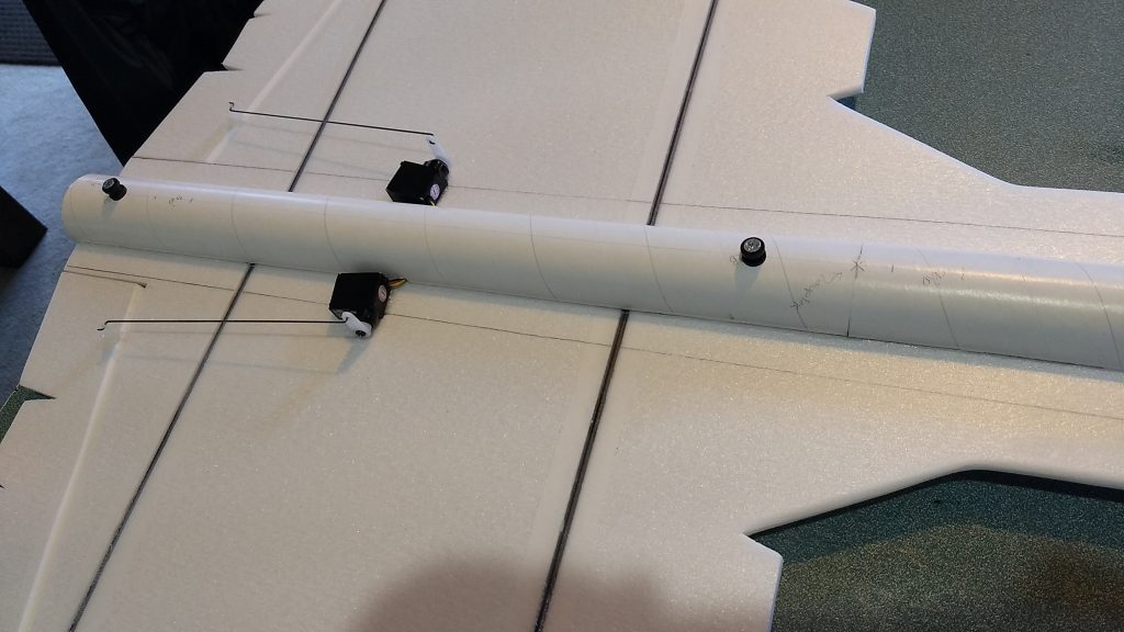
- Glue the servos next to the body tube.

-

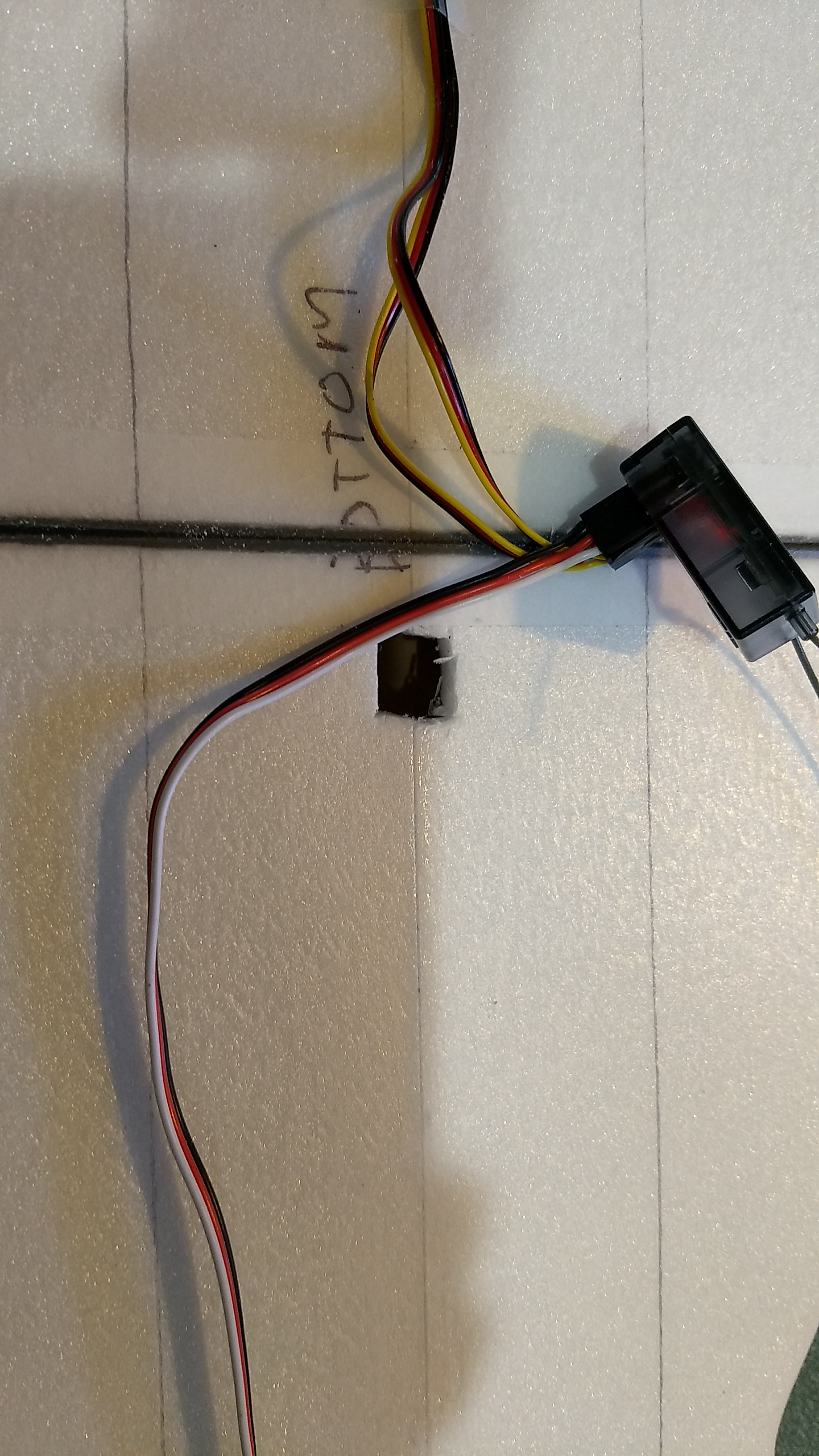
- Cut a hole in the center of the wing for the servo wires/plugs to fit down into so that the receiver sits low enough so that the body tube will clear it when glued in place.
-
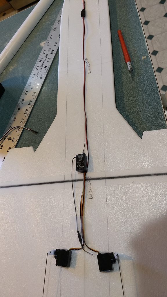
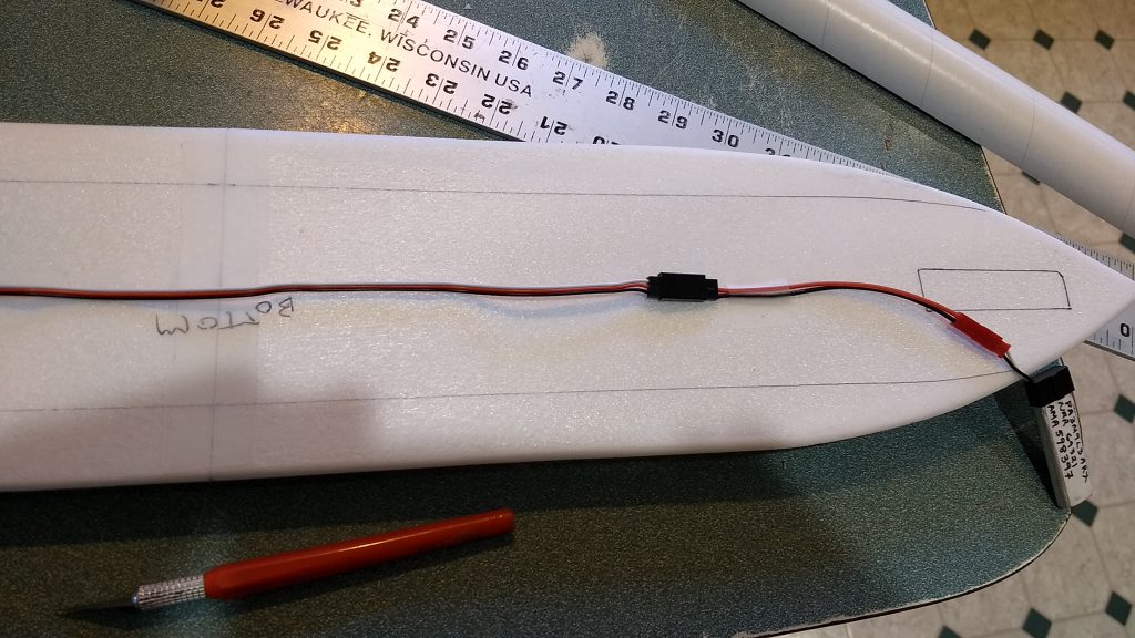
- Attach a servo extension into the throttle channel and route it forward and connect to the included battery wire adapter.

-
- Tape down the wiring and and antenna

-
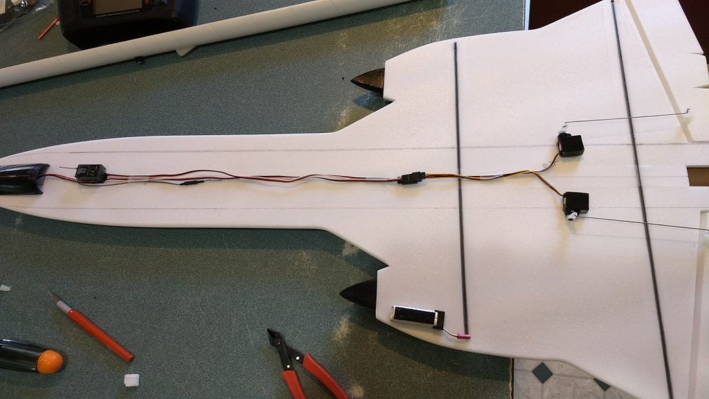
- Alternately putting receiver further forward with servo extensions, gets servo weight up forward at the cost of extra servo extension, may reduce nose weight needed, but be a wash in overall weight.

-
- Cut slots for the servo extensions and route them into the body tube and forward out the front.

-
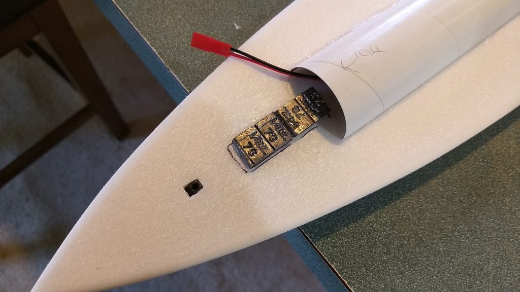
- Nose weight added in marked location on bottom of fuse, you may need to add more when you do final balancing after painting.

-
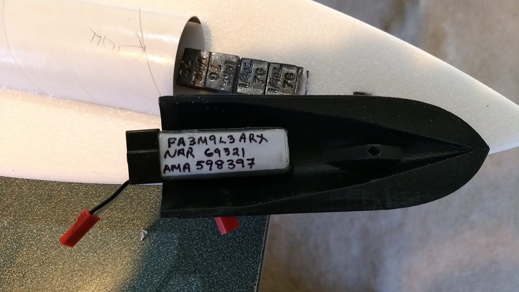
- Secure the flight battery into the upper rear of the cone, making sure it will clear the lead weights and sit flush.
-
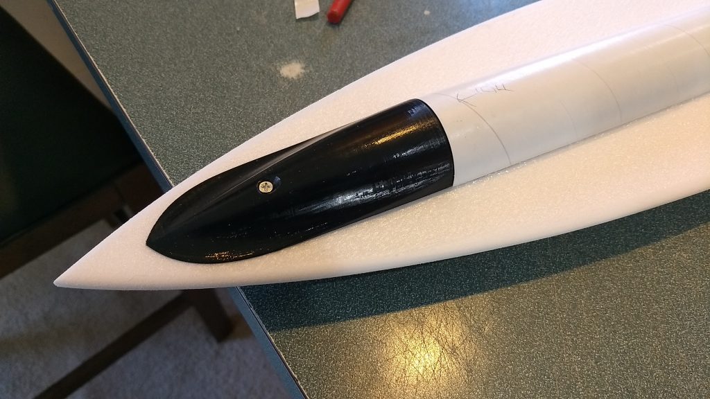
- Secure the bottom cone with the screw.

-

- Install the two nacelle tubes following the directions exactly.
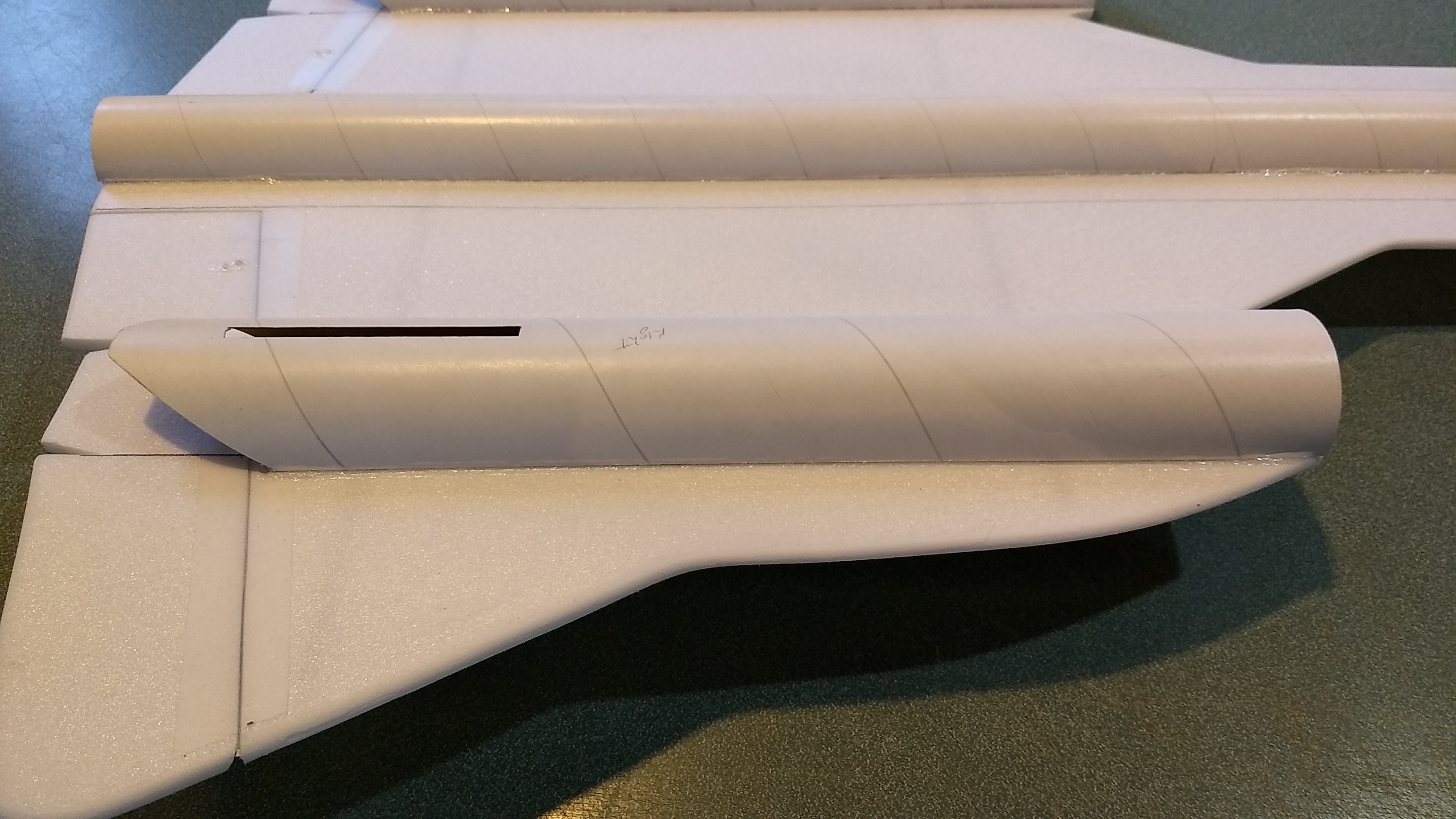
-
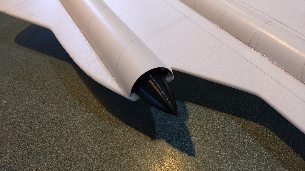
- Use the intake cone as a guide when gluing the front of the nacelle.

-
- Glue the two foam strips onto the motor tube, Motor hooks are no longer used.

-
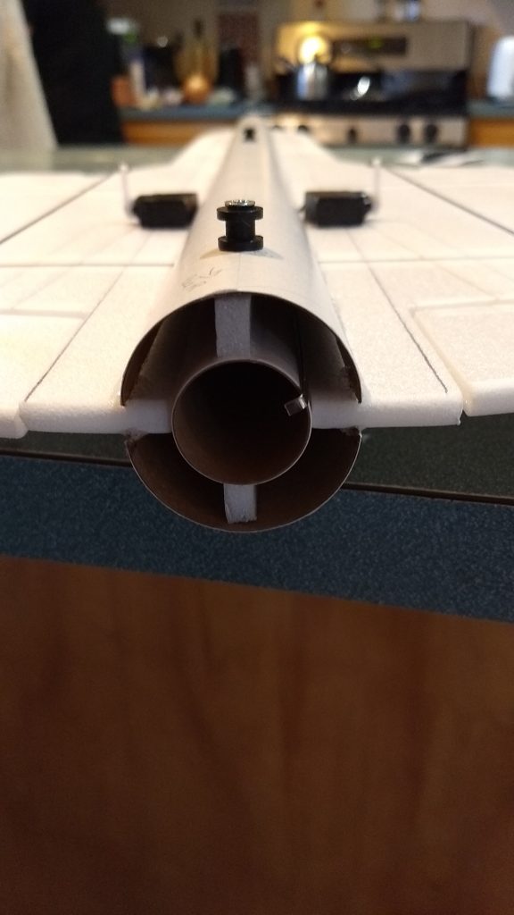
- Fit the foam tabs and then insert the motor tube from the rear into the slot in the wing, glue in place when correct.

-

- Install the front skid
-

- Install the two vertical stabs, note how they angle in, the actual angle isn’t critical but should be approx the same on both sides.
-
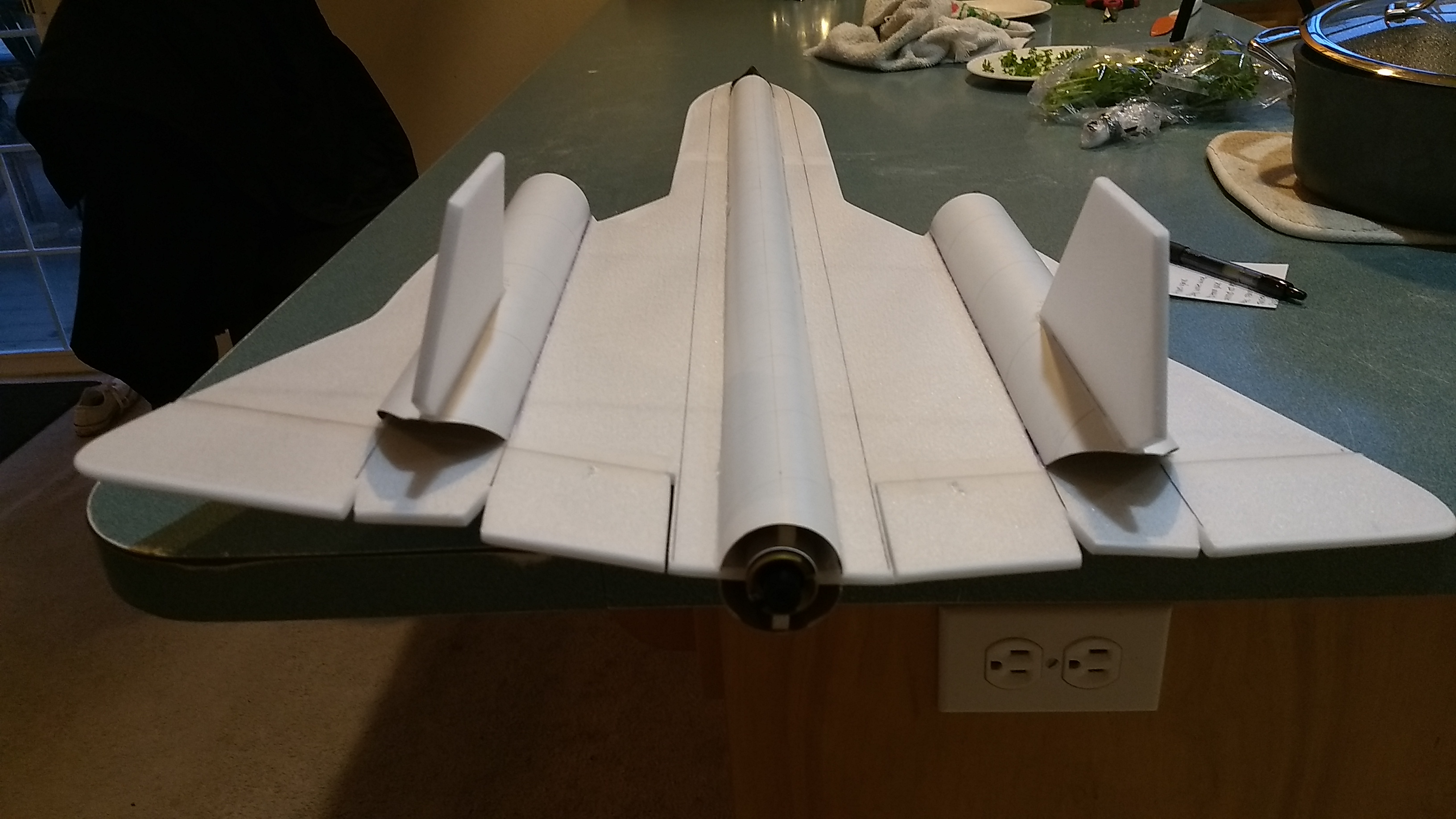
- Front view of completed model, on this version I added panel lines with a black sharpie to indent the foam, they are visible after painting seen in the A-12 version

-
- Neutral boost trim
-
- Glide trim

-

- Left Aileron
-
- Right aileron
-

- Up elevator
-
- Down elevator

-
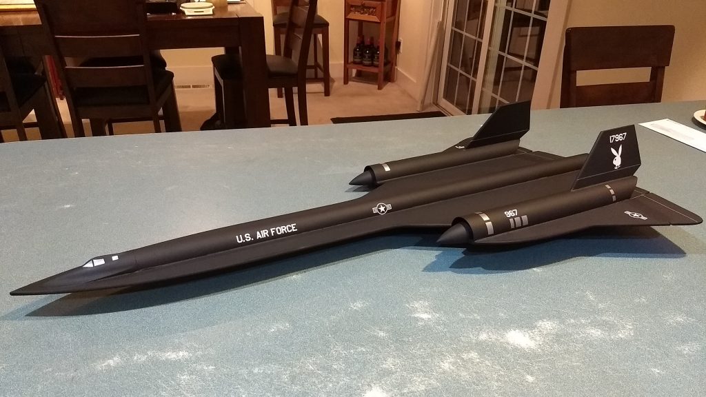
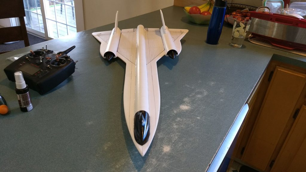
- Completed model

-
- A-12 single cockpit version

-
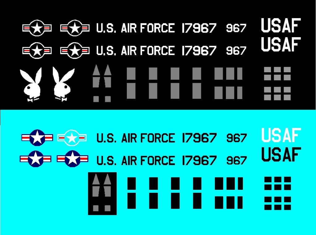
- Upper set is the current kit decal set, lower set for the A-12 silver upper version with alternate colors available direct from stickershock23

-

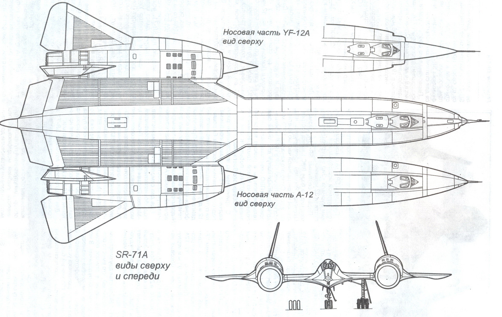
- 3-view showing panel line details
-
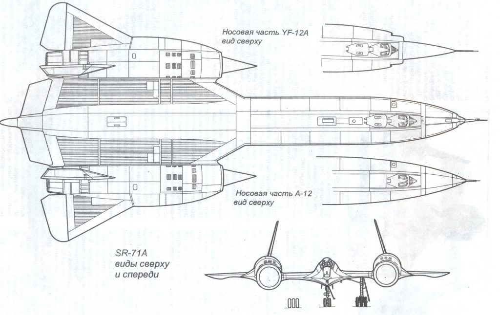
- Top view showing A-12 and SR-71 nose differences