The Dragonship RC Rocketplane kit calls back to early sci-fi styling. It also looks great decorated as a WW1 German or Allied aircraft! It comes with a plastic nose cone, 2.6″ white tubing for the body, 6mm depron wing and tail surface. Spars are pre-installed and rail button holes are pre-punched. Construction is very simple and takes about an hour and a half. Please refer to the General information for all kits tab above, then read these instructions completely before starting assembly. Length 31″, wingspan 23″, weight 250 grams(8.9-9.6 ounces) rtf. High quality cut vinyl decals available from stickershock23 HERE
CG location for rocket flight: 9 3/8″ forward of the trailing edge of the wing at the center with battery and loaded motor installed ready for flight.
Unpacking your kit:
The kits are packed to protect them in shipping, but the contents are fragile so unpack carefully. Carefully cut the tape holding the tubes in the box, then unwrap/lightly cut the plastic wrap to free the tubes, the spar may be packed in the tubes and the baggie with the little parts and nose cone will be in the tubes as well. Carefully cut the tape holding the cardboard wing protector in the box and carefully remove it, don’t pull hard or bend it. Then carefully cut the tape holding the cardboard top piece to the bottom. There may be some sticky tape holding the cardboard to the bottom cardboard piece, carefully peel it being sure not to bend anything. Once the top cardboard is free you can see the foam wing/tail parts, there are little fragile pieces in here, so unwrap carefully. It may be best to use an exacto to lightly cut the plastic wrap and carefully remove it without cutting into the foam. Make sure everything is free before you remove the pieces to avoid breaking anything. Kits contain one or two scrap pieces for repairs if you damage anything in construction or flight, just cut and patch in a spare piece of the foam if needed using foam safe CA+.
Welcome to the world of rocket boosted radio control gliders. This is not a model for a novice RC pilot, but anyone who is comfortable with RC flying of a medium speed model should be fine. Read through the instructions, look at the photos and be sure you understand the step before committing to cutting or glue.
Identify all pieces, the kit should contain:
1 Wing taped together
1 Nose Cone
1 vertical stabilizer
2 control horns/Pushrods
1 Body Tube or (two body tubes and a coupler)
24mm Motor mount
3 13/16″ x 2.5″ wide strips to center the motor tube
Velcro(for battery and rx/bec attachment)
Lead weight
Notes before starting:
Foam safe CA+(Bob smith super gold + is good) is the only glue recommended for construction. You will also need foam safe accellerator to set the glue.
You may use 320 grit sandpaper and a sanding block to slightly round the edges of the foam if you prefer before gluing the wing and vertical stab in place, or use an exacto knife to cut a light bevel on the leading and trailing edges of the wing and stabilizer. Do any sanding before assembly.
Assembly:
- Glue three 2.5″ long foam strips on the motor tube using foam safe CA+. These help center the motor tube in the body tube once you insert it into the body tube. Note the tabs will be on the sides and bottom of the tube, the fin tab will make contact on the top of the tube. Refer to the picture. Use a small piece of tape on the motor to keep it from falling out after burnout.
- If your kit came with two body tubes and a coupler, install the rail buttons into the pre-punched holes at this time, then join the two tubes using the coupler keeping the arrow marks on the two tubes aligned. If your kit came with a single tube don’t install the rail buttons yet.
- Glue the vertical fin into place. Make sure the vertical fin is straight up and down using a triangle or something similar. Apply a light filet to both sides of the vertical stab on the inside and outside of the body tube.
- Test fit the motor mount into the body tube and under the fin tab. Make sure it fits, or sand the foam tabs lightly. Glue the motor tube in place, it will inset about 3/4″ from the end of the body tube. Put a fillet on each side of the motor mount tabs and fuselage. Do not glue the vertical stab to the motor tube yet.
- Apply CA+ to the taped wing joint, and apply CA in a squiggle pattern about 1/2″ on either side of the wing joint and on either side of the pencil mark on the body tube.
- Lay the wing over the body tube upside down, and make sure the rear of the wing at the center joint is even with the rear mark on the body tube. Make sure the line drawn lengthwise down the tube is aligned with the center of the wing joint. Keep the vertical stab vertical as the wing dries. The wing probably won’t touch the table tip so just try to keep the wing about the same amount above the table on both sides while the joint dries. Hold the wing in place till the glue sets. Use accelerator to help set the glue.
- Once set flip the model over. Apply a fillet of glue on the wing/body tube joint, I put a blob of CA about every inch or so the full length and it will wick into the joint, use accellerator to set it and make sure it is set before you continue.
- Now block the wing tips up the same amount and check that the vertical stab is still vertical, if not adjust till it is, then glue the internal fin tab to the motor mount to lock it in place. This is not critical that it is exact just as close as you can, if the motor tabs are not perfectly aligned with the fin tab, that’s ok, it’s better that the stab is perpendicular to the wing.
- Apply CA+ to one of the control horns and press it in place on the top of the control surface in the pre-made holes. Note The control horn holes face forward and the pushrod should be closest to center of the wing. Repeat for the other side. Apply a fillet around the control horn on the the prongs on the top of the wing to lock them in place. See photos.
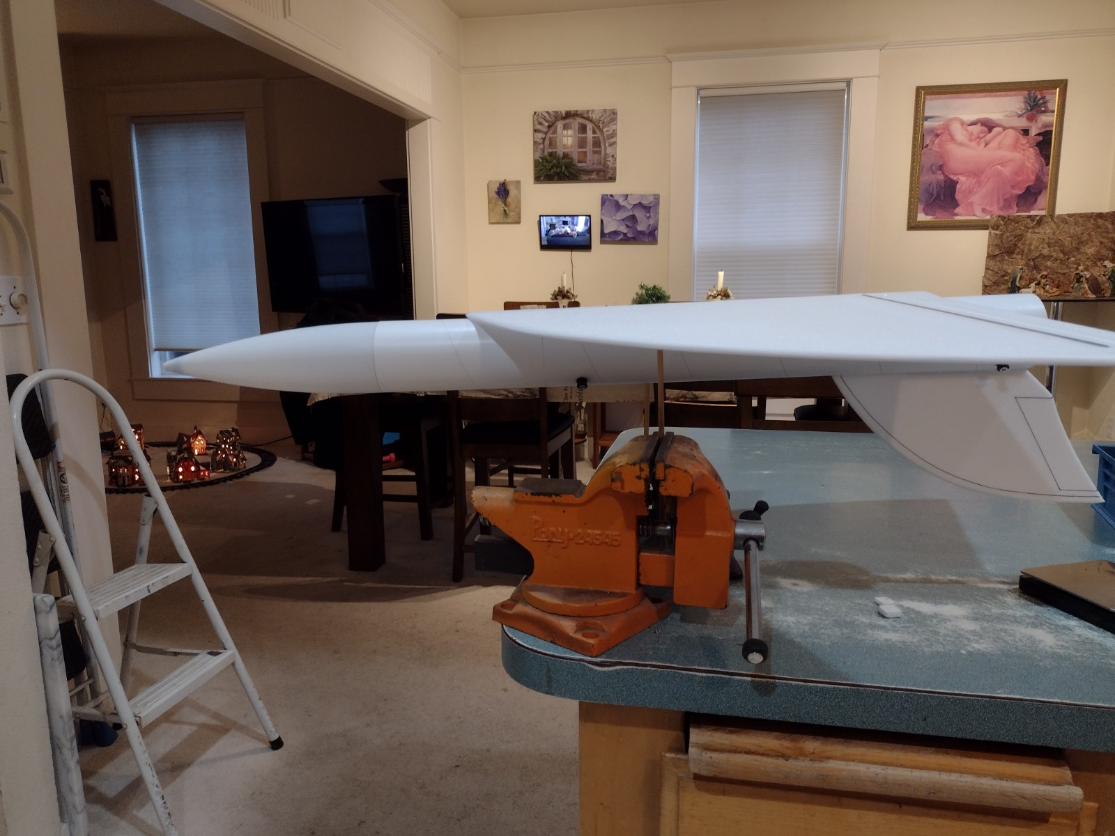
The basic construction is now complete.
Radio Installation
Note: Your radio needs to be configured for Delta mixing, this means that the servo arms will move the same direction during elevator stick movement and opposite for aileron stick movement. Connect your servos to the receiver one in the aileron connection and one on the elevator connection and apply power. Use a servo arm at least 9/16” long and with holes small enough that there won’t be slop with the pushrod wire when installed. I use the hole furthest out on the servo arm, to maximize movement. On some servos there are a long two-ended servo arm, you can trim off one end and use that arm to get sufficient length. Zero out any trim settings on the transmitter.
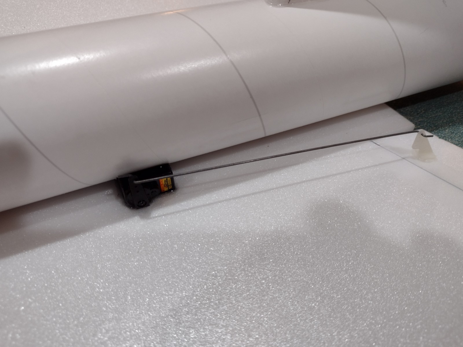
- Connect each servo to a pushrod. If the pushrod is too tight, you can use twist an X-Acto knife in the servo arm hole to make it larger, but be careful and do not make it too large. Tape each servo in place so that the control surfaces are centered and the servo is against the body tube. With the model right side up look at it from the rear. Moving the transmitter stick back(up elevator) should move both elevons up. Moving the transmitter stick to the right should move the right elevon up and the left elevon down. If you can’t get the servo reversing to give you the right polarity try swapping aileron/elevator inputs to the receiver or turning the servos over and swapping the servo arms to the other side of the output shaft. If that is correct, continue.
- Mark the body tube to cut a pocket that will fit each servo.
- Cut out the pockets and test fit the servo will go in and the control surface will stay centered. Adjust the pocket as needed.
- Attach an 8-12″ lightweight servo lead to each servo.
- Route each servo wire into the pocket on each side and route it forward and connect to the receiver and connect the battery and turn the radio on.
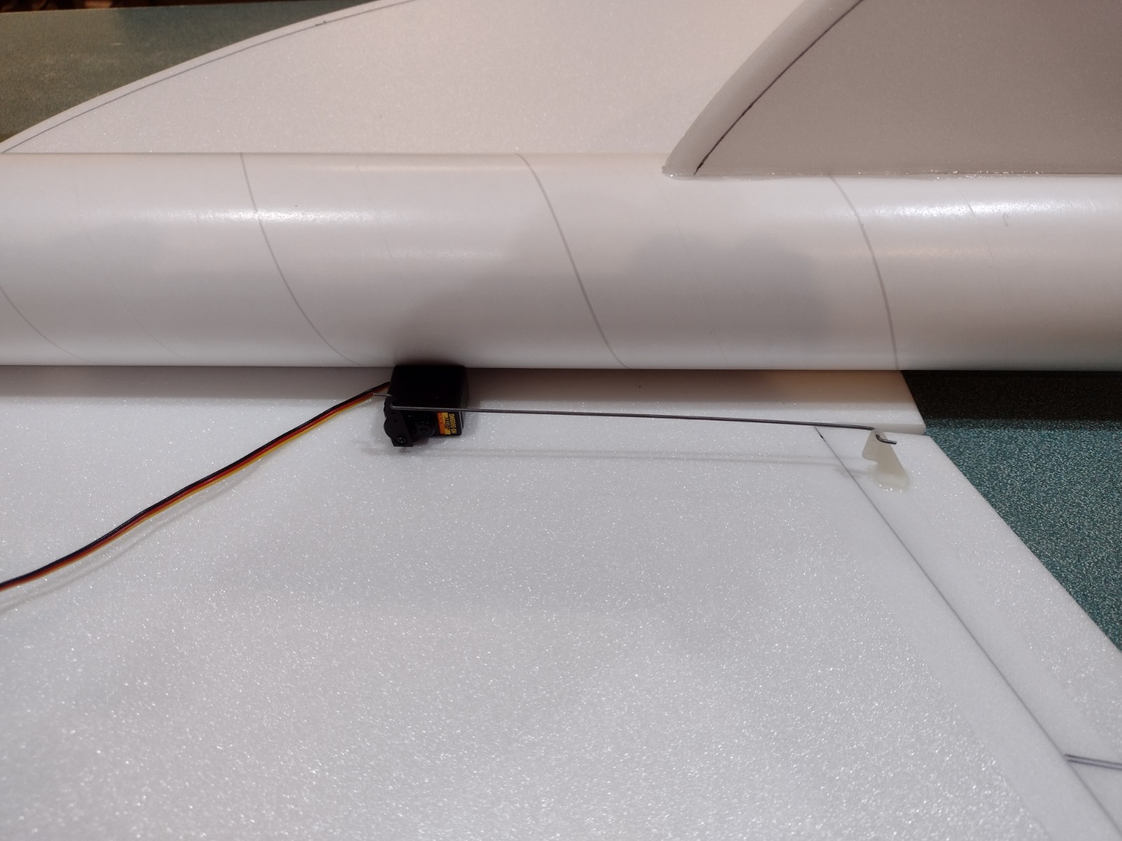
- Put a small amount of CA on each servo and glue it in place into the pocket and against the wing surface as far in as it will go. Put a small fillet of glue around the servo where it hits the wing and make sure it is glued and set before continuing. Keep the control surfaces level as the glue cures.
- Make sure the control surfaces are centered, use trims if needed. Now measure the control surface movement. Full elevator movement should be 1/2″ in each direction, aileron movement should be 3/8″ in either direction. When setting the control surfaces for neutral use the middle of the wing as your guide for what is level.
- If you have a flap/elevator mix you can program up elevator trim for boost and glide. If you can’t set the up elevator trim to a switch on your radio you’ll have to manually put in boost and glide trim using the trim tabs which is hard to do while flying the model. My model needed approximately 1/4″ of up trim for glide.
- Use the included Velcro to attach the receiver insde top of the nose cone. This allows you to be able to remove and replace the receiver if needed for repairs or for removing the servo wires.
- I attached the battery inside the nose cone on the bottom of the shoulder with velcro.
- Paint schemes: If you decide to paint your model, I can only recommend testors/model master enamel spray or krylon short cuts spray enamel at this time, others I’ve tried damage the foam surface.
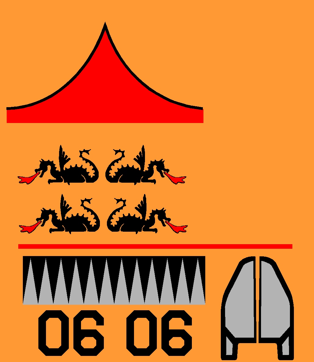
- If you go with the Sci Fi Dragonship style you only need to paint the nose cone gloss red with any brand of plastic safe paint. Pick the Dragonship decals.
- If you decide to do the Red German style, you will mask off the nose, tail and 5″ wide stripe on each wing and then paint the model red. Pick the German Iron Cross Decal set and use the White band decal for the front of the body tube.
- If you decide to do the white German no painting is required. Pick the German Iron Cross Decal set and use the red band for the front of the body tube.
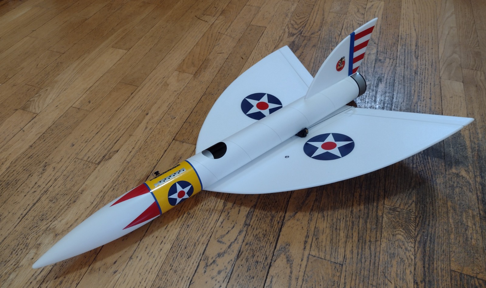
- If you decide to do the WW1 US scheme there is no painting required, pick the Peashooter set. I did add a few extra accents on the nose and tail just for fun, those can be hand painted or ask stickershock for some scraps of red and blue for you to use.
- If you choose to use the stickershock markings look at the completed photos to see where they go, after application use a hair dryer on hot to warm the markings and them push them down into the foam surface with your finger. They will really conform and stick down well.
- Use the pictures as a guide for where the decals go.
- Once decals are placed, trim out the pre-cut holes for the rail buttons that the vinyl covered and install them now.
- Install your battery.
- Insert your heaviest loaded rocket motor into the motor mount
- Support the model upside down at the balance point indicated for boost. Glue supplied lead weight in the nose or tail as needed to balance it. Do not use all of the lead, just as much as needed. Balance the model after paint and decals are applied as they do add weight. Do not try to fly the model too nose or tail heavy. Remember, a nose heavy model flies poorly, a tail heavy model flies once.
Flying: See the General Instruction link at the top for flying instructions. Be ready on the first few flights to keep the model straight till you have the trims set perfectly for boost and glide.
-
- Glue the three centering tabs to the motor mount
-
- If your kit came with two tubes and a coupler, install the rail buttons into the pre-punched holes and glue the coupler into the forward non slotted end of the long body tube
-
- if your kit came with two tubes and a coupler, join the short tube to the main body tube gluing it onto the coupler keeping the wing alignment arrows aligned.
-
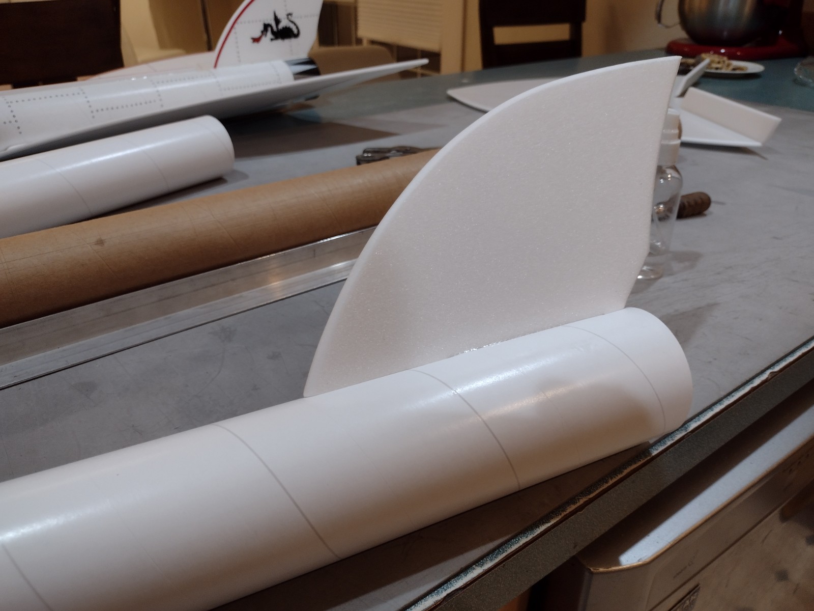
- Glue the vertical stab in place
-
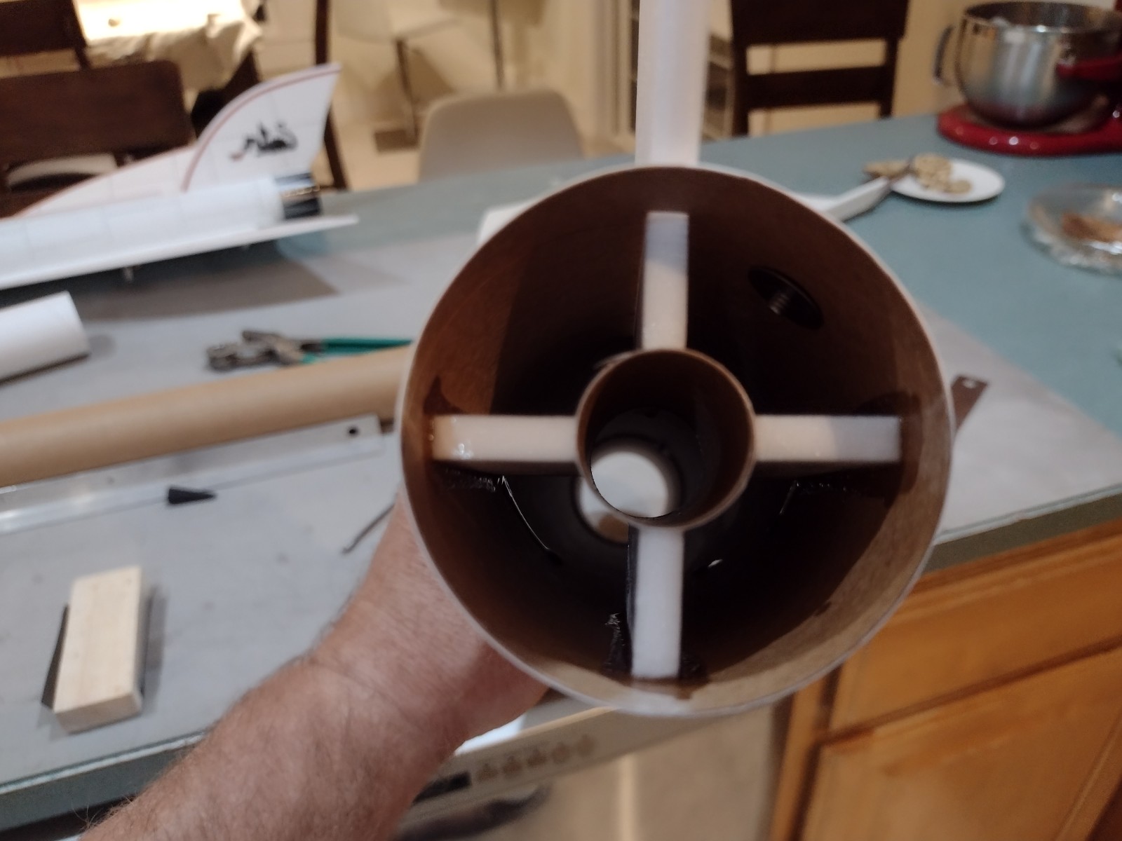
- Fit, sand and install the motor mount inset about 3/4″
-
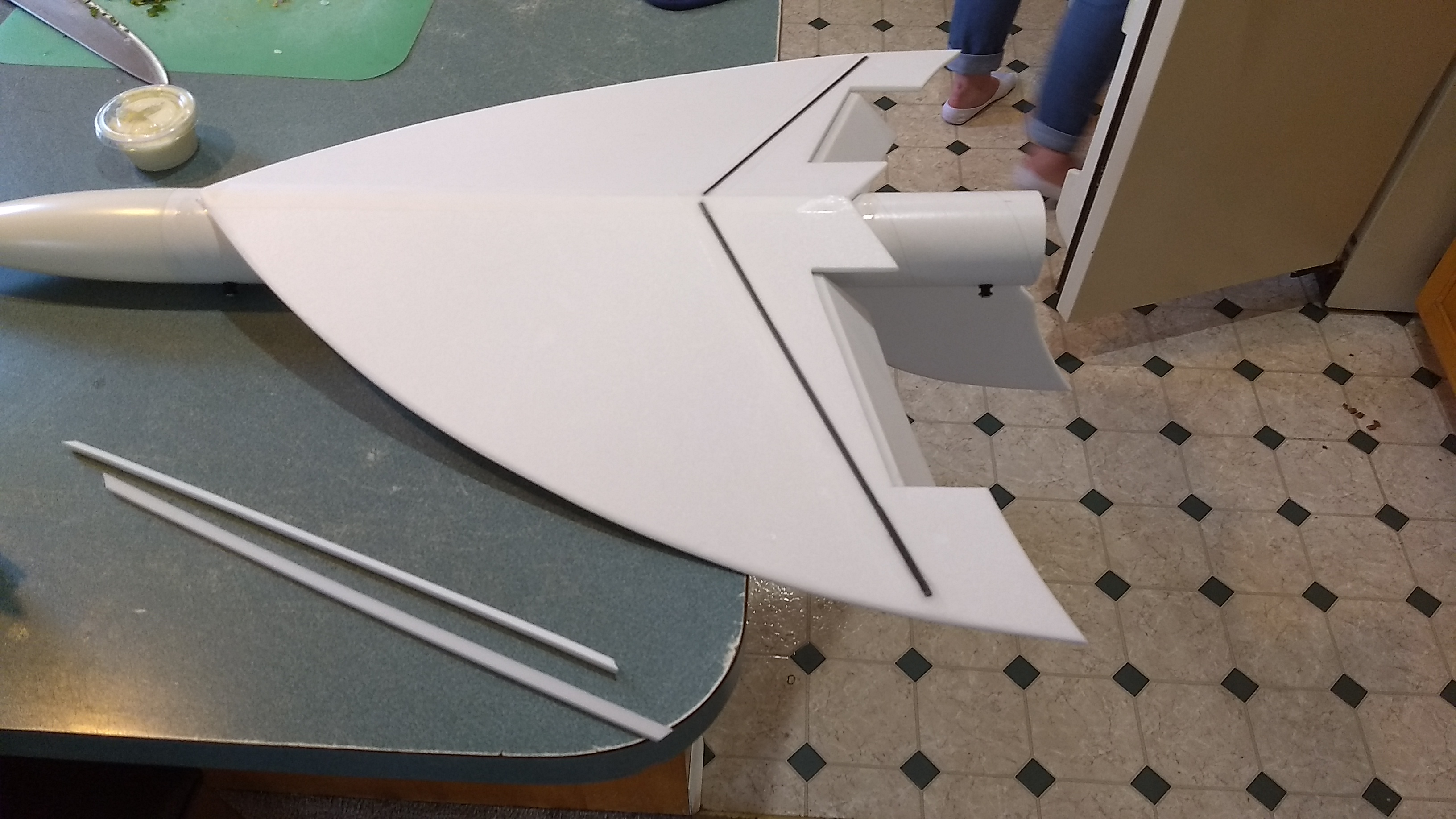
- Glue the wing on the body tube keeping the front and rear marks aligned with the wing.
-
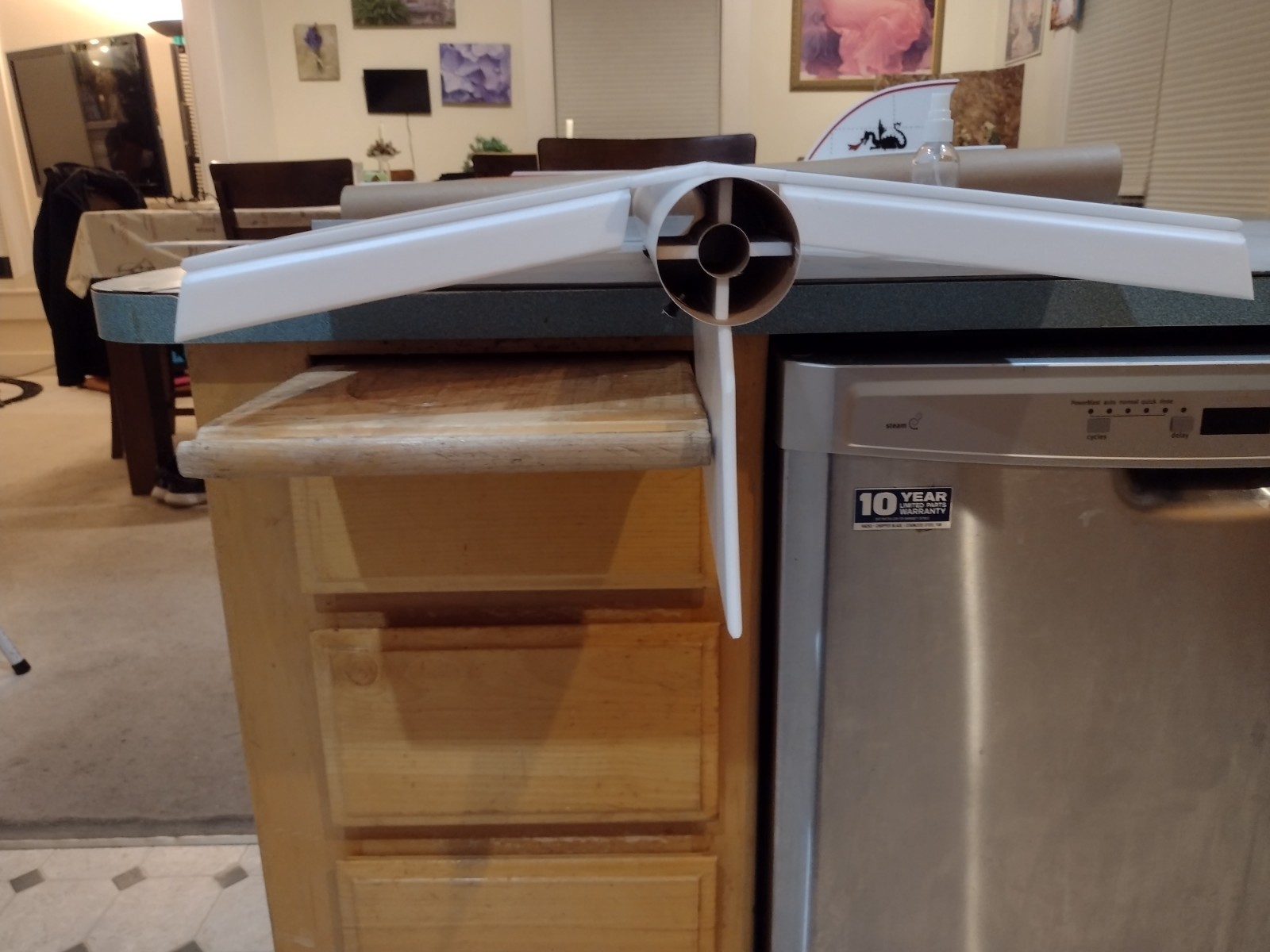
- Keep the vertical stab vertical and the wing tips about the same distance off the table top on each side.
-
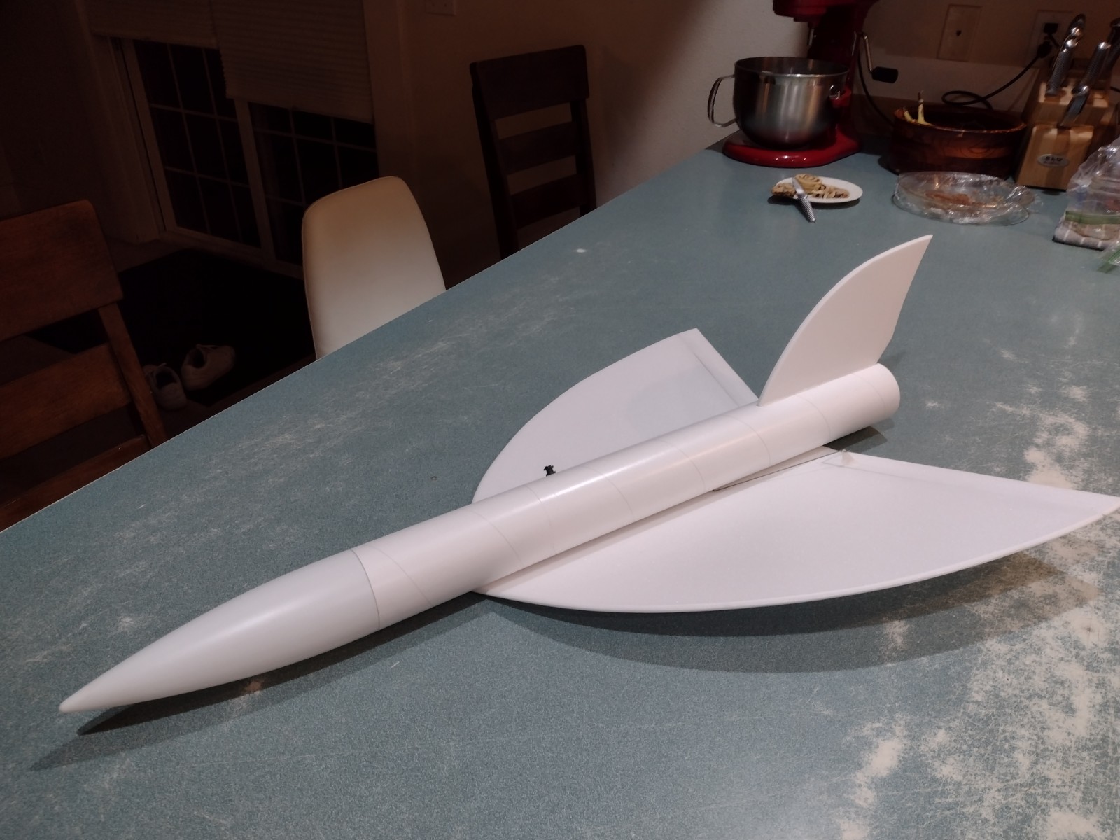
- Completed airframe ready for radio install.
-
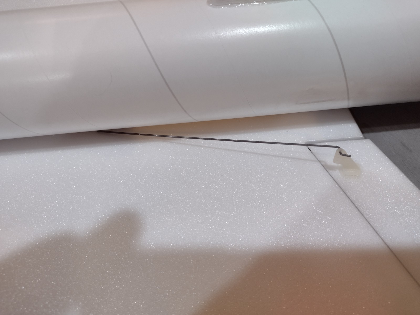
- Glue the pushrod horns into each control surface top, then apply glue to the prongs on the bottom to lock them in place.
-
- Attach a servo to each pushrod and mark where the servo pocket will be cut.
-
- Cut a servo pocket on each side.
-
- Glue the servo in place keeping the control surface level.
-
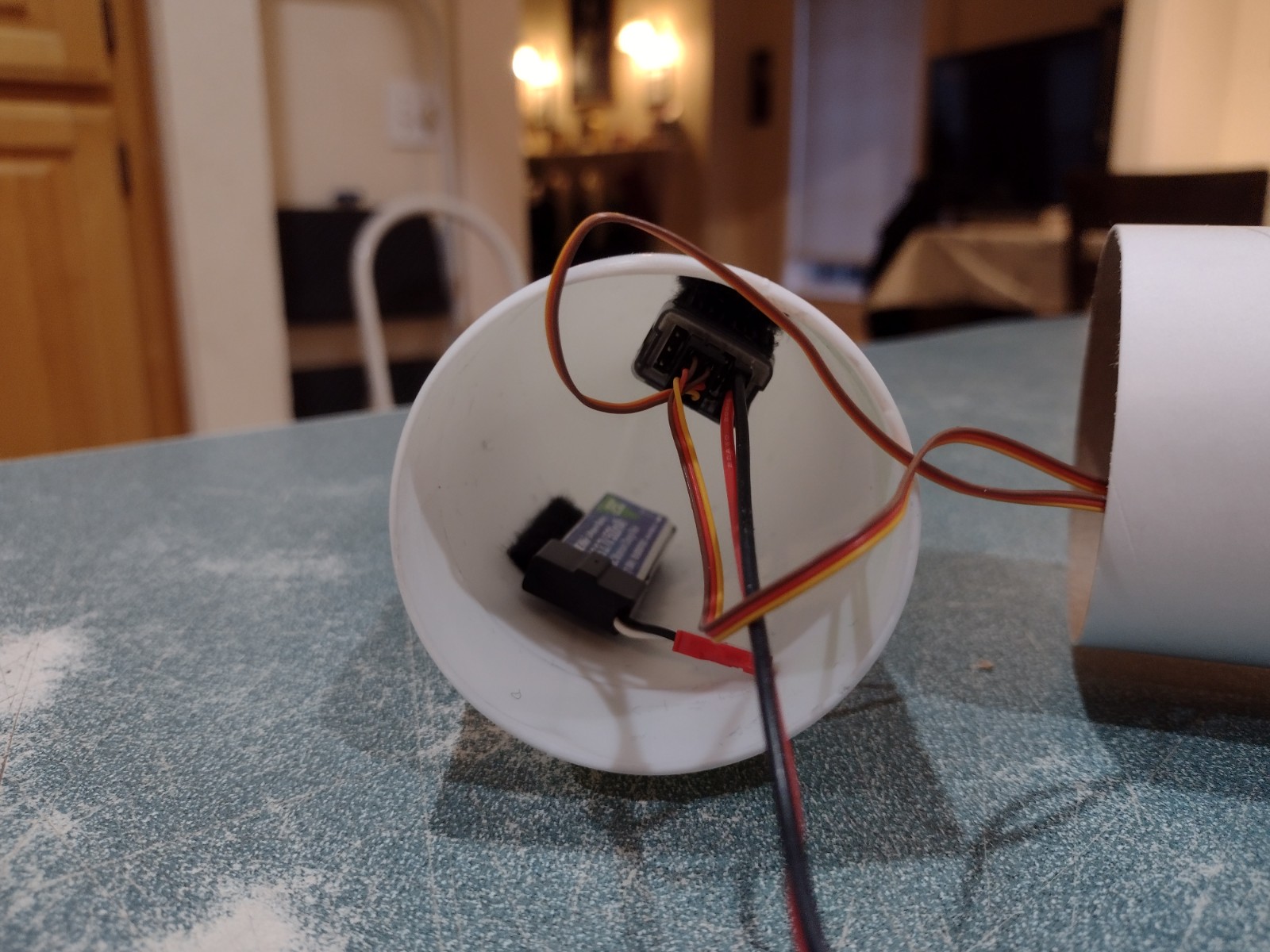
- Attach the receiver and battery inside the nose cone with included velcro
-
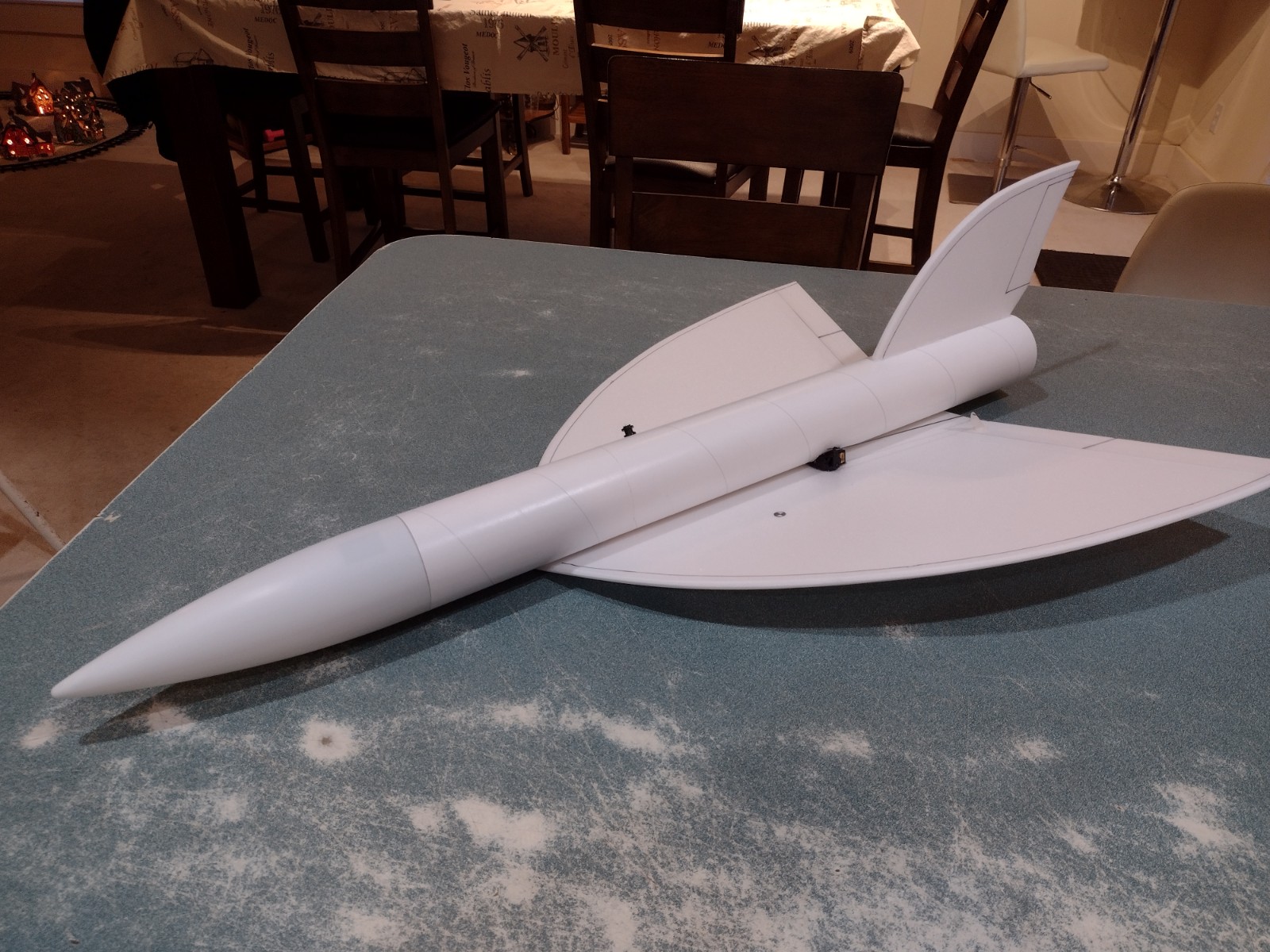
- Completed model ready for paint and decals.
-
- Balancing the model with battery and loaded motor installed after painting and trim applied.
-
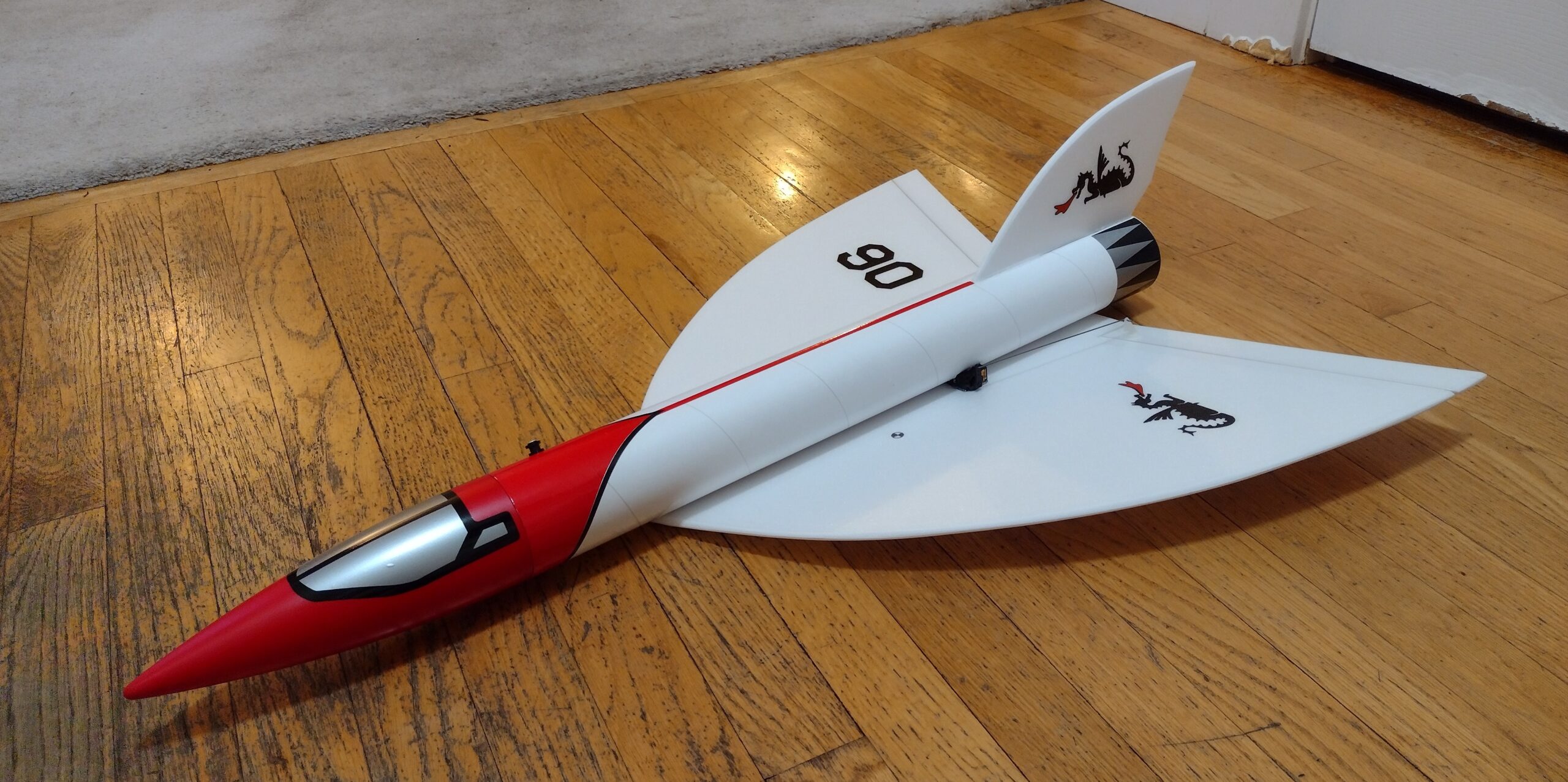
- Completed Model with stickershock decals
-
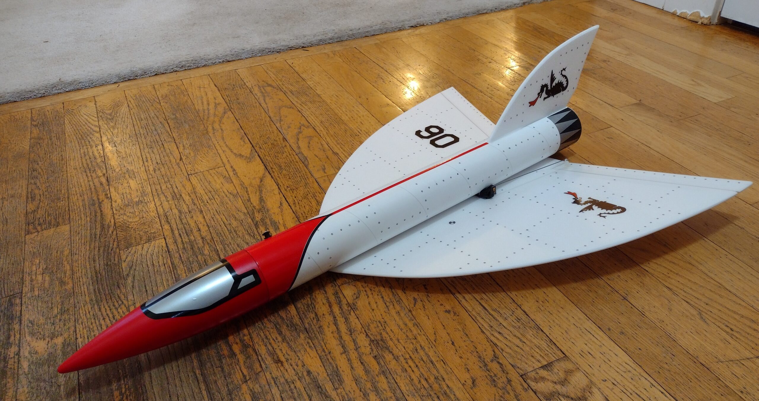
- Added rivet detail using sharpie pen and styrene template
-
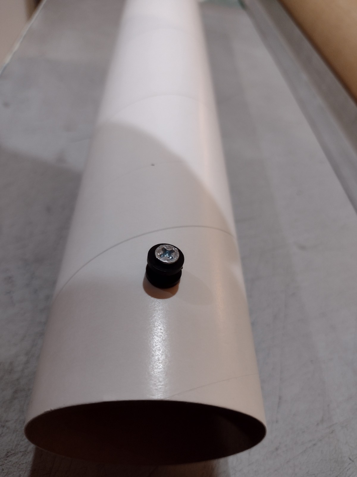
- Install the front and rear rail buttons, if using the vinyl decals install these after applying the decals as you will have to trim the vinyl covering the holes to install them.
-
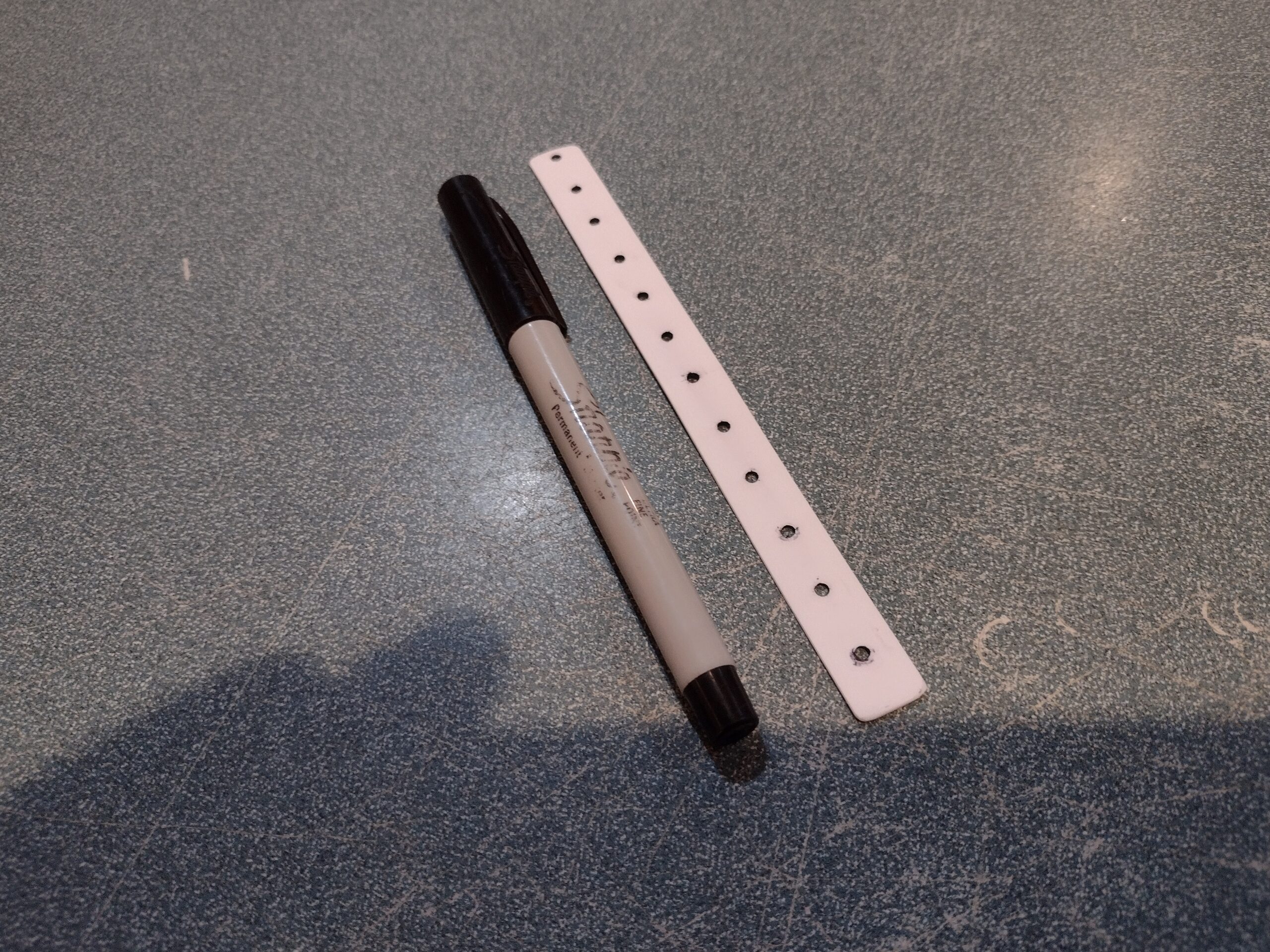
- simple styrene strip with holes punched every 1/2″ and a sharpie pen
-
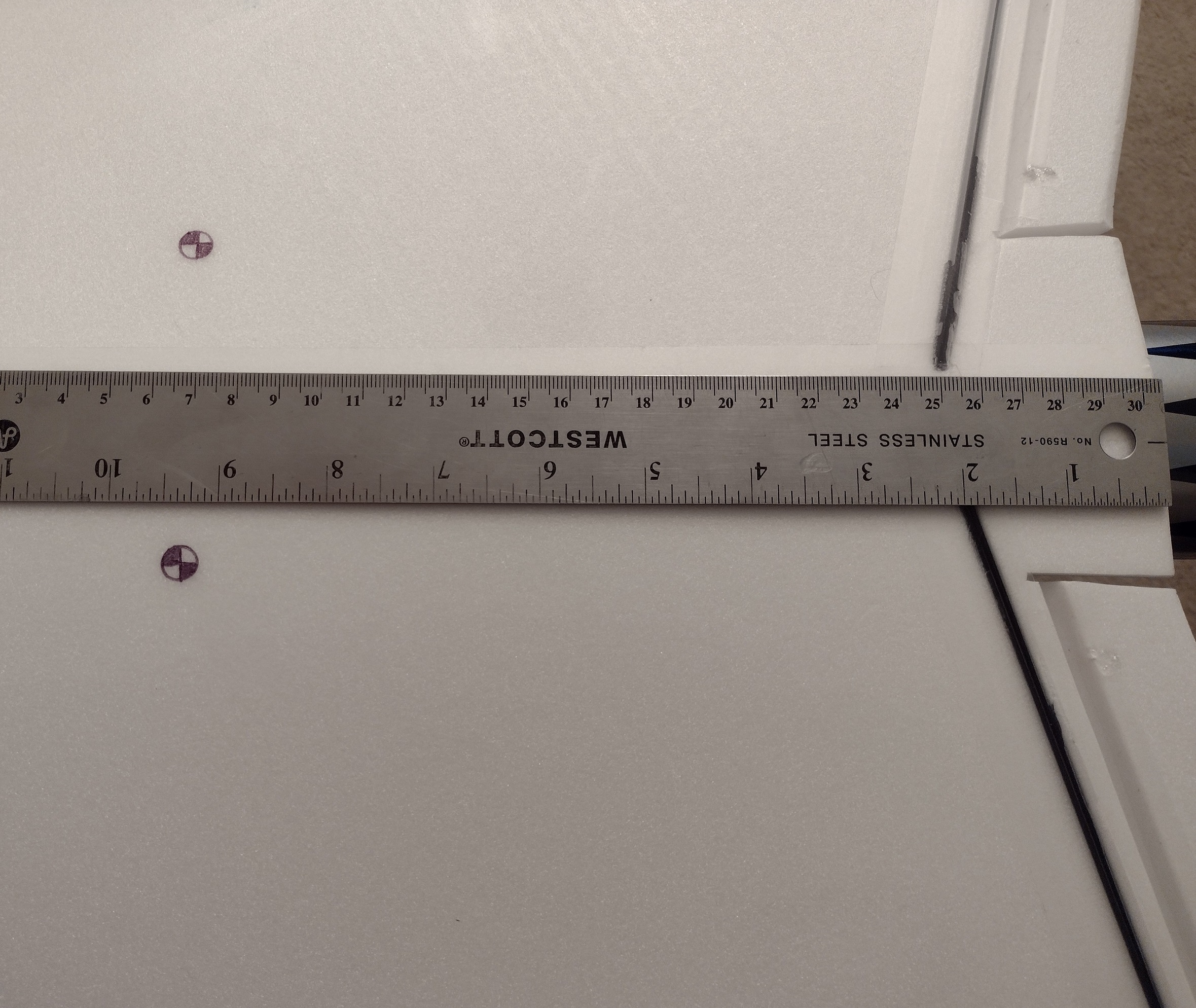
- CG as described in the instructions
-
- Optional Stickershock decals
-
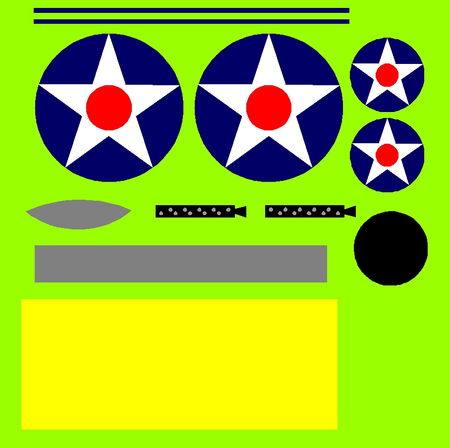
- Alternate “Peashooter” allied style decals
-
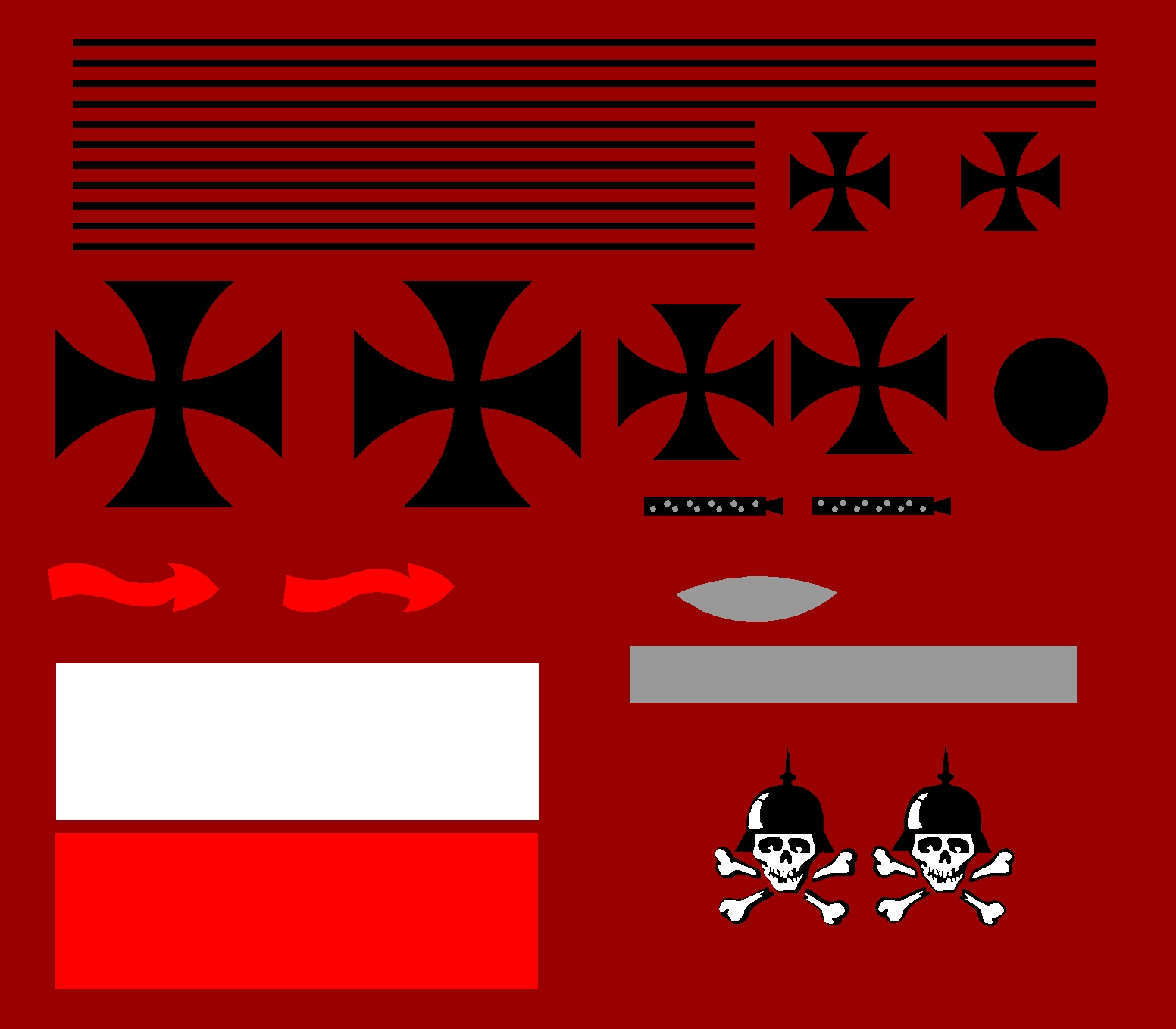
- Alternate German Decals
-
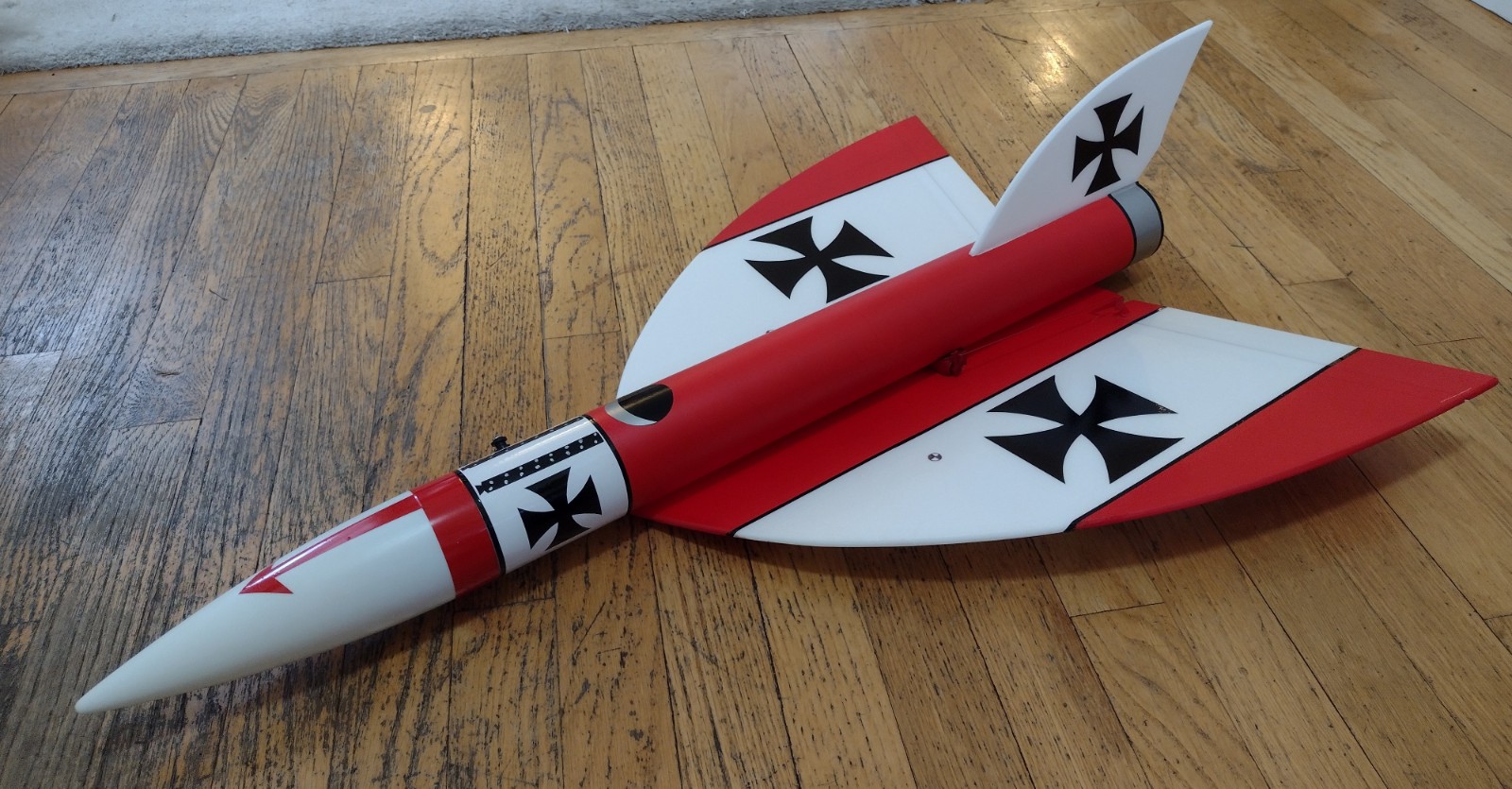
- Red German style
-
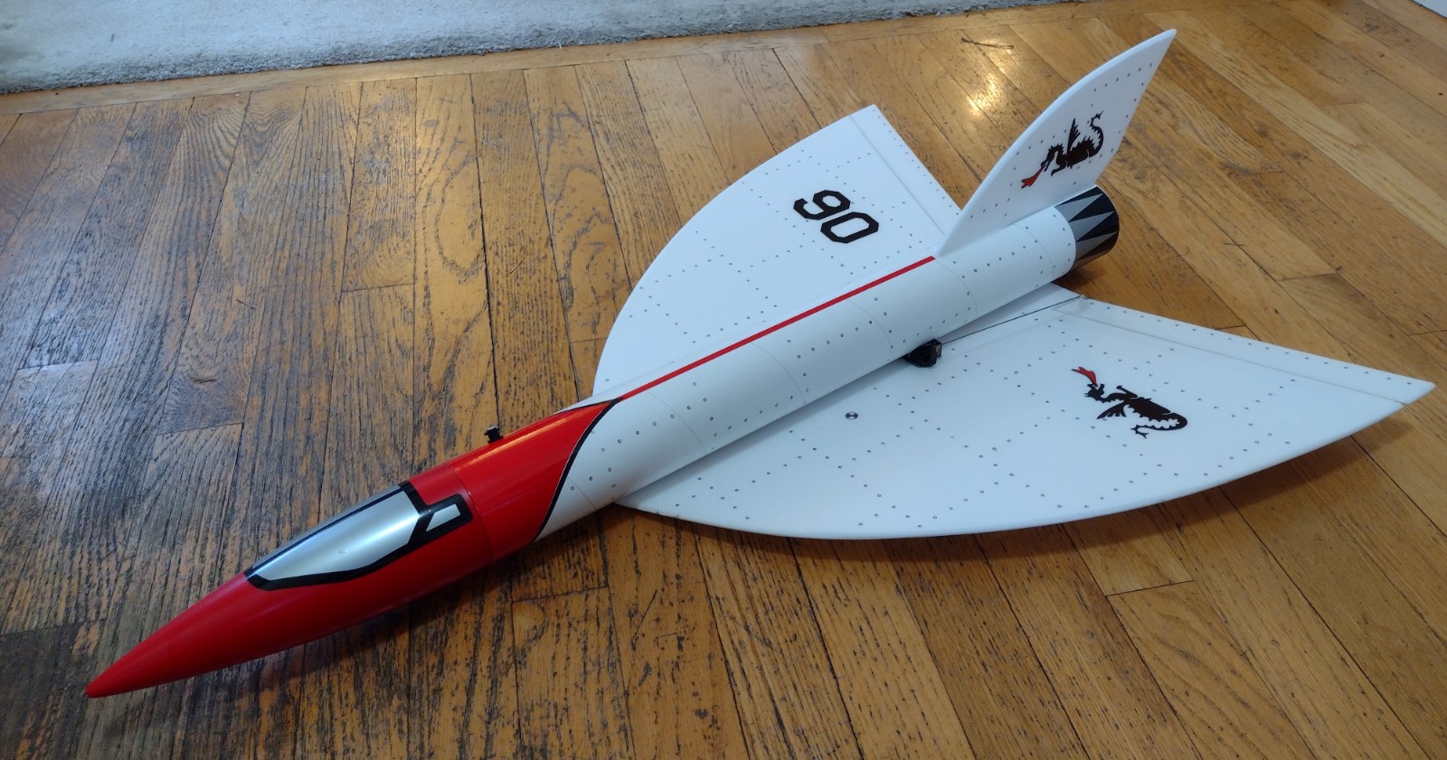
- Dragonship Style
-
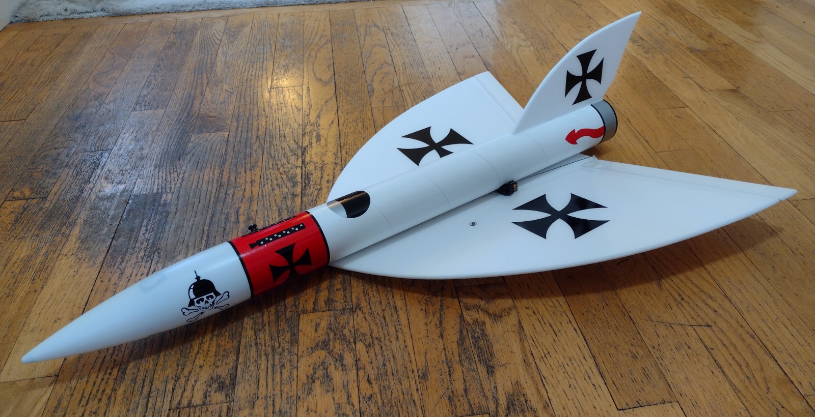
- White German Style
-
- Group Photo