
Radio Controlled Rocket Glider Kits
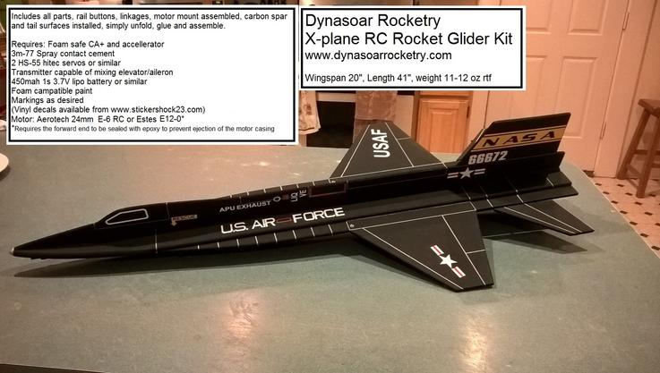
X-Plane Rocket Glider Kit
The X-Plane is styled after a real hypersonic research vehicle. The model features a full flying tail for pitch/roll control just like the real plane. Construction is straight forward and gives a great looking model with very good boost/glide characteristics.
Please refer to the notes on items needed for completion and flying, then read the instructions completely before starting assembly. The assembly photos are for general reference but may not include every step in the manual. You can refer to the video here to see how to assemble the X-Plane on the main Instruction page as well.
CG location for rocket flight 1/4" rearward from the wing/fuselage intersection
(for electric flight start 1/4" forward of the rocket CG)
Welcome to the world of rocket boosted radio control gliders. This is not a model for a novice RC pilot, but anyone who is comfortable with RC flying of a medium speed model should be fine. This model has a very moderate glide and slow landing speed. Read through the instructions, look at the photos and be sure you understand the step before commiting to cutting or glue.
X-Plane Rocket glider instructions
Identify all pieces, the kit should contain:
Wing and rear fuse(taped together)(A)
2 pushrods
Forward FuselageTop view (B)
Fuse doubler(taped together)(E)
Upper fuselage side view(taped together)(C)
Lower fuselage side view(taped together)(D)
Motor mount
Velcro(for battery and rx/bec attachment)
2 Rail buttons(2 collars, 2 screws, 2 washers, 2 plastic plugs) or 1 Launch lug and styrene strip for mounting
Styrene strips for reinforcing the bottom of the model and the rail button/launch lug attachment.
3M blenderm tape
Lead weight
Spare depron
Optional(if ordered):
Electric motor adapter
Notes before starting:
Reference to CA+ means foam safe CA+, normal CA+ will melt the foam!
You may use 320 grit sandpaper and a sanding block to slightly round the edges of the foam if you prefer that look. It will not markedly impact the flight performance either way. Be very careful and use a light touch, it is very easy to catch the foam on the edge of the paper and tear the foam.
Epoxy is not needed in this model. Weight is critical and the model is designed for the thrust and flight loads. Weight in the rear end is bad and will require additional weight in the front of the model.
Assembly:
- Unfold the front and rear wing halves, place upside down on a table and glue the joint together using CA+ and accellerator(leave the tape in place).
- Flip the wing over, let the rear with control surfaces overlap the edge of the table so it lays flat. Tape the forward fuselage top view in place against the wing, make sure it is straight, use 3m blenderm tape. Flip the model back over and then glue the joint together using CA+ and accelerator.
- Flip the wing over again with the rear overlapping the end of the table.
- Unfold the fuselage top view doubler and glue the joint at the tape seam with CA+ and accelerator.
- Using lightly sticky masking tape, Mask off outside of the black lines for the fuselage doubler Mask off the top of the wings, and the control surfaces with plastic so you do not get any spray adhesive on them. If you do, you can use CA accellerator to remove the glue.
- Use 3m77 spray adhesive to spray an even layer of adhesive on the bottom of the fuse doubler and the top of the wing in the center that was left unmasked.
- Remove the masking tape and let the adhesive set for 30 seconds to a minute.
- Carefully lay the fuse doubler on the top of the wing keeping the motor mount cutout aligned and the tip of the doubler aligned with the centerline of the fuselage.
- Carefully insert a pushrod into each control horn. The pushrod goes in from the inboard end. Note** if your control horn is black use the third hole from the far end of the control horn, if it is white use the furthest hole out. You must do this now because it is hard to do once the fuselage side views are in place. Please handle the model carefully and do not snag the control horns on anything, you may want to tape them down to the control surface for now. You may need to twist the wire back and forth to get it to go into the hole, it should be snug and slop free. It may be necessary to rotate the pushrod end to drill the hole large enough to fit, be careful not to puncture your finger. Be careful to support the control horn so that you do not break the glue joint in the control surface. It is snug but it will fit with patience.
- Unfold the top fuselage side view and glue the the seam where it is taped using CA+ and accelerator. Make sure it is straight. Test fit assembly in the top of the fuselage, be careful to not break off the tabs, the tabs should align the fuse side view straight, The foam compresses slightly so it is ok to press them in place. Once aligned perpendicular to the wing and ensuring it is straight with a straight edge, apply a bead of CA+ to both sides of the joint.
- Flip the model over, lay it so that half the model is laying on the edge of a table so it is suported flat and put a weight on the wing half to keep it from falling off.
- Unfold and glue the front and rear lower side view fuse pieces together, at the tape joint. Use CA+ and accelerator, make sure it is straight. Test fit the assembled lower fuselage side view piece into the notches in the wing and fuse. Make it fits well. Make sure the rear motor mount notch is aligned with the top view motor mount notch. Once happy with the fit and making sure it is straight down the middle of the wing, apply a bead of CA+ on both sides and use accelerator to set the glue. Make sure the fuselage does not get any twist or warp.
- Test fit the motor mount into the rear of the model. It is useful if you have a motor casing in the tube to hold it round. Make sure it fits, Make sure the fuselage pieces are aligned straight and the motor tube is aligned with the centerlines of the model. Make sure the motor hook is not blocked by the foam and can be reached to release the motor. I put the motor hook at the lower right quadrant when looking at the rear of the model, at about the 4:30 position, so it is not visible. Make sure the ventral and vertical stabilizers are straight down the model without any warp, when happy, use CA+ and make a bead on each joint and set it with accellerator. Make sure the motor tube is attached well but don’t overdo it and don’t use epoxy, tail weight is a killer and there isn’t much force on the motor tube during launch. The foam is plenty strong enough to support the forward thrust and no thrust ring is needed. I’ve flown many flights and the forward foam has never melted or failed.
- Glue a styrene strip on the bottom of the nose area where it will make landing contact. Also glue a styrene strip to the front and bottom of the ventral stab. This helps prevent road rash when the model lands.
- Install the launch lug or rail buttons, read and understand before doing this step:
- Use the included plastic plugs to mount the rail buttons. Make two starter holes with a screwdriver or similar round tool that is slightly undersized. These are located into the bottom side view of the fuselage about 1/2" up from the bottom, 6" forward of the wing LE and 6" to the rear of the wing LE. Put a bit of CA+ underneath the plastic head and push each plug all the way into the fuse. Trim the piece of plastic plug that is sticking out the other side flush with the fuse. Use a screw, a plastic collar and a plastic washer to complete the rail button guide. You'll need to keep the collar centered when assembling as the screw is slightly undersized for the hole in the collar.
- If you have an older kit with one piece rail buttons, follow these instructions If you are using rail buttons, glue one of the short styrene strips lengthwise about 1/8” up from the bottom of the lower fuselage side view 6” forward of the leading edge of the wing, and 6” the rear of the leading edge of the wing. Glue one on the other side opposite to the first set. This will reinforce both sides of the foam where the rail button will attach. Drill a small hole through the center of the styrene to fit the screw and then screw in the two rail buttons. At this loacation, the rail should not interfere with the servos or battery/rx but do a test fit on a rail to be sure.
- If you have an older kit with one piece rail buttons, follow these instructions If you are using rail buttons, glue one of the short styrene strips lengthwise about 1/8” up from the bottom of the lower fuselage side view 6” forward of the leading edge of the wing, and 6” the rear of the leading edge of the wing. Glue one on the other side opposite to the first set. This will reinforce both sides of the foam where the rail button will attach. Drill a small hole through the center of the styrene to fit the screw and then screw in the two rail buttons. At this loacation, the rail should not interfere with the servos or battery/rx but do a test fit on a rail to be sure.
- If using a launch lug, glue the wide styrene strip to the launch lug with CA+, then glue the assembly to the side of the lower fuselage side view centered on the leading edge of the wing using CA+.
The basic construction is now complete.
Radio Installation
Note: Your radio needs to be configured for Delta mixing, this means that the servo arms will move the same direction during elevator stick movement and opposite for aileron stick movement. Connect your servos to the receiver one in the aileron connection and one on the elevator connection and apply power. Use a servo arm at least 9/16” long and with holes small enough that there won’t be slop with the pushrod wire when installed. I use the hole furthest out on the servo arm, to maximize movement. On some servos there are a long two-ended servo arm, you can trim off one end if needed to get sufficient length. Zero out any trim settings on the transmitter. The model once the motor has burned out is nose heavy and flying wings lose pitch authority when nose heavy so you want as much up elevator travel for trim/flare as possible.
- Install the other end of the pushrod to the servo output arm, again making sure the servo wire is toward the fuselage side of the model. If the wire is too tight, you can use twist an exacto knife in the servo arm hole to make it larger, but be careful and do not make it too large. Once connected, tape each servo in place so that the control surfaces are centered. Make sure the pushrod won’t catch on the leading edge of the control surface. Flip the model right side up and look at it from the rear. Moving the transmitter stick back(up elevator) should move both stabilizors TE’s up. Moving the transmitter stick to the right should move the right TE of the stabilizer up and the left one down. If you can’t get the servo reversing to give you the right polarity try swapping aileron/elevator inputs to the receiver or turning the servos over and swapping the servo arms to the other side of the output shaft. If that is correct, continue.
- Flip the model upside down and supported. The servos may be attached to the model using double back servo mounting tape(not included) or by directly gluing the servo to the wing with CA+ or a small amount of epoxy. Double back servo tape can loosen over time and with exposure to heat, I prefer to glue the servo in place. With the radio still on, put a small amount of glue on the servo, being careful not to get any near the output shaft. And set it in place on the model keeping the control surface centered. Do the same to the other side. Make sure the glue is set before continuing. Again, make sure the pushrod is aligned straight and will not catch on the LE of the control surface.
- Flip the model back right side up. Make sure the control surfaces are centered, use trims if needed. Now measure the control surface movement. Full elevator movement should be 1” in each direction. Aileron movement should be about about ¾”. With modern radios you can typically set these movements. Since the model will be nose heavy, extra stabilizer movement helps to give sufficient authority during glide. Roll rate is not extremely fast during glide so you need plenty of movement. Set up dual rates with lower movements if you are worried but boost with higher settings till you are comfortable.
- If you have a flap/elevator mix you can program up elevator to a switch setting. The model needs approximately ¼ to 3/8” of up stabilizer during glide. Boost will use completely neutral settings for the first flight. If you can’t set the up elevator to a switch on your radio you’ll have to manually put in glide trim which is hard to do while flying the model.
- Once complete you can tape the servo wires to the wing using the blenderm tape. Use the included Velcro to attach the receiver to the model. Mount the receiver as far forward as it can go. This allows you to be able to remove and replace the receiver if needed for repairs or for painting.
- Use some Velcro to attach battery near the receiver.
- Insert a loaded rocket motor into the motor mount. Use the heaviest motor you plan on flying.
- Support the model at the balance point indicated for boost. I use two pencils with the eraser pointed up and held in place with a small hand vice. Place the model upside down on the pencil erasers with the erasers just behind where the leading edge of the wing intersects the top view of the fuse as indicated in the plans so that the model balances slightly nose down. You can place stick on lead weights near the nose of the model to balance it. If you are having trouble balancing, you can use servo extension wires to move the receiver and battery further forward, use a heavier battery or add more nose weight.
- Do not try to fly the model with it balancing it behind this point. The adage is, a nose heavy model flies poorly, a tail heavy model flies once.
- To paint the model you can remove the receiver/bec and mask off the servos and Velcro strips on the model. Alternatively you can tape down the bec wires and just mask over the bec and receiver and servos and battery velcro and paint over them to hide the tape and wires…don’t get any paint directly on the connectors or electronics boards. Make sure no paint will get on the servo output arm. Make sure to test the paint on a scrap piece first to ensure it won’t melt the foam. I use Model Master(testors) or testors small rattle cans for painting directly on the foam. Model master flat black is perfect.
- Use a silver sharpie to add panel lines if desired.
- If your self adhesive vinyl/mylar decals or lettering I spray the back of the decal with 3m-77 spray, then place it on the model while the spray is still wet and they will hold better.
- Re-install the receiver and battery.
Copyright © dynasoarrocketry.com. All rights reserved.
