
Radio Controlled Rocket Glider Kits
SST Rocket Glider Kit
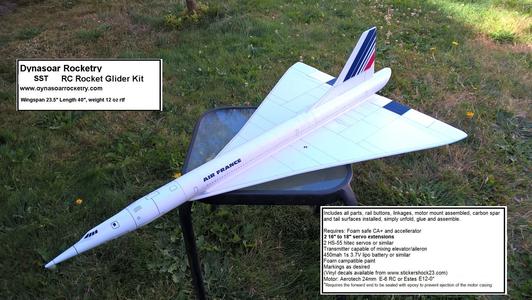
The SST RC Rocket glider kit is modeled after the supersonic Concorde Mach2+ airliner. It has a light wing loading giving it a very nice glide and easy/stable boost. It comes with a plastic nose cone, 2" white tubing for the body and depron wing and tail surfaces. Construction is very simple and takes about an hour. You will need two 10 gram type servos, two 16”-18" servo extensions, a receiver, and a small 500mah single cell lipo battery. You will need a transmitter with delta or elevon mixing.
Please refer to the notes on items needed for completion and flying, then read the instructions completely before starting assembly. The assembly photos are for general reference but may not include every step in the instructions. If you want hardcopy to work from, all you have to do is click/drag/select and copy all of the text below the photos, open word and paste with "keep original format" and it looks exactly like it does online then you can print it.
CG location for rocket flight: 13 5/16” forward of the wing trailing edge.
Welcome to the world of rocket boosted radio control gliders. This is not a model for a novice RC pilot, but anyone who is comfortable with RC flying of a medium speed model should be fine. Read through the instructions, look at the photos and be sure you understand the step before committing to cutting or glue.
SST Rocket glider instructions
Identify all pieces, the kit should contain:
1 wing taped together
2 wing spars(carbon fiber)
2 pushrods
1 vertical stabilizer
2 long Foam wing reinforcing strips
2 short foam motor reinforcing strips
1 forward body tube
1 rear body tube with angled cut, slot and coupler installed
Six square foam blocks.
Motor mount
Velcro(for battery and rx/bec attachment)
2 Rail buttons plastic mounting plugs/screws or 1 Launch lug
3 landing skids
3M blenderm tape
Lead weight
Spare depron
Notes before starting:
Reference to CA+ means foam safe CA+, normal CA+ will melt the foam! Normally you need to use accelerator to get the CA to set on the foam since there is nothing for it to soak into and activate.
You may use 220-320 grit sandpaper and a sanding block to slightly round the edges of the foam if you prefer that look. It will not markedly impact the flight performance either way. Be very careful and use a light touch, it is very easy to catch the foam on the edge of the paper and tear the foam. Do any sanding before assembly.
Epoxy is not recommended for this model except for the motor mount. Weight is critical and the model is designed for the thrust and flight loads. Weight in the rear end is bad and will require additional weight in the front of the model. The epoxy is recommended only for the motor mount to give time to get it aligned properly before the glue sets. Use it sparingly only on the motor mount!
Assembly:
- Unfold the wing and glue the front and rear tape joints using CA+ and accelerator, make sure it is flat
- Glue the two wing spars in the pre-slotted areas on the bottom of the wing with CA+ and then tape over with the included blenderm tape.
- The rear body tube with the angled cut already has the coupler glued in place. Glue the front body tube that does not have the angled cut into the coupler, you don't need a lot of glue as the wing will support the joint. Make sure you align the wing line on the bottom of the two tubes when you glue it in place, this is used for making sure the wing is straight.
- Note the motor tube has tape and a motor hook on it and a line marked. Do not glue to the taped side, glue to the side with the line. Note also the motor hook has one end that is glued and one that is free to move. The free moving end is the rear of the motor mount. Using a VERY small amount of epoxy glue the motor tube into the rear of the body tube. The motor tube should be flush with the rear body tube cutout at the bottom. Use the line on the motor mount and the line inside the body tube to help get it straight. Look from the rear and the front of the body tube to make sure the motor tube is aligned straight, take your time and make sure it is right. The motor hook should be visible through the slot in the top of the tube.
Glue one of the short reinforcing foam strips on each side of the motor mount. Use CA+ and put a small fillet as best you can on both the body tube and motor tube. These help give extra support to the motor tube - Lay the wing so that the two control horns are facing down and over the edge of a table so that the wing can lay perfectly flat. Using the wing alignment line on the wing and body tube use CA+ to glue the body tube assembly to the wing. Make sure the rear of the tube is flush with the rear end of the wing. Make sure the tube is not rolled to one side or the other and that the vertical tail slot is facing up. The front of the body tube will extend slightly past the front of the wing.
- Apply CA+ foam safe glue to one of the long reinforcing strips and glue one on each side of the wing/body tube joint. The reinforcing strip should align with the rear of the model but won't go all the way to the front of the wing. This piece is there to give more gluing surface to the wing/body tube. If you push in too hard on these strips it can cause the body tube to rotate slightly, so pay attention. Once they are in place put a fillet of CA+ on both the wing and body tube joints.
- Use CA+ to Glue the vertical stab to the body tube using the pre-cut slot. Make sure it is perpendicular to the wing. Sometimes the foam can have a slight curve to it, use a straight edge to make sure the root of the vertical stab stays straight while the glue sets. Put a small fillet of CA+ on each side.
- If using rail buttons, remove the screw and rail buttons from the plastic plugs. Using a round tool or drill bit make a slightly undersized hole in the bottom of the wing and through the body tube at the two X marks. Using CA+ glue the two plugs into the holes, make sure the seat fully. Place the rail button washer and collar onto the screw and then screw it into each plastic plug. You’ll need to manually center the collar as you tighten to make sure it is centered.
- At the bottom/front of the wing is a small line marked skid. Using a tool, make two starter holes through the wing and into the body tube to mount one of the landing skids. Make sure the skid is lined up with the rail button and does not drag on the rail button slot. This will help prevent the nose from dragging on the ground when landing on a rough or hard surface. Glue it flush with the wing using CA+
- If you are using a launch lug I suggest gluing it to the wing/body tube joint so that it is not on the bottom to catch on anything when landing. Mount the lug approx. in the middle of the model.
- Insert the two pushrods into the outermost hole in the control horns on the elevons. The rods go in from the inboard side of each control horn. You will need to twist the pushrod to get it to go into the hole, be careful and don't poke your finger, go slowly so that it fits snugly
The basic construction is now complete.
Radio Installation
Note: Your radio needs to be configured for Delta mixing, this means that the servo arms will move the same direction during elevator stick movement and opposite for aileron stick movement. Connect your servos to the receiver one in the aileron connection and one on the elevator connection and apply power. Use a servo arm at least 9/16” long and with holes small enough that there won’t be slop with the pushrod wire when installed. I use the hole furthest out on the servo arm, to maximize movement. On some servos there are a long two-ended servo arm, you can trim off one end if needed to get sufficient length. Zero out any trim settings on the transmitter. The model once the motor has burned out is nose heavy and flying wings lose pitch authority when nose heavy so you want as much up elevator travel for trim/flare as possible.
- Connect a servo to each pushrod, the servo wire should be closest to the center and the output shaft is outboard toward the wing tip. If the wire is too tight, you can twist an exacto knife in the servo arm hole to make it larger, but be careful and do not make it too large. Once connected, tape each servo in place so that the control surfaces are centered. Flip the model right side up and look at it from the rear. Moving the transmitter stick back(up elevator) should move both elevons up. Moving the transmitter stick to the right should move the right elevon up and the left elevon down. If you can’t get the servo reversing to give you the right polarity try swapping aileron/elevator inputs to the receiver or turning the servos over and swapping the servo arms to the other side of the output shaft. If that is correct, continue.
- Flip the model upside down and supported. The servos may be attached to the model using double back servo mounting tape(not included) or by directly gluing the servo to the wing with CA+ or a small amount of epoxy. Double back servo tape can loosen over time and with exposure to heat, I prefer to glue the servo in place. With the radio still on, put a small amount of glue on the servo, being careful not to get any near the output shaft. And set it in place on the model keeping the control surface centered. Do the same to the other side. Make sure the glue is set before continuing. The servo and pushrod should be at 90 degrees to the hinge line so that it moves easily and fully. The servos should be far enough away from the center of the wing so that the rail will not drag on them.
- Flip the model back right side up. Make sure the control surfaces are centered, use trims if needed. Now measure the control surface movement. Full elevator movement should be 3/4" to 1” in each direction, aileron movement should be 1/2" in either direction. Since the model will be nose heavy, extra elevon movement helps to give sufficient authority during glide.
- If you have a flap/elevator mix you can program up elevator to a switch setting. The model needs approximately 1/4” of up elevon during glide and slightly less than1/8" of down trim for boost. If you can’t set the up elevator trim to a switch on your radio you’ll have to manually put in boost and glide trim in flight which is hard to do while flying the model.
- Attach a 16-18" servo extension to each servo. You just need to be able to route the wire to the front of the tube to attach it to the receiver.
- Make a 1/8" by 1/2" slot in the bottom of the wing near the center through the body tube and pass the wires through to the inside and toward the front. Make sure your slots are located so that the wires will not drag on the rail. Once the wires are routed, use the blenderm tape to cover the wire and slot. You can cut a slot with an exacto knife to recess the wires into the foam so that there is no dragging on the rail.
- Attach the servo wires to the receiver and make sure they are going the right direction.
- Use the included Velcro to attach the receiver at the inside top of the body tube ffar enough in so that tit will clear the shoulder of the nose cone. This allows you to be able to remove and replace the receiver if needed for repairs or for removing the servo wires. I attached the battery inside the nose cone on the shoulder using Velcro as well. My battery wire adapter is long enough to reach from the receiver to the battery.
- Glue three of the foam blocks together into a stack. Glue the other three to make a second stack. These will be glued to the bottom of the wing just in front of each servo to protect the servo arms from landing damage. Glue one block in front of each servo, make sure that it does not get in the way of the servo arm movement. Mount a landing skid into each block, use a tool to make starter holes and then CA+ the skid into the block. The skid should stick down further than the servo arm and protect it from landing damage.
- Insert your heaviest loaded rocket motor into the motor mount
- Support the model at the balance point indicated. I use two pencils with the eraser pointed up and held in place with a small hand vice. Place the model upside down on the pencil erasers on the balance point indicated in the instruction page. Use the included lead weights to balance it. Do not try to fly the model with it balancing it behind this point. The adage is, a nose heavy model flies poorly, a tail heavy model flies once. Cut the lead weights into smaller pieces and push them as far forward into the nose cone as possible to minimize how much weight you add. I needed approx. ½ ounce. Use a few drops of CA+ to secure them from moving. You can also securely tape the weights to the outside of the model for the first few trim flights if you wish, then glue them inside once you are happy with the balance point.
- If you paint the model, make sure you test it on scrap foam first.
- If you are going to paint the model, you can mask off the servos. Make sure no paint will get on the servo output arm. Make sure to test the paint on a scrap piece first to ensure it won’t melt the foam. I use Model Master(testors) or testors small rattle cans for painting directly on the foam.
- I used vinyl markings from stickershock 23 for the trim colors on my model. With the vinyl from stickershock23 it helps once applied to use a hair dryer on hot to soften the material and then push it down onto the model with a towel. It helps it conform and stick much better, especially on painted surfaces.
- Use a black sharpie to add panel lines if desired, I ran a fine line sharpie into some of the panel lines in the nose cone and it really sets it off. I did not mark the panel lines on the cockpit but instead filled those with plastic filler and sanded them flush and then used small trim vinyl pieces to make multiple little cockpit windows so they would look more to scale with the actual Concorde. I made a little template out of cardboard with holes for windows spaced about ¼” apart and about 3” long and used a sharpie pen to make the windows and doors on my model. Stickershock can do them for you in vinyl and make it much easier.
- Re-install the receiver and battery
- Flying: See the Instruction/Information link at the top for flying instructions Note, my prototype needed 1/8" for downtrim for boost and 1/4" uptrim for glide. Be ready on the first few flights to keep the model straight till you have the trims set perfectly for boost and glide.
Copyright © dynasoarrocketry.com. All rights reserved.
