
Radio Controlled Rocket Glider Kits
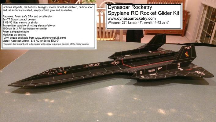
Spyplane Rocket Glider Kit
The Spyplane is styled after a real mach3+ reconnaisance aircraft. Construction is straight forward and gives a good looking representation but with very easy boost and slow glide recovery.
Please refer to the notes on items needed for completion and flying, then read the instructions completely before starting assembly. The assembly photos are for general reference but may not include every step in the manual.
CG location for rocket flight 3/16" forward of the notch where the wing meets the ramjet
(for electric flight start 1/4" forward of the rocket CG)
Welcome to the world of rocket boosted radio control gliders. This is not a model for a novice RC pilot, but anyone who is comfortable with RC flying of a medium speed model should be fine. This model has a very moderate glide and slow landing speed. Read through the instructions, look at the photos and be sure you understand the step before commiting to cutting or glue.
Spyplane Rocket glider instructions
Identify all pieces, the kit should contain:
2 Wing halves (taped together ,Do not remove tape it is there to align the pieces
Forward Fuse
2 pushrods
Fuse doubler (taped together)
2 Vertical stabs (upper left and right)
2 Vertical stabs (lower left and right)
Upper fuselage side view taped together
Lower fuselage side view taped together
Motor mount
Velcro(for battery and rx/bec attachment)
2 Rail buttons( 2 screws, 2 collars, 2 washers, 2 plastic plugs) or 1 Launch lug
Styrene strip for reinforcing the bottom of the model
3M blenderm tape
Short and long carbon wing spars.
Lead weight
Spare depron
Optional(if ordered):
Electric motor adapter
Notes before starting:
Reference to CA+ means foam safe CA+, normal CA+ will melt the foam! Normally you need to use accelerator to get the CA to set on the foam since there is nothing for it to soak into and activate.
You may use 320 grit sandpaper and a sanding block to slightly round the edges of the foam if you prefer that look. It will not markedly impact the flight performance either way. Be very careful and use a light touch, it is very easy to catch the foam on the edge of the paper and tear the foam.
Epoxy is not needed in this model. Weight is critical and the model is designed for the thrust and flight loads. Weight in the rear end is bad and will require additional weight in the front of the model.
****Note on some older kits the wings, fuselage top, side and bottom views and doubler were not taped together for you. I did this on later kits to make assembly/alignment easier. For those kits, follow the same steps, however you will need to tape them together using the blender tape on one side, then apply the glue into the joint as the instructions show.***
Assembly:
- Unfold the top and bottom side view fuse pieces and glue on the tape joint using CA+ and accelerator. Make sure they are straight.
- Use CA+ to glue the styrene strip on the bottom of the bottom side view fuselage piece, centered between the two black lines. Have the dots facing up. This will reinforce the bottom of the fuse where the rail buttons will mount.
- Unfold the fuselage top view doubler and glue the taped joint together with CA+ using a straight edge to make sure it is straight from nose to rear
- Unfold the wing and forward fuse, lay upside down. Control horns will be facing up.
- Apply a bead of CA+ in the joint between the wings at the three taped areas, apply accelerator to set the glue. The tape should prevent gluing your wing to your table but make sure you do not do that. On newer kits the forward part of the fuselage is no longer taped in place to the wing. This is to prevent damage when shipping, You will need to tape the forward part of the fuselage to the wing and then glue in place. Note the lines and "top" marking on the wing and forward fuselage, make sure the lines are aligned when you tape/glue in place.
- Test fit the short and long wing spars into the grooves in the wing. Make sure they sit all the way into the groove. Apply a bead of foam safe CA+ into the groove and lay the spars in place. Use accelerator to set the glue. Wipe the accelerator off completely with a paper towel.
- Use the blenderm tape to tape completely over the full span of the spars. This helps to reinforce the wing and the spar.
- Add a piece of blenderm tape on the forward fuselage joint that is not taped, trim the tape so it does not overlap the edges or notch.
- Flip the wing over
- Use CA+ to glue the forward fuse to the wing section at the tape joint making sure it stays straight.
- Mask on either side of the fuselage /wing along the black lines. The masking tape just needs to be wide enough to prevent the 3m77 spray from getting on the wing outer panels.
- Use 3m77 spray adhesive to spray an even layer of adhesive on the bottom of the fuse doubler and the top of the wing in the center that was left unmasked. Don’t hold the spray too close to the foam or the solvent can melt it.
- Remove the masking tape and let the adhesive set for 30 seconds to a minute.
- Carefully lay the fuse doubler on the top of the wing, again the rear should be flush with the front of the motor mount cutout and the front should be aligned down the center.
- Test fit the top side view fuselage into the top of the wing, be careful to not break off the tabs, The foam compresses slightly so it is ok to press them in place. Once aligned perpendicular to the wing and ensuring it is straight with a straight edge, apply a bead of CA+ to both sides of the joint.
- Flip the wing over and lay one half on the edge of a table, using a weight to keep it in place.
- Test fit the bottom fuselage side view into the bottom of the wing, once you are sure it is straight, and seated fully and the wing is still flat, use CA+ and accelerator to glue it in place.
- Flip the wing back over and set it so half of the wing is on the edge of a table, use a weight to hold it in place.
- Test fit the upper vertical stabilizer pieces. They are marked right and left. They should fit into the slots and angle inward toward the center. It is not critical how much they tilt, just that they are approximately the same. Be sure they fit into the notches and are straight along the wing. The notches are larger than the tabs because the lower pieces fit into them from the bottom. Make sure the tips of the ramjets are aligned with the front of the fuselage ramjet points and that the rear of the vertical stab does not interfere with the elevon movement. Once happy with alignment, apply a bead of CA+ on both sides and set it with the accelerator.
- Turn the model over so that the vertical stabs are overlapping the edge of a table and the model is stilling on the fuse and top of the ramjets only.
- Test fit the bottom ramjet pieces into each wing, they also go in at an angle but will angle out. Again make sure they are forward and aligned with the ramjet tips and the rear does not interfere with the elevon movement. They need to be straight down the wing . Once happy apply a bead of CA+ on both sides and use accelerator to set the glue.
- Test fit the motor mount into the rear of the model. It is useful if you have a motor casing in the tube to hold it round. Make sure it fits, if too tight, sand or trim with an exacto slightly so that it fits well. Make sure the fuselage pieces are aligned straight and the motor tube is aligned with the centerlines of the model. Make sure the motor hook is not blocked by the foam and can be reached to release the motor. I put the motor hook at the lower right quadrant when looking at the rear of the model, at about the 4:30 position, so it is not visible. When happy, use CA+ and make a bead on each joint and set it with CA. Make sure the motor tube is attached well but don’t overdo it and don’t use epoxy, tail weight is a killer and there isn’t much force on the motor tube during launch. The foam is plenty strong enough to support the forward thrust and no thrust ring is needed. I’ve flown many flights and the forward foam has never melted or failed.
- Install the launch lug or rail buttons:
- Make two holes in the bottom of the keel, 1.5" in front of and 1.5" behind the plastic strip. Hole should be slightly undersized for the plastic plug used to attach the rail buttons. Put some CA+ under the head and insert each plug into the hole and flush with the foam. Make sure they are straight. Use a screw, collar and washer to make a rail guide and screw it fully into each plastic plug. You will need to center the collar as you tighten since the screw is undersized slightly. If you are landing on a hard surface, you can mount a wing guard(two pronged plastic pieces) in front of each rail button into the foam using CA. Make sure they are aligned with the rail button and don't drag on the rail. they stick down slightly more than the rail button and help prevent catching the rail buttons on a hard surface when landing.
- If you have an older kit with one piece rail buttons, follow these directions: drill a small starter hole for each rail button screw in the styrene about an inch from each end(the dots mark approx. location) and screw in your rail button. If you are landing on a hard surface, you may use the Wing skids(two pronged triangular looking pieces) as protection. Simply poke the wing skids in the bottom of the fuse and then remove and glue them in place with CA+. Make sure they are centered and they should line up with the rail slot and not interfere with launching but stick down far enough to protect the buttons. You want to put one about 2” behind the rear button and the other one about 6’ back from the end of the nose.
- If you have an older kit with one piece rail buttons, follow these directions: drill a small starter hole for each rail button screw in the styrene about an inch from each end(the dots mark approx. location) and screw in your rail button. If you are landing on a hard surface, you may use the Wing skids(two pronged triangular looking pieces) as protection. Simply poke the wing skids in the bottom of the fuse and then remove and glue them in place with CA+. Make sure they are centered and they should line up with the rail slot and not interfere with launching but stick down far enough to protect the buttons. You want to put one about 2” behind the rear button and the other one about 6’ back from the end of the nose.
- If using a launch lug, glue it to middle of the styrene strip using CA **Note, if you are are using a launch lug and are landing on a hard surface, you can launch lug to the side of the bottom of the model Just make sure the rod will clear the motor mount
- Glue the styrene reinforcing piece on the bottom of the nose with CA+
The basic construction is now complete.
Radio Installation
Note: Your radio needs to be configured for Delta mixing, this means that the servo arms will move the same direction during elevator stick movement and opposite for aileron stick movement. Connect your servos to the receiver one in the aileron connection and one on the elevator connection and apply power. Use a servo arm at least 9/16” long and with holes small enough that there won’t be slop with the pushrod wire when installed. I use the hole furthest out on the servo arm, to maximize movement. On some servos there are a long two-ended servo arm, you can trim off one end if needed to get sufficient length. Zero out any trim settings on the transmitter. The model once the motor has burned out is nose heavy and flying wings lose pitch authority when nose heavy so you want as much up elevator travel for trim/flare as possible.
- Install a pushrod in the outermost hole of each control surface control horn. The pushrod should toward the fuselage side control horn. You may need to twist the wire back and forth to get it to go into the hole, it should be snug and slop free. It may be necessary to rotate the pushrod end to drill the hole large enough to fit, be careful not to puncture your finger. Be careful to support the control horn so that you do not break the glue joint in the control surface. It is snug but it will fit with patience.
- Install the other end of the pushrod to the servo output arm, again making sure the servo wire is toward the fuselage side of the model. If the wire is too tight, you can use twist an exacto knife in the servo arm hole to make it larger, but be careful and do not make it too large. Once connected, tape each servo in place so that the control surfaces are centered. Flip the model right side up and look at it from the rear. Moving the transmitter stick back(up elevator) should move both elevens up. Moving the transmitter stick to the right should move the right elevon up and the left elevon down. If you can’t get the servo reversing to give you the right polarity try swapping aileron/elevator inputs to the receiver or turning the servos over and swapping the servo arms to the other side of the output shaft. If that is correct, continue.
- Flip the model upside down and supported. The servos may be attached to the model using double back servo mounting tape(not included) or by directly gluing the servo to the wing with CA+ or a small amount of epoxy. Double back servo tape can loosen over time and with exposure to heat, I prefer to glue the servo in place. With the radio still on, put a small amount of glue on the servo, being careful not to get any near the output shaft. And set it in place on the model keeping the control surface centered. Do the same to the other side. Make sure the glue is set before continuing.
- Flip the model back right side up. Make sure the control surfaces are centered, use trims if needed. Now measure the control surface movement. Full elevator movement should be ½” to ¾” in each direction. Aileron movement should be about 60-70% of the elevator movement. With modern radios you can typically set these movements. The model is very roll sensitive and it can be hard to control with too much aileron movement. Since the model will be nose heavy, extra elevon movement helps to give sufficient authority during glide.
- If you have a flap/elevator mix you can program up elevator to a switch setting. The model needs approximately 3/16” of up elevon during glide. Boost will use completely neutral elevon settings. If you can’t set the up elevator to a switch on your radio you’ll have to manually put in glide trim which is hard to do while flying the model.
- Once complete you can tape the servo wires to the wing using the blenderm tape. Use the included Velcro to attach the receiver to the model. This allows you to be able to remove and replace the receiver if needed for repairs or for painting..
- Use some Velcro to attach battery to the model.
- Insert your heaviest loaded rocket motor into the motor mount
- Support the model at the balance point indicated for boost. I use two pencils with the eraser pointed up and held in place with a small hand vice. Place the model upside down on the pencil erasers with the erasers just in front of the point where the inboard ramjet intersects the front of the wing leading edge as indicated in the plans. You can place stick on lead weights near the nose of the model to balance it.
- Do not try to fly the model with it balancing it behind this point. The adage is, a nose heavy model flies poorly, a tail heavy model flies once.
- You can use any paint for the rocket motor mount, just be careful not to get it on the foamunless you test it first.
- If you are going to paint the model, you can remove the receiver/bec and mask off the servos and Velcro strips on the model. Make sure no paint will get on the servo output arm. Make sure to test the paint on a scrap piece first to ensure it won’t melt the foam. I use Model Master(testors) or testors small rattle cans for painting directly on the foam. Model master flat black is perfect.
- Use a silver sharpie to add panel lines if desired.
- If you have trouble with the decals sticking to the flat black paint, spray the back of the decal with 3m-77 spray, then place it on the model while the spray is still wet and they will hold better.
- Re-install the receiver and battery
Copyright © dynasoarrocketry.com. All rights reserved.
