
Radio Controlled Rocket Glider Kits
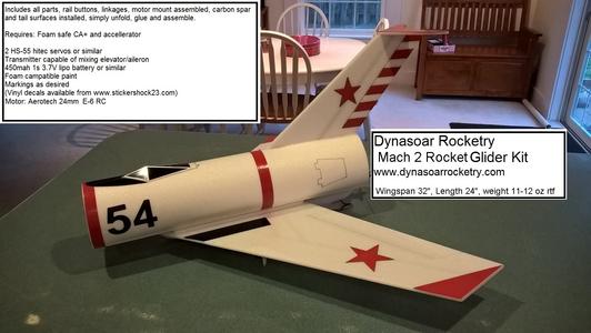
Mach 2 Rocket Glider Kit
This model is themed on the old Centuri Mach 10 rocket boosted glider kit. On this version nothing is ejected from the model. The tail was shorted slightly for stiffness and the wings moved forward slightly to compensate for lateral stability requirements. The canopy is printed on thick photo paper.
(This model requires two 12" servo extensions. I also recommend flying this on the Aerotech E-6 RC reload for the first several flights as it gives the slowest boost and allows you to trim the model if neeed.) Please refer to the notes on items needed for completion and flying,then read the instructions completely before starting assembly. The assembly photos are for general reference but may not include every step in the manual. CG location for rocket flight should be 11 1/2" from the front of the body tube. The front of the wing should be glued at 3 3/4" from the front of the body tube at the forward mark. (for electric flight start 3/16" forward of the rocket CG)
Stickershock23.com carries decals for US, Russian and German styles so you can customize it!
Welcome to the world of rocket boosted radio control gliders. This is not a model for a novice RC pilot, but anyone who is comfortable with RC flying of a medium speed model should be fine. Read through the instructions, look at the photos and be sure you understand the step before commiting to cutting or glue.
Mach 2 Rocket glider instructions
Identify all pieces, the kit should contain:
1 wing taped together
2 control horns.
2 pushrods
1 Horzontal stab
1 Vertical Stabilizer
1 Body Tube
1 foam keel.
2 foam wing reinforcing strips
2 foam motor mount reinforcing strips
Motor mount
Velcro(for battery and rx/bec attachment)
2 Rail buttons(2 washers, 2 collars, 2 screws, 2 rail button mounts) or 1 Launch lug and styrene strip for attachment
3M blenderm tape
1 wing spar.
Lead weight
Sheet with marking templates and canopy
Spare depron
Optional(if ordered):
Electric motor adapter
Notes before starting:
Reference to CA+ means foam safe CA+, normal CA+ will melt the foam! Normally you need to use accelerator to get the CA to set on the foam since there is nothing for it to soak into and activate.
You may use 220-320 grit sandpaper and a sanding block to slightly round the edges of the foam if you prefer that look. It will not markedly impact the flight performance either way. Be very careful and use a light touch, it is very easy to catch the foam on the edge of the paper and tear the foam. Do any sanding before assembly.
Epoxy is not needed in this model. Weight is critical and the model is designed for the thrust and flight loads. Weight in the rear end is bad and will require additional weight in the front of the model.
Assembly:
- Unfold the wing and glue the tape joint using CA+ and accelerator, make sure it is flat.
- Test fit, then glue the spar in place in the slot on the bottom of the wing. Tape over the spar with blenderm tape once the glue has set.
- Test fit the vertical fin in the slot, You may need to push the fin down slightly to get it to seat on the inside of the bottom of the tube.
- Apply glue to the bottom of the fin and glue it to the inside of the fuselage, use the alignment mark on the rear bottom of the tube as a guide to make sure it is straight.
- Apply a fillet of CA+ to the inside and outside of the tube/fin joint.
- Glue the motor tube at the bottom of the body tube and against the fin tab. Use the alignment mark at the rear of the tube and the front fin tab to make sure the motor tube is straight.
- Glue the two short reinforcing strips on either side of the motor tube and add a fillet of CA+ to help support the motor tube.
- Glue the wing to the bottom of the fuselage. Use the alignment line and the wing joint to ensure it is straight along the tube. Use the alignment marks at the front and rear to make sure the wing is in the right location. Set the model upright and make sure the fin is vertical and at 90 degrees to the wing.
- Round the front and rear of each wing reinforcing strip.Glue a strip on either side of the wing and fuselage joint. Add a Ca+ fillet to the wing/strip joint.
- Glue the horizontal stab onto the top of the vertical stab using the tab. Make sure it is 90 degrees to the vertical stab and reinforce with a slight fillet.
- Glue the keel to the bottom of the model. Note it should be flush with the rear and the front of the wing. Make sure the keel is straight and add a fillet on both sides.
- Use the included plastic plugs to mount the rail buttons. Put the rail button mounts 2" from either end of the keel. Make a starter hole with a screwdriver or similar round tool that is slightly undersized, and push the plastic plug into the keel. Try to keep it centered and straight, put a bit of CA+ underneath the plastic head before you push it all the way in. Use a screw, a plastic collar and a plastic washer to complete the rail button guide. You'll need to keep the collar centered when assembling as the screw is slightly undersized for the hole in the collar. Install the wing guard nylon pieces in front of each rail button. Make sure they are lined up with the rail buttons so that they do not bind on the rail. These guards help prevent damage to the rail buttons when landing on hard surfaces. If you land on grass you may omit these.
- NOTE if you have an earlier kit without the above pieces and with a styrene strip follow the below instructions to install your rail buttons.
- Use CA+ to glue the styrene strip on the bottom of the keel, centered between the two black lines. Have the dots facing up. This will reinforce the bottom of the fuse where the rail buttons will mount. If you are using a launch lug you can glue the strip to the side of the keel near the bottom.
- If you are using rail buttons, drill a small starter hole for each rail button screw in the styrene about an inch from each end(the dots mark approx. location) and screw in your rail buttons.
- Install the wing guard nylon pieces in front of and behind the rail buttons, glue this into the foam, not the styrene strip. Make sure they are lined up with the rail buttons if you use them and that they do not bind on the rail.
- Use CA+ to glue the styrene strip on the bottom of the keel, centered between the two black lines. Have the dots facing up. This will reinforce the bottom of the fuse where the rail buttons will mount. If you are using a launch lug you can glue the strip to the side of the keel near the bottom.
- If using a launch lug, glue it to the side of the keel on the styrene strip with CA just make sure the rod will clear any wiring.
- Cut out the canopy. Fold the canopy at each black line, fold so that the black lines will be in the underside of the canopy. Glue the tab at the front to form the shape. Once complete glue the canopy to the top of the model in the location you prefer, I glued mine about 2-2.5" from the front.
- Install the control horns into the elevons with CA+ in the pre-made holes. Apply CA+ on the top of the surface where the prongs poke through to lock them in place. Make sure these are installed securely.
The basic construction is now complete.
Radio Installation
Note: Your radio needs to be configured for Delta mixing, this means that the servo arms will move the same direction during elevator stick movement and opposite for aileron stick movement. Connect your servos to the receiver one in the aileron connection and one on the elevator connection and apply power. Use a servo arm at least 9/16” long and with holes small enough that there won’t be slop with the pushrod wire when installed. I use the hole furthest out on the servo arm, to maximize movement. On some servos there are a long two-ended servo arm, you can trim off one end if needed to get sufficient length. Zero out any trim settings on the transmitter. The model once the motor has burned out is nose heavy and flying wings lose pitch authority when nose heavy so you want as much up elevator travel for trim/flare as possible.
- Install a pushrod in the outermost hole of each control surface control horn. The pushrod should toward the fuselage side of the control horn. You may need to twist the wire back and forth to get it to go into the hole, it should be snug and slop free. It may be necessary to rotate the pushrod end to drill the hole large enough to fit, be careful not to puncture your finger. Be careful to support the control horn so that you do not break the glue joint in the control surface. It is snug but it will fit with patience.
- Connect a servo to each pushrod, the servo wire should be closest to the center and the output shaft is outboard toward the wing tip. If the wire is too tight, you can use twist an exacto knife in the servo arm hole to make it larger, but be careful and do not make it too large. Once connected, tape each servo in place so that the control surfaces are centered. Flip the model right side up and look at it from the rear. Moving the transmitter stick back(up elevator) should move both elevons up. Moving the transmitter stick to the right should move the right elevon up and the left elevon down. If you can’t get the servo reversing to give you the right polarity try swapping aileron/elevator inputs to the receiver or turning the servos over and swapping the servo arms to the other side of the output shaft. If that is correct, continue.
- Flip the model upside down and supported. The servos may be attached to the model using double back servo mounting tape(not included) or by directly gluing the servo to the wing with CA+ or a small amount of epoxy. Double back servo tape can loosen over time and with exposure to heat, I prefer to glue the servo in place. With the radio still on, put a small amount of glue on the servo, being careful not to get any near the output shaft. And set it in place on the model keeping the control surface centered. Do the same to the other side. Make sure the glue is set before continuing. The servo and pushrod should be at 90 degrees to the hinge line so that it moves easily and fully. The servo should not be glued to the blenderm tape as it won't adhere well.
- Flip the model back right side up. Make sure the control surfaces are centered, use trims if needed. Now measure the control surface movement. Full elevator movement should be 3/4” in each direction, aileron movement should be 1/2" in either direction. Since the model will be nose heavy, elevator elevon movement helps to give sufficient authority during glide.
- If you have a flap/elevator mix you can program up elevator to a switch setting. The model needs approximately 1/8" of down elevator for boost and 1/4” of up elevon during glide. If you can’t set the up elevator trim to a switch on your radio you’ll have to manually put in boost and glide trim which is hard to do while flying the model.
- Attach a 12" servo extension to each servo.
- Make a slot in the bottom of the wing/fuselage and pass the wires through to the inside and toward the front.
- Attach the servo wires to the receiver and make sure they are going the right direction. Tape down the servo wires to the wing and inside of the fuselage when done.
- Use the included Velcro to attach the receiver and battery to the model as far forward as practical. This allows you to be able to remove and replace the receiver if needed for repairs or for removing the servo wires. I attached the battery and receiver slightly up on the inside of the front of the model to allow me to put my nose weight in the bottom center of the fuse when balancing.
- Insert your heaviest loaded rocket motor into the motor mount
- Support the model at the balance point indicated for boost. I use two pencils with the eraser pointed up and held in place with a small hand vice. Place the model upside down on the pencil erasers on the balance point indicated in the kit spec sheet. Use the included lead weight at the front of the model to balance it.
- Do not try to fly the model with it balancing it behind this point. The adage is, a nose heavy model flies poorly, a tail heavy model flies once.
- If you paint the model, make sure you test it on scrap foam first.
- If you are going to paint the model, you can remove the receiver/bec and mask off the servos and Velcro strips on the model. Make sure no paint will get on the servo output arm. Make sure to test the paint on a scrap piece first to ensure it won’t melt the foam. I use Model Master(testors) or testors small rattle cans for painting directly on the foam.
- I used vinyl for the trim colors on my model. With the vinyl from stickershock23 it helps once applied to use a hair dryer on hot to soften the material and then push it down onto the model with a towel. It helps it confirm and stick much better, especially on painted surfaces.
- Use a black sharpie to add panel lines if desired.
- Re-install the receiver and battery
Flying: See the Instruction/Information link at the top for flying instructions Note this model uses a slight down trim for boost unlike the other models which use neutral controls for boost. Be ready on the first few flights to keep the model straight till you have the trims set perfectly.
Copyright © dynasoarrocketry.com. All rights reserved.
