
Radio Controlled Rocket Glider Kits
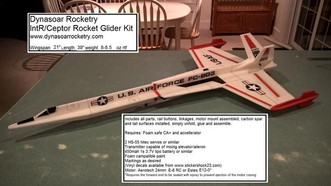
Updated IntR/Ceptor Rocket Glider Kit
The IntR/Ceptor is a futuristic deep space interceptor. It can be built ready to fly around 8-8.5 ounces avoiding registration as a drone under FAA guidelines. It has the lightest weight/highest boost of any of our kits and flies to over 700', even in windy conditions.
Please refer to the notes on items needed for completion and flying, then read the instructions completely before starting assembly. The assembly photos are for general reference but may not include every step in the manual.
CG location for rocket flight 7/16" forward from the wing LE/fuselage intersection
(for electric flight start 1/4" forward of the rocket CG)
Welcome to the world of rocket boosted radio control gliders. This is not a model for a novice RC pilot, but anyone who is comfortable with RC flying of a medium speed model should be fine. This model has a very moderate glide and slow landing speed. Read through the instructions, look at the photos and be sure you understand the step before commiting to cutting or glue.
IntR/Ceptor Rocket glider instructions
Identify all pieces, the kit should contain:
Wing with spar and elevons intsalled
2 pushrods
2 spars(on older kits the spars are already installed in the wing)
2 Vertical Stabilizers(left and right)
Forward FuselageTop view
Fuse bottom doubler(rectangular piece)
Upper fuselage side view(taped together)
Lower fuselage side view(taped together)
4 wingtip pod pieces.
Motor mount
Velcro(for battery and rx/bec attachment)
2 Rail buttons(2 washers, 2 collars, 2 rail button mounts, 2 screws) or 1 Launch lug and styrene strip for attachment
3M blenderm tape
Lead weight
Spare depron
Optional(if ordered):
Electric motor adapter
Notes before starting:
Reference to CA+ means foam safe CA+, normal CA+ will melt the foam!
You may use 320 grit sandpaper and a sanding block to slightly round the edges of the foam if you prefer that look. It will not markedly impact the flight performance either way. Be very careful and use a light touch, it is very easy to catch the foam on the edge of the paper and tear the foam.
Epoxy is not needed in this model. Weight is critical and the model is designed for the thrust and flight loads. Weight in the rear end is bad and will require additional weight in the front of the model.
Assembly:
- Unfold the fuselage top side view and glue the joint at the tape seam with CA+ and accelerator. Repeat with the fuselage bottom side view.
- CA+ the bottom fuselage doubler onto the fuselage bottom side view, between the two black marks. Make sure the bottom of the pieces are even. This needs to be flat.
- Unfold the wing and glue the front joint at the tape seam with CA+ and accelerator.
- Glue the two small spars into the bottom of the wing in the grooves and then tape over with blenderm tape. This step may be already done on some kits.
- Place the wing and forward fuselage top view upside down on a table. Tape the forward fuselage top view in place against the wing, make sure it is straight, the top should be down, use 3m blenderm tape. Flip the model with the top markings up, then glue the joint together using CA+ and accelerator.
- Test fit the top fuselage side view into the top of the fuselage/wing. Be careful to not break off the tabs. The foam compresses slightly so it is ok to press them in place. Once aligned perpendicular to the wing and ensuring it is straight with a straight edge, apply a bead of CA+ to both sides of the joint and use accelerator to set it.
- Flip the wing upside down. Carefully insert a pushrod into each control horn in the outermost hole. The pushrod goes in from the inboard side. You must do this now because it is hard to do once the bottom fuselage side view is in place. Please handle the model carefully and do not snag the wires on anything, you may want to tape them down to the control surface for now. You may need to twist the wire back and forth to get it to go into the hole, it should be snug and slop free. It may be necessary to rotate the pushrod end to drill the hole large enough to fit, be careful not to puncture your finger. Be careful to support the control horn so that you do not break the glue joint in the control surface. It is snug but it will fit with patience.
- Test fit the assembled lower fuselage side view piece into the notches in the wing and fuse. Make sure it fits well. Once happy with the fit and making sure it is straight down the middle of the wing, apply a bead of CA+ on both sides and use accelerator to set the glue. Make sure the fuselage does not get any twist or warp.
- Test fit the motor mount into the rear of the model. It is useful if you have a motor casing in the tube to hold it round. Make sure it fits, Make sure the fuselage pieces are aligned straight and the motor tube is aligned with the centerlines of the model. Make sure the motor hook is not blocked by the foam and can be reached to release the motor. I put the motor hook at the lower right quadrant when looking at the rear of the model, at about the 4:30 position, so it is not visible. When happy, use CA+ and make a bead on each joint and set it with accellerator. Make sure the motor tube is attached well but don’t overdo it and don’t use epoxy, tail weight is a killer and there isn’t much force on the motor tube during launch. The foam is plenty strong enough to support the forward thrust and no thrust ring is needed. I’ve flown many flights and the forward foam has never melted or failed.
- Flip the model rightside up.
- CA+ the vertical stabs onto the model. They are pre-sanded at an angle. The angle isn’t really critical as long as each side is approximately the same. The bottom of the stab should rest on the top of the motor tube and be lined up straight with the fuselage. Repeat on the other side.
- CA+ the wing tip pods to the top and bottom of each wing tip. Make sure they are straight and parallel to the fuselage.
- Use the included plastic plugs to mount the rail buttons. Mount the rail buttons about 2" from either end of the doubled portion of the bottom of the fuse. Make a starter hole with a screwdriver or similar round tool that is slightly undersized, and push the plastic plug into the keel. Try to keep it centered and straight, put a bit of CA+ underneath the plastic head before you push it all the way in. Use a screw, a plastic collar and a plastic washer to complete the rail button guide. You'll need to keep the collar centered when assembling as the screw is slightly undersized for the hole in the collar. Install the wing guard pronged nylon pieces in front of each rail button. Make sure they are lined up with the rail buttons so that they do not bind on the rail. These guards help prevent damage to the rail buttons when landing on hard surfaces. If you land on grass you may omit these.
- The basic construction is now complete.
Radio Installation
Note: Your radio needs to be configured for Delta mixing, this means that the servo arms will move the same direction during elevator stick movement and opposite for aileron stick movement. Connect your servos to the receiver one in the aileron connection and one on the elevator connection and apply power. Use a servo arm at least 9/16” long and with holes small enough that there won’t be slop with the pushrod wire when installed. I use the hole furthest out on the servo arm, to maximize movement. On some servos there are a long two-ended servo arm, you can trim off one end if needed to get sufficient length. Zero out any trim settings on the transmitter. The model once the motor has burned out is nose heavy and flying wings lose pitch authority when nose heavy so you want as much up elevator travel for trim/flare as possible.
- Install the other end of the pushrod to the servo output arm, again making sure the servo wire is toward the fuselage side of the model. If the wire is too tight, you can use twist an exacto knife in the servo arm hole to make it larger, but be careful and do not make it too large. Once connected, tape each servo in place so that the control surfaces are centered. Make sure the pushrod won’t catch on the leading edge of the control surface. Flip the model right side up and look at it from the rear. Moving the transmitter stick back(up elevator) should move both elevon TE’s up. Moving the transmitter stick to the right should move the right TE of the elevon up and the left one down. If you can’t get the servo reversing to give you the right polarity try swapping aileron/elevator inputs to the receiver or turning the servos over and swapping the servo arms to the other side of the output shaft. If that is correct, continue.
- Flip the model upside down and supported. The servos may be attached to the model using double back servo mounting tape(not included) or by directly gluing the servo to the wing with CA+ or a small amount of epoxy. Double back servo tape can loosen over time and with exposure to heat, I prefer to glue the servo in place. With the radio still on, put a small amount of glue on the servo, being careful not to get any near the output shaft. And set it in place on the model keeping the control surface centered. Do the same to the other side. Make sure the glue is set before continuing. Again, make sure the pushrod is aligned straight and will not catch on the LE of the control surface.
- Flip the model back right side up. Make sure the control surfaces are centered, use trims if needed. Now measure the control surface movement. Full elevator movement should be 1” in each direction. Aileron movement should be about about ¾”. With modern radios you can typically set these movements. Since the model will be nose heavy, extra elevator movement helps to give sufficient authority during glide. Set up dual rates with lower movements if you are worried but boost with higher settings till you are comfortable.
- If you have a flap/elevator mix you can program up elevator to a switch setting. The model needs approximately 1/4” of up elevon during glide. Boost will use completely neutral settings for the first flight. If you can’t set the up elevator to a switch on your radio you’ll have to manually put in glide trim which is hard to do while flying the model.
- Once complete you can tape the servo wires to the wing using the blenderm tape. Use the included Velcro to attach the receiver to the model. Mount the receiver as far forward as it can go. This allows you to be able to remove and replace the receiver if needed for repairs or for painting.
- Use the Velcro to attach the battery
- Insert your heaviest loaded rocket motor into the motor mount.
- Support the model at the balance point indicated for boost. I use two pencils with the eraser pointed up and held in place with a small hand vice. Place the model upside down on the pencil erasers with the erasers just behind where the leading edge of the wing intersects the top view of the fuse as indicated in the plans. Place stick on lead weights near the nose of the model to balance it.
- Do not try to fly the model with it balancing it behind this point. The adage is, a nose heavy model flies poorly, a tail heavy model flies once.
- If painting, make sure to test the paint on a scrap piece first to ensure it won’t melt the foam. I use Model Master(testors) or testors small rattle cans for painting directly on the foam. Model master flat black is perfect.
- Use a black sharpie to add panel lines if desired.
- You can use self adhesive vinyl/mylar decals or lettering
Flying: See the Instruction link at the top of the page for generic flying instructions.
Copyright © dynasoarrocketry.com. All rights reserved.
