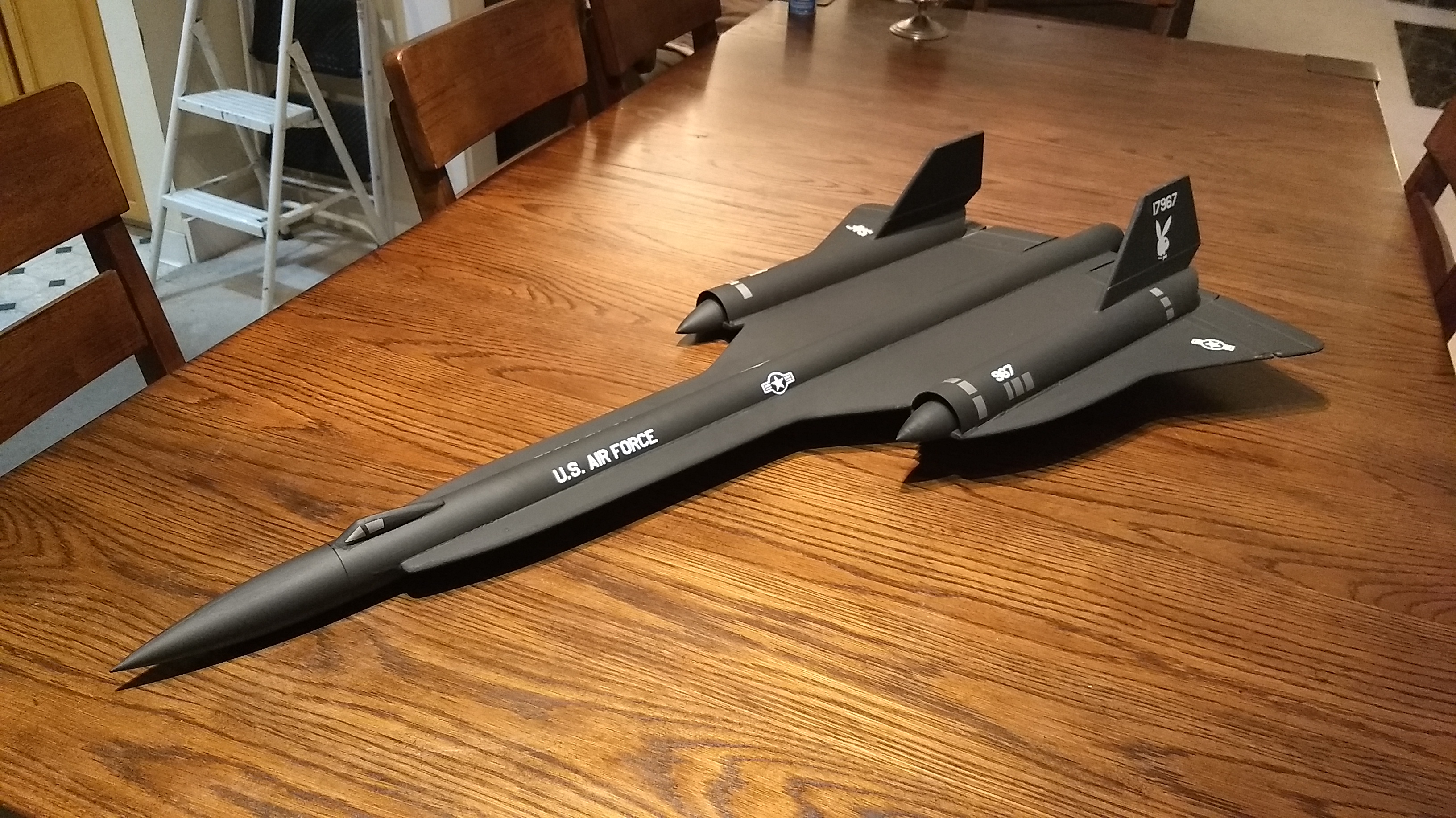
The YF-12 RC rocket glider kit
The YF-12 RC Rocket glider kit is designed after the prototype interceptor version of the A-12/SR-71. It comes with white BMS tubing for the body and engine nacelles and Depron wing and tail surfaces. You will need two 8-11 gram type servos, a receiver, and a small 500mah single cell lipo battery and two 18″-20″ servo extensions. You will need a transmitter with delta or elevon mixing. Foam safe CA+ is the only correct glue to use for all construction on this model. Any other adhesive will add weight in the wrong place, and reduce flight performance. Please refer to the General instructions for all kits tab above, then read these instructions completely before starting assembly. For 24mm Composite reloads or single use E-6 motors. Wingspan 21.5″, length 39.5″(about 1/32 scale) weight 10.5 oz rtf. High quality cut vinyl decals available Here
This kit is more of a builders kit than my others, but still not complicated if you follow the directions.
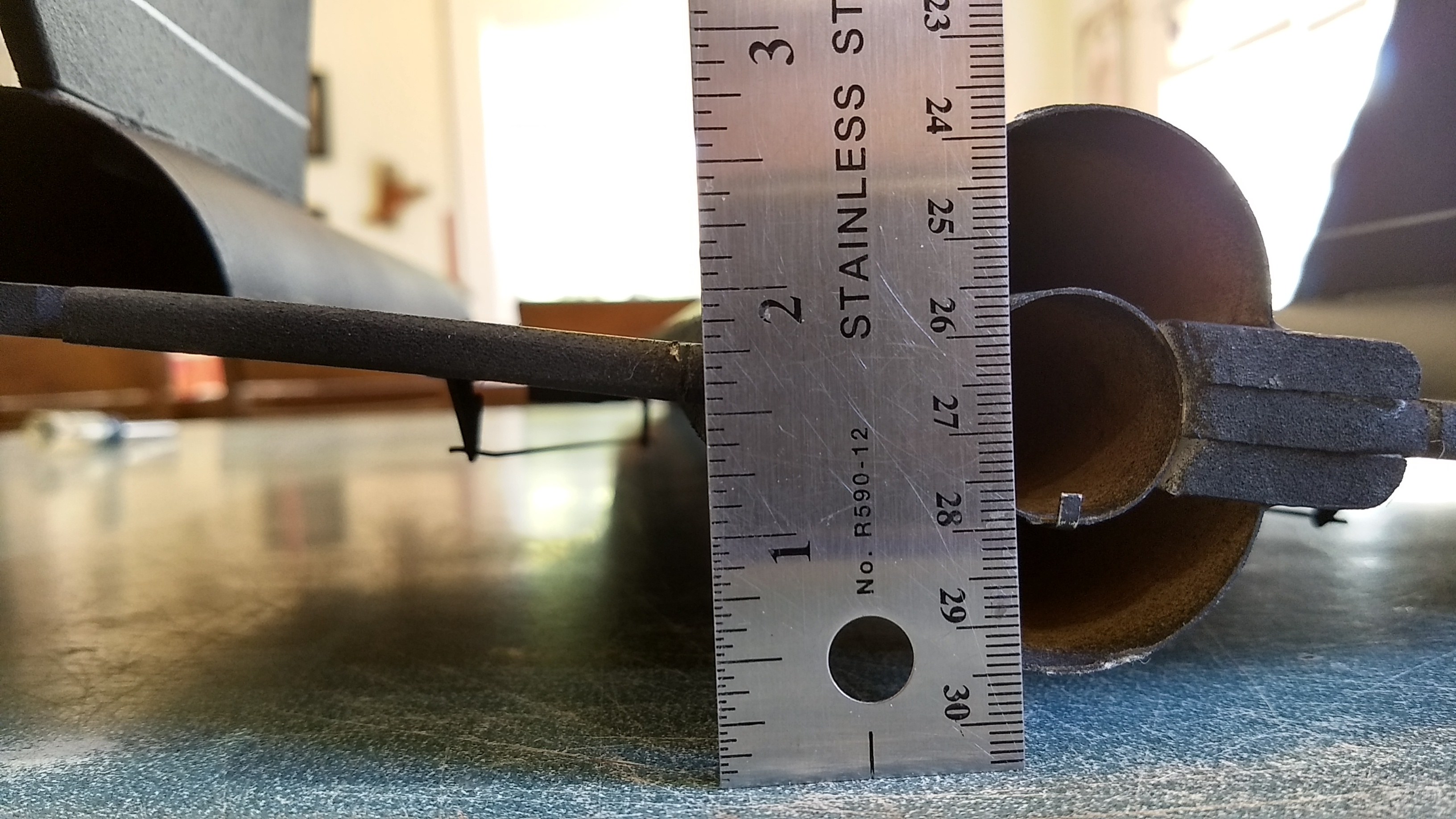
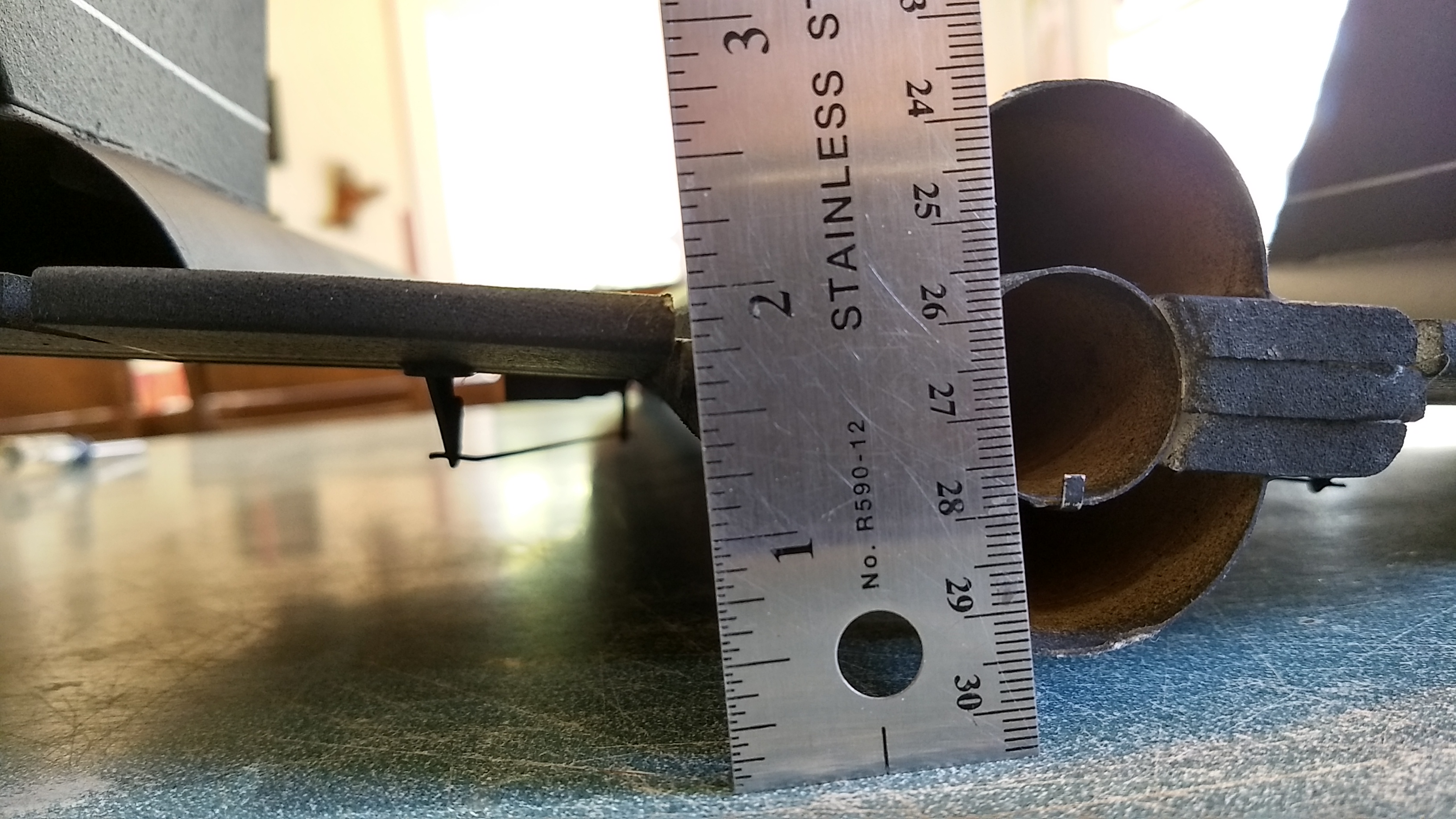
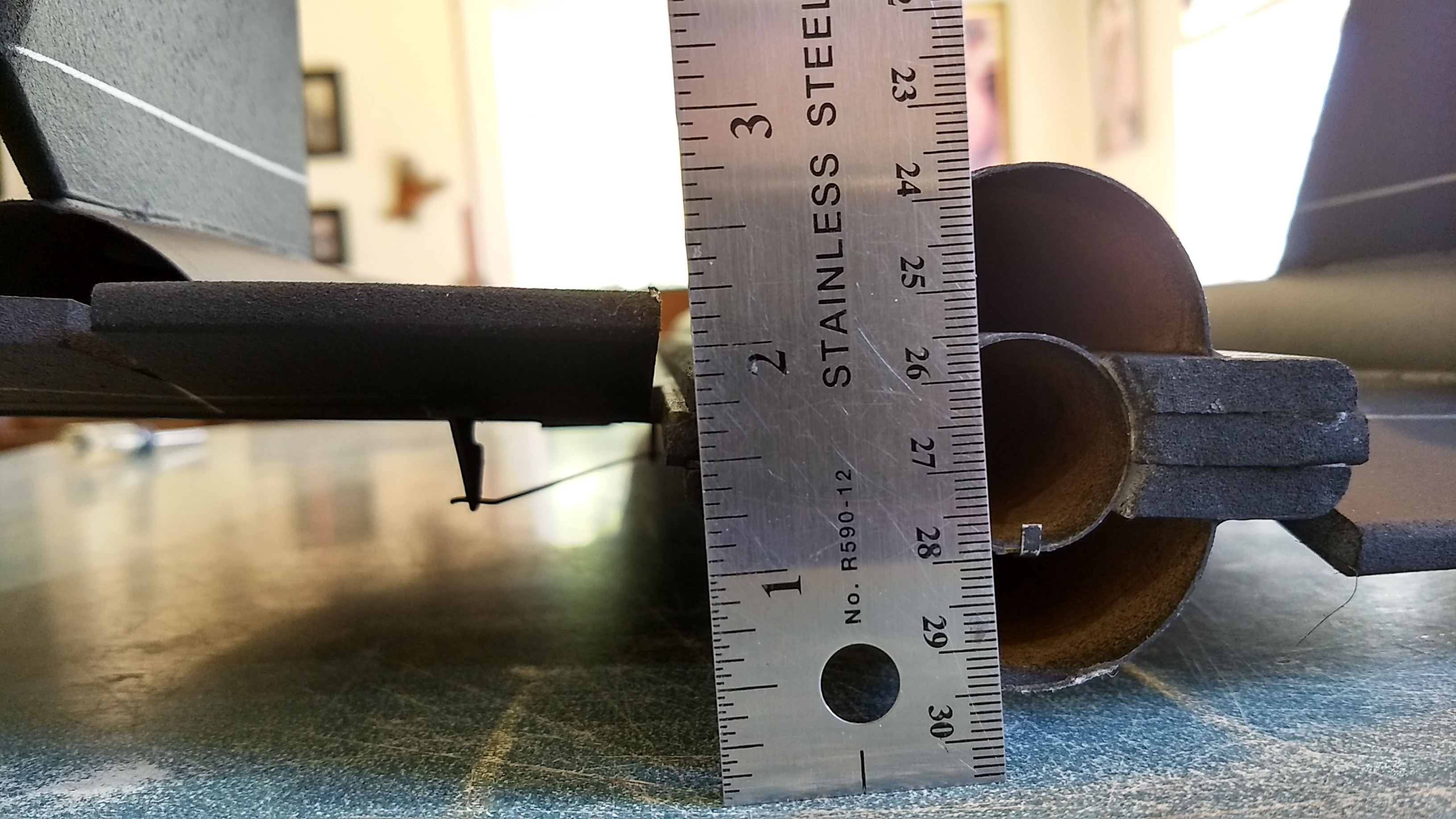
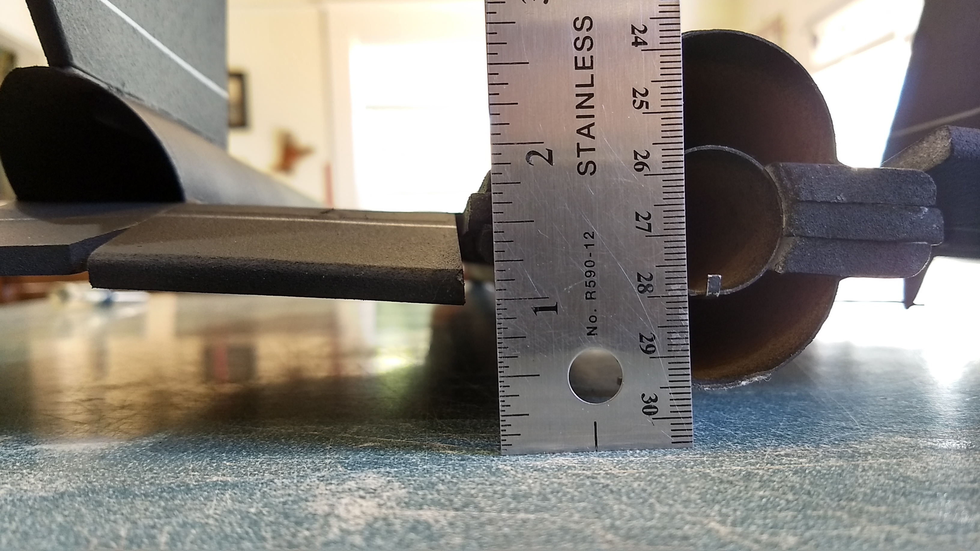
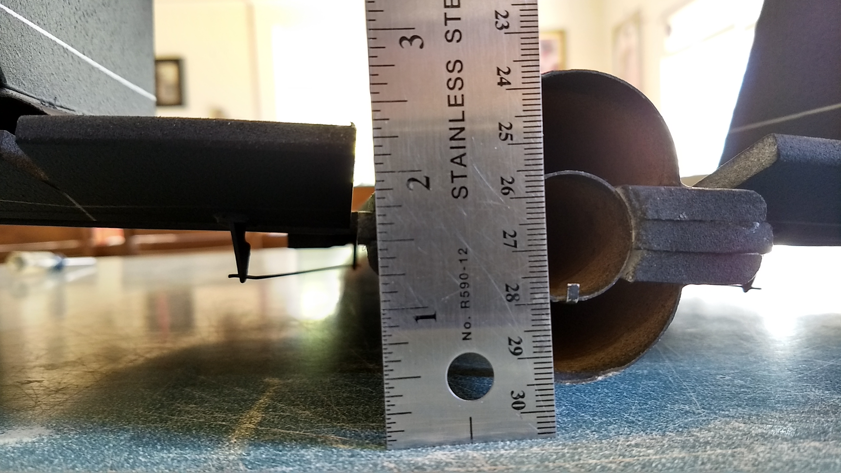
CG location for rocket flight: 1″ back from the the front of the nacelle tubes.
When I released this kit, I was contacted by Ray Scalise, the original Hughes FCO on the YF-12 AIM-47 Falcon Missile test firings, he sent me some notes from his experience: RayScaliseYF-12
Unpacking your kit:
The kits are packed to protect them in shipping, but the contents are fragile so unpack carefully. Carefully cut the tape holding the tubes in the box, then unwrap/lightly cut the plastic wrap to free the tubes, the spar may be packed in the tubes and the baggie with the little parts and nose cone will be in the tubes as well. Carefully cut the tape holding the cardboard wing protector in the box and carefully remove it, don’t pull hard or bend it. Then carefully cut the tape holding the cardboard top piece to the bottom. There may be some sticky tape holding the cardboard to the bottom cardboard piece, carefully peel it being sure not to bend anything. Once the top cardboard is free you can see the foam wing/tail parts, there are little fragile pieces in here, so unwrap carefully. It may be best to use an exacto to lightly cut the plastic wrap and carefully remove it without cutting into the foam. Make sure everything is free before you remove the pieces to avoid breaking anything. Kits contain one or two scrap pieces for repairs if you damage anything in construction or flight, just cut and patch in a spare piece of the foam if needed using foam safe CA+. The tubes may look a bit smudged or have some gray marks, this is due to the aluminum angle I use for cutting the slots, if it bothers you you can use a soft eraser to remove it, but since it will be painted black, it won’t really matter.
Welcome to the world of rocket boosted radio control gliders. This is not a model for a novice RC pilot, but anyone who is comfortable with RC flying of an aileron controlled medium speed model should be fine. Read through the instructions, look at the photos and be sure you understand the step before commiting to cutting or glue.
Identify all pieces, the kit should contain:
1 wing taped together
2 vertical stabilizers
2 narrow foam strips.
1 rear body tube with holes for rail buttons
1 front body tube without holes.
1 nacelle tube(will be split and used for the right and left nacelles.
2 control horns w/pushrods
Velcro(for battery and rx/bec attachment)
3M blenderm tape
1 coupler
Nose cone
2 intake cone lower plates
2 intake cone upper plates
2 Intake cone paper wraps
3 foam cockpit pieces.
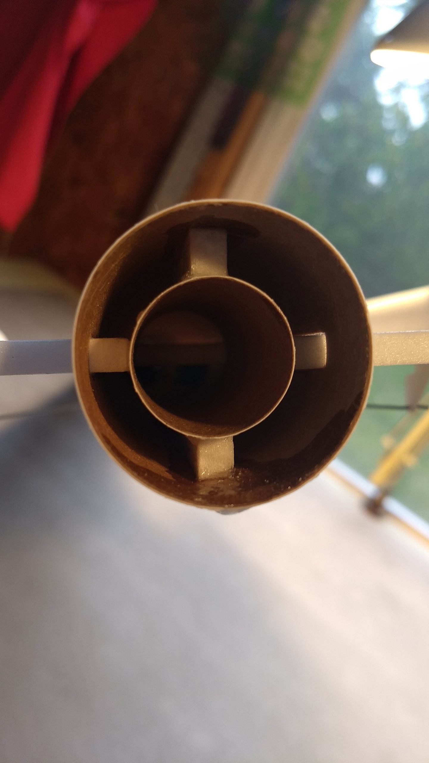
motor tube
long and short carbon spars.
2 rail buttons/t-nuts and screws
Lead weight
Spare foam (for testing paint, glue, and sanding the edges to see how it behaves)
Assembly:
- Look at all parts and understand what pieces go where.
- Unfold the main wing and glue the taped joints. The forward joint is taped only on half of the cut so that it can fold to fit into the box.
- Glue in the two spars into the premade slots on the bottom of the wing and then tape over with blenderm tape.
- You may use 320 grit sandpaper and a sanding block to round the edges of the foam before further assembly. Round all edges of the wing at this time except for the flat part where the intake cone will be mounted. Go slowly and take your time. Round the leading and trailing edges of the vertical stabilizers at this time as well.
- Once the sanding is finished wrap blenderm tape completely around the forward horizontal wing joint near the neck, it will help support and hide the joint.
- If your rail buttons are not pre-installed, install them at this time. Install the rail buttons into the tube with the pre-punched holes. This will be the rear tube. I found it is possible to install the rail buttons through the slot in the tube and using a stick to hold the t-nut in place while you tighten them down. The T nut goes inside the tube, then a plastic washer, plastic collar and plastic washer go on the outside of the tnut shaft and held in place with the included screw. Make sure they are snug but don’t over tighten as it will deform the tube.
- The body tubes are pre-cut for the wing slot except for where the coupler goes. When gluing the coupler, you may want to use a slower setting glue so you have time to work, if you use the CA, make sure you test fit the coupler into both tubes and make sure they fit easily. Glue the coupler into the front of the rear tube(the front of the rear tube has the arrow marked on the bottom). It should be glued about 2″ into the tube, about where it hits the t nut you installed. Glue the front body tube in place onto the coupler, the front tube is also marked with an arrow on the bottom, make sure you align the arrows so that the wing slots are correctly aligned.
- Once the glue is set, using multiple light cuts slowly cut the body tube slot through the tube and coupler to make a complete slot. Go slow and make multiple passes a little at a time. Test fit the a spare piece of foam into the slot to make sure the wing will install easily.
- Test fit and slide the wing into the body tube slot making sure it is centered front and rear and the rail buttons are on the same side as the visible spars(on the bottom) **Note the body tube with the rail buttons will be toward the rear of the model. Once centered, place the model upside down on a flat surface so that the rail buttons are up and glue fully along the body tube bottom to secure it in place. The tube tends to flatten once it is cut so you may need to pinch the tube slightly as you glue and use accellerator a bit at a time to make sure it stays round in the middle and makes contact with the wing. Flip over and lay the front portion on something flat and glue the top tube starting with the neck section. Since the rail buttons are in place you will need to be careful when you glue the top rear that you do not deform or bend the wing as you glue.
- Glue the two pushrods/control horns in the bottom of the wing in each control surface in the pre-punched holes using CA+. Apply CA+ to the top of the control surface on the prongs from the control horns to capture them in place. Set with accelerator. Note in the picture how the control horns face, the flat part of the control horns faces forward so that the holes that the pushrod go in are even with the hinge line.
- Your radio needs to be configured for Delta mixing, this means that the servo arms will move the same direction during elevator stick movement and opposite for aileron stick movement. Connect your servos to the receiver one in the aileron connection and one on the elevator connection and apply power. Use a servo arm at least 9/16” long and with holes small enough that there won’t be slop with the pushrod wire when installed. I use the hole furthest out on the servo arm, to maximize movement. On some servos there are a long two-ended servo arm, you can use this arm and trim off one end. Zero out any trim settings on the transmitter.
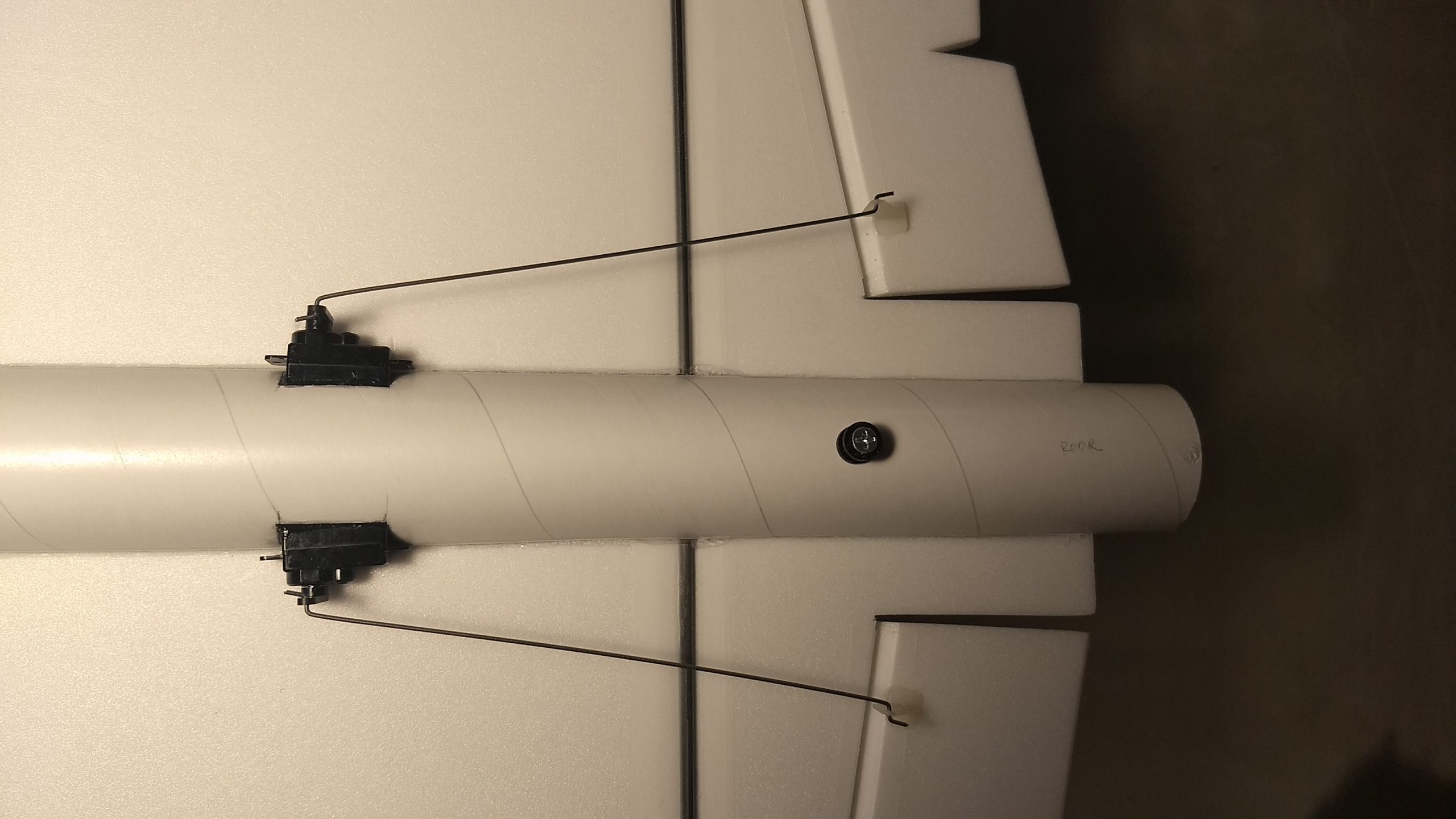
- Connect a servo to each pushrod. If the pushrod is too tight, you can use twist an X-Acto knife in the servo arm hole to make it larger, but be careful and do not make it too large. The servo arm will be facing away from the body tube and the servo control wire will be facing forward. Once connected check control surface direction. Flip the model right side up and look at it from the rear. Moving the transmitter stick back(up elevator) should move both elevons up. Moving the transmitter stick to the right should move the right elevon up and the left elevon down. If you can’t get the servo reversing to give you the right polarity try swapping aileron/elevator inputs to the receiver or turning the servos over and swapping the servo arms to the other side of the output shaft. If that is correct insert the screw to hold the servo arm in place.
- Flip the model upside down. Mark where the servo will sit in the body tube and mark and cut a pocket to fit, make sure the servo will fit into the pocket and the control surface will stay level.
- Attach a servo extension to each servo long enough so that it will go the full length of the body tube and out the front to allow you to connect it to the receiver. Route the servo wire forward and reconnect to the receiver.
- With the radio still on, put a moderate amount of glue on the servo, being careful not to get any near the output shaft, and set it in place on the model in the pocket keeping the control surface centered. Do the same to the other side. Make sure the glue is set before continuing.
- Attach the receiver and battery into the nose cone using the supplied velcro.
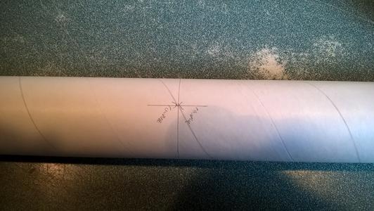
- Glue the two foam strips onto the motor tube on the two pencil lines that are opposite each other.
- Test fit the motor tube in place, sand the two foam strips a little at a time till the tabs will fit into the rear of the model with the tabs straight up and down. The sides of the motor tube are centered in the cutout in the wing. The motor tube doesn’t need a lot of glue to hold it in place.
- Glue a triangular lower intake cone foam piece to one of the the longer upper intake cone strips so that the triangle shapes are aligned.
- Cut out the paper intake cone shrouds.
- Glue one side of the paper wrap onto the side of the foam triangle shaped assembly so that the notch aligns with the notch/step between the two pieces at the rear. Glue so that the glossy side without printing will be visible. Gently wrap the paper around and glue to the other side making a half cone and glue to the other side again with the notch aligned with the step in the foam asssembly. Run CA on the inside corners and tip as well. Trim the foam tip at a slight angle if there is any excess to make it look clean. Repeat for the other side.
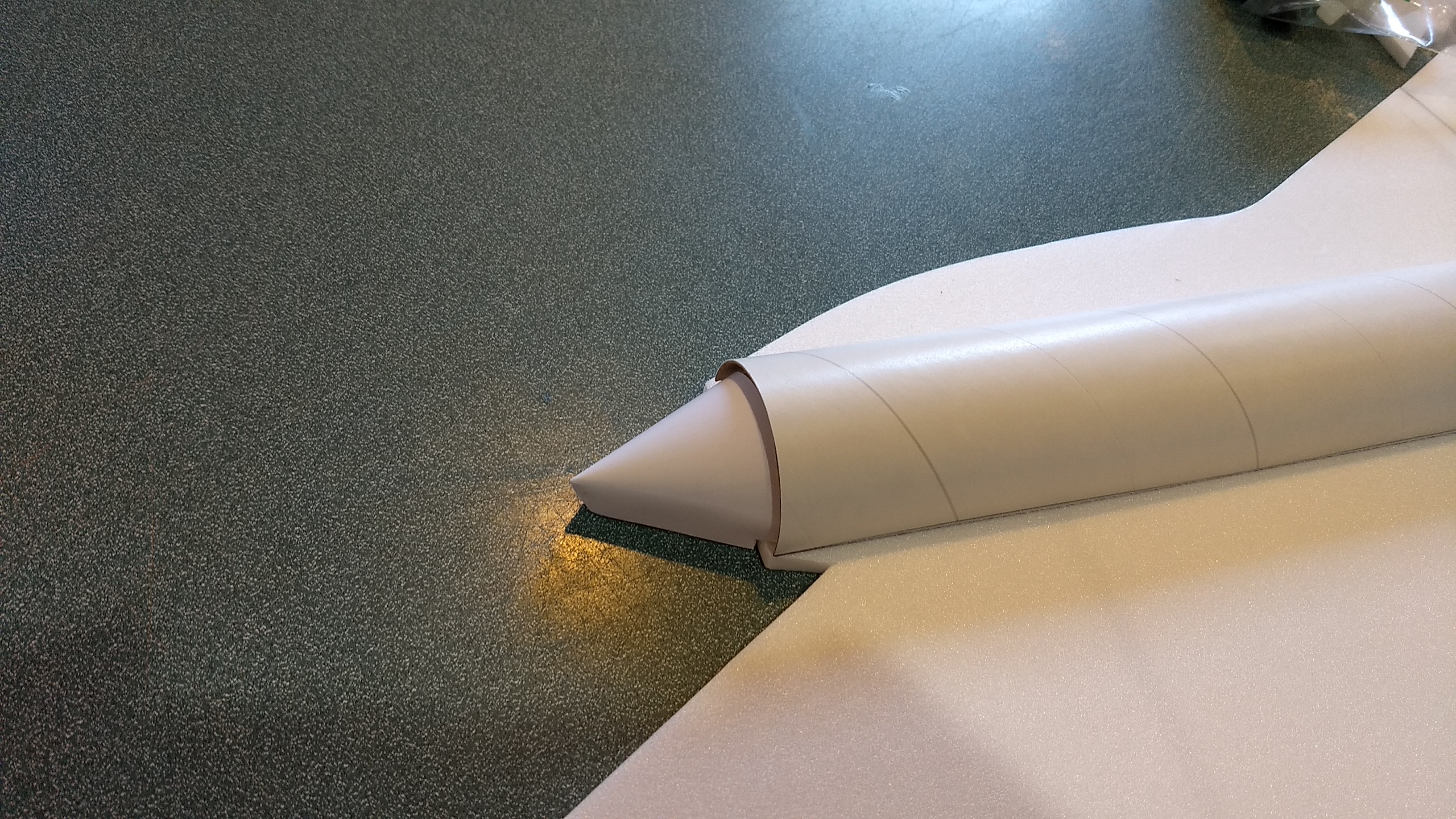
- Glue the intake cones on each wing, so that step is flush with the front of the wing and the cone is approximately 1/16″ from the marked nacelle tube wing line so that the nacelle tube can fit over the cone.
- Find the 2″ diameter pre-marked body tube with the tail slots pre-cut. Carefully cut the tube on both sides on the long pencil marks to make two halves using an exacto making multiple light small cuts, take your time.
- Lay one side of the wing on a table edge and supported so that it is flat.
- Look at the two pieces of nacelle tubing. There is a left and a right. They are marked on the tubes and the slot for the vertical stab will be inward. If you have these swapped the elevon won’t have proper clearance to move.
- Glue the correct nacelle tube in place. The font of the nacelle tube is even with the front of the wing and the rear must allow the elevon to move fully. There is a line on each wing half for gluing the nacelle. IT IS CRITICAL the first edge is glued on the line otherwise the nacelles may not be straight and the vertical stabs will have an undesired rudder angle built into them!! Glue the other edge in place.
- Repeat for the other side. Use accelerator to set the glue as you go.
- Glue the two vertical stabs in place in the slots. The stabs angle inward, it isn’t critical the absolute angle just try to get both sides approximately the same. Reinforce the joint on both sides with a CA fillet on the inside and outside of the tube, use accellerator to set the glue before proceeding.
- Glue the cockpit pieces together. Sand the assembly to shape using the photos as a guide. Wrap sandpaper around the front of the body tube and sand the bottom of the cockpit so that it will conform to the tube. Glue in place so the front of the cockpit is even with the front of the tube.
- Attach the flight battery using velcro to the inside of the nose cone.
- Paint the model using ONLY testors or model master enamel spray paint or Krylon short cuts small rattle can spray paint. This is the only paint I recommend. I’ve used testors and model master flat black. Mask off the rail buttons and the servo output arms to prevent paint from getting on them. Do not spray too close to the model. Use many light coats and do not spray heavy. I apply a coat to all the edges of the foam first since it tends to soak into the sanded exposed edges and look lighter, then apply light coats till the model is covered. Paint adds weight, use just enough to get a nice even finish. I used slightly more than one can of flat black to complete each prototype, and that added exactly 1/2 ounce to the model.
- You can use a silver sharpie to add panel lines or accents if you wish. The real YF-12 had a white cross painted on the bottom of the aircraft during the speed record runs for visibility, you may use vinyl trim or paint to do the same to help with orientation.
- If you use the stickershock decals, after applying them use a hot hair dryer to soften them and press down with your finger to make them conform to the foam/paint better.
- Install your loaded motor.
- Support the model at the balance point indicated for boost. Add weight as required to balance into the nose. Hold it in place with the foam safe CA. Do not try to fly the model too nose or tail heavy. Remember, a nose heavy model flies poorly, a tail heavy model flies once. I added a little at a time and re-checked often till it was just balancing slightly nose down. Do not just use all the shot included or you will be nose heavy most likely.
- Set up your throws and trims: The model uses approx 5/8-3/4″ up and down elevator throw and 1/2″ left and right aileron throw. It is quite roll sensitive on boost so you may tone this down as needed. For boost I used zero control trim but you may need some depending on how your model is built, and for glide I’m using about 3/16 of up trim or a slight bit more. I put this trim onto my flap switch so that I can go from boost to glide trim with the flip of a switch, you can also use a flight mode with independent roll and pitch trim to do the same function. Make sure when you launch you are in boost trim or it will be a very short flight.
Flying: Be ready on the first few flights to keep the model straight till you have the trims set perfectly for boost and glide. Try to do initial flights in dead calm conditions. You need to be ready to react quickly to keep it boosting straight up or slightly away from you. Keep the wings level. Count to 7 and start to push the model over level as the motor burns out and it slows down. Then click in the up trim. Avoid drastic bank angles which cause you to lose altitude and make it easy to lose orientation. Gently fly around, and set up for landing into the wind when about 100′ high. The model will rock the wings if you start to get too slow, if this happens push forward on the stick slightly. The decent rate is very predictable, keep some speed up so you don’t stall, and keep the wings level as it decends and gently flare just before touchdown.
-

- Kit Parts
-
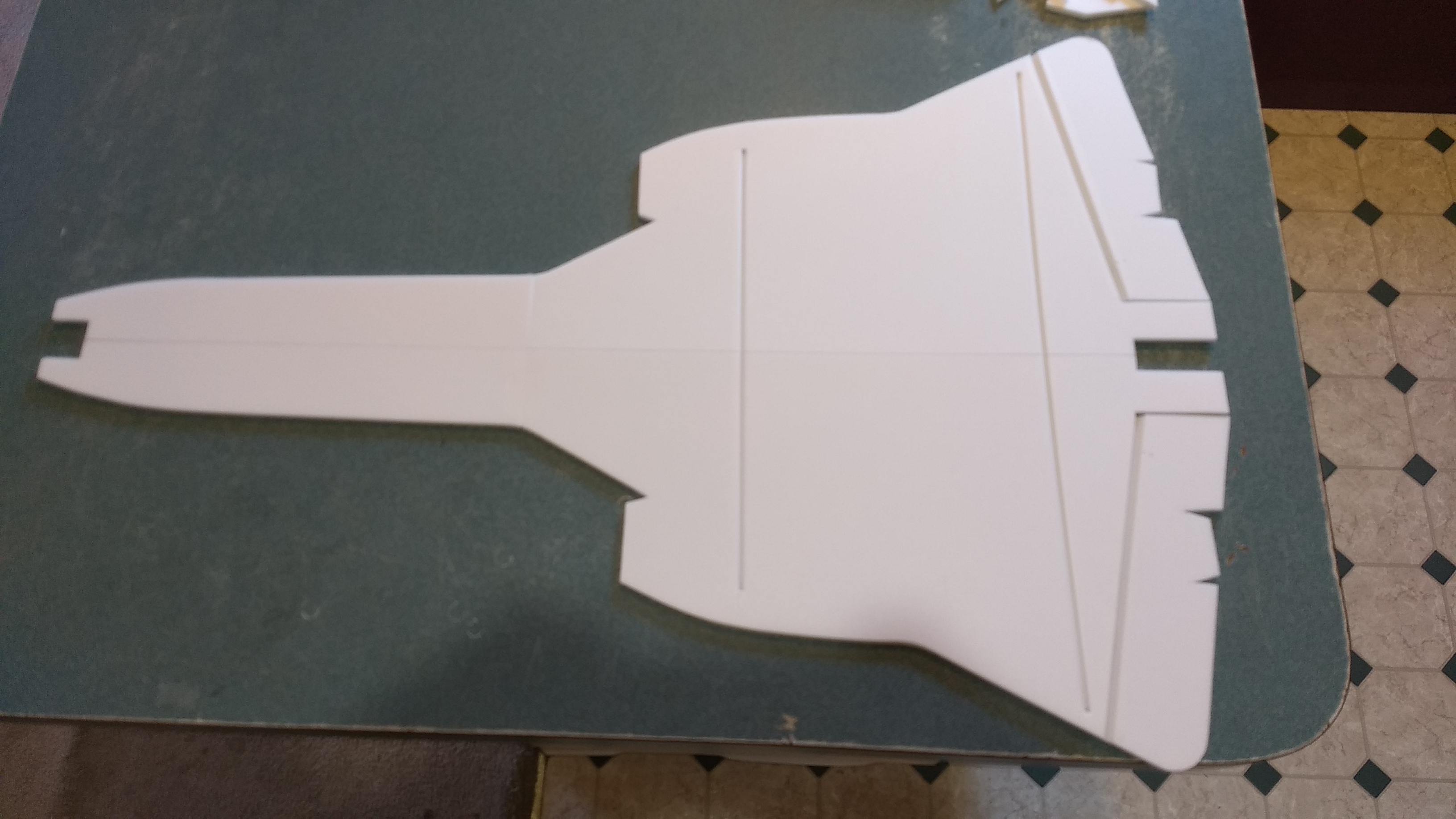
- Unfold the wing and glue the taped forward and middle joints
-

- Glue in the two spars then tape over with blenderm tape, sand the edges of the wing round, then tape around the forward joint fully to reinforce it.
-
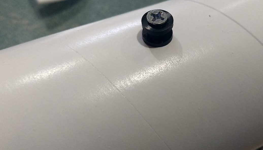
- Install the front and rear rail buttons
-
- Join the two body tubes so that the alignment arrows are aligned.
-
- Complete cutting slot for wing
-
- Test slot for fit using scrap foam
-
- Test fit then glue the wing into the body tube keeping front and rear centered, start with the bottom.
-
- flip over and glue the top of the body tube to the wing.
-
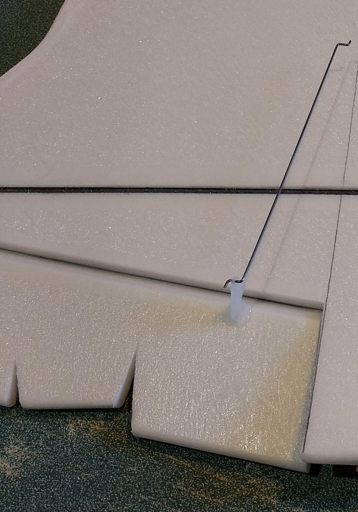
- Glue the control horns on the bottom of each surface, note the pushrod is closest to the center of the model.
-
- Glue the top of the control horn prongs to lock them in place
-
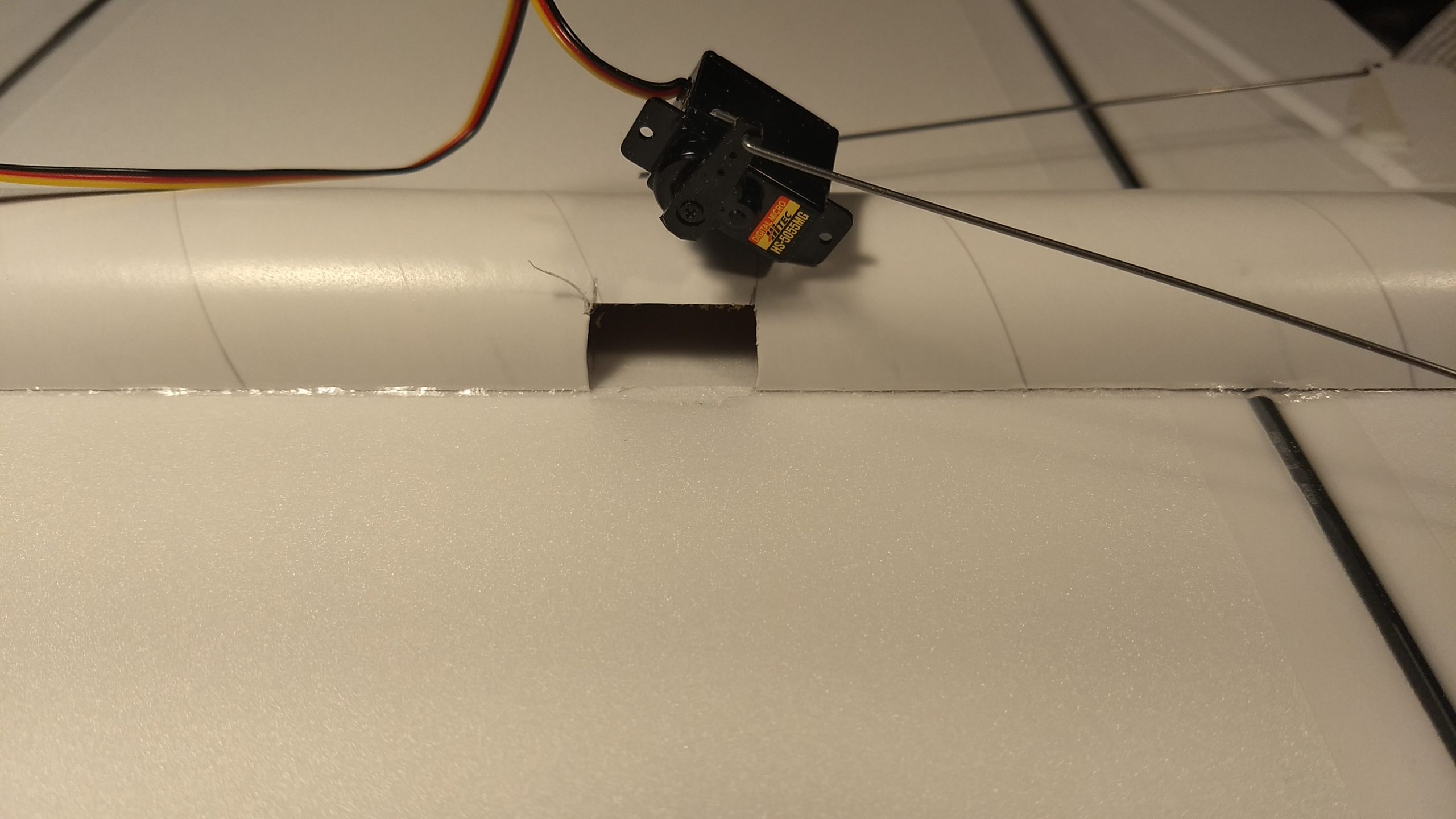
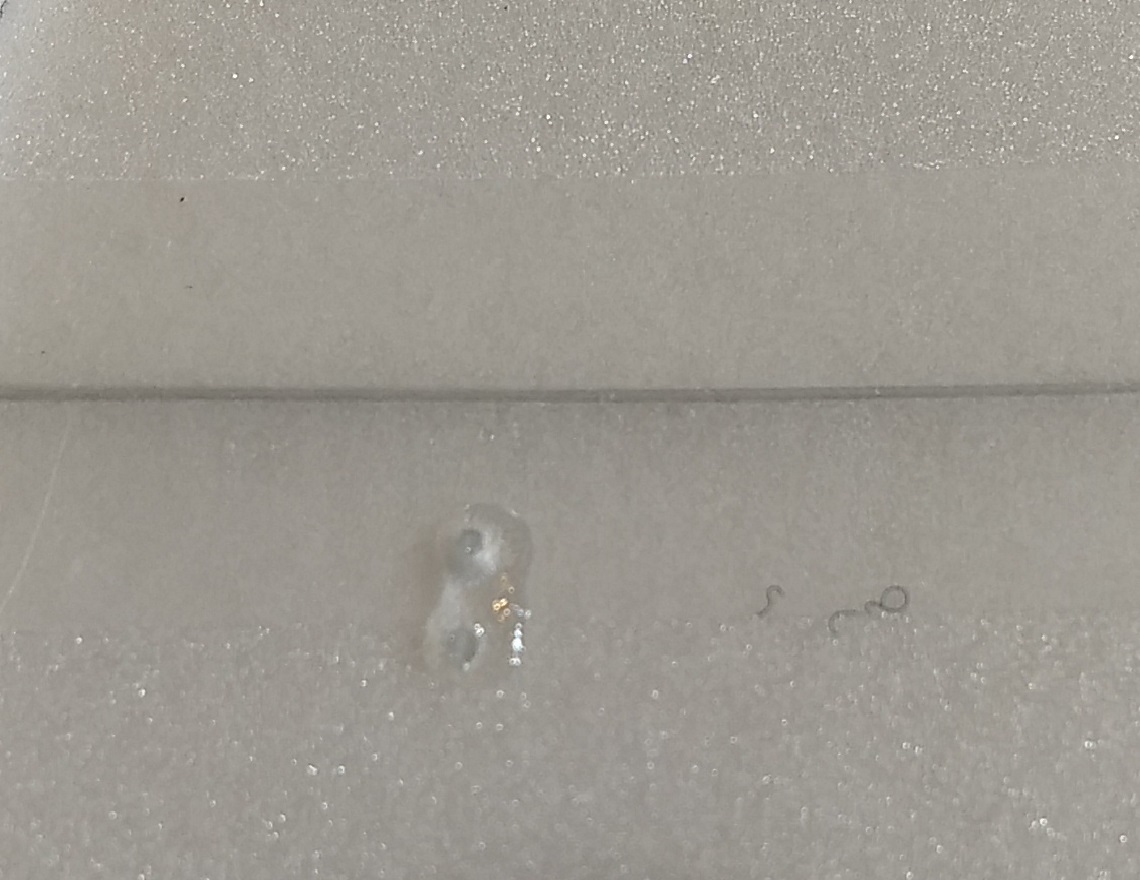
- Cut a pocket in the body tube for each servo
-
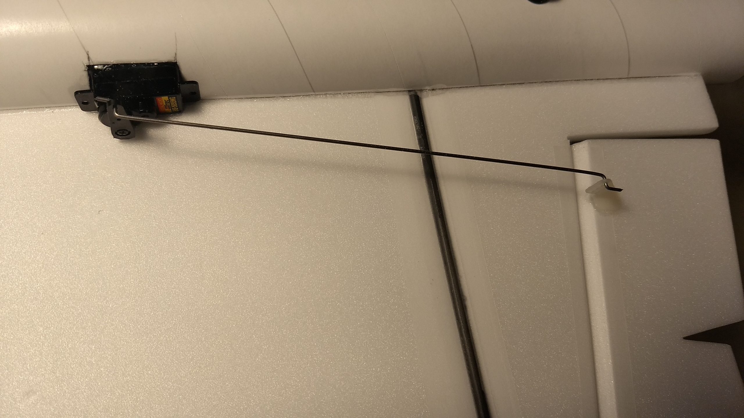
- Route the servo wire forward and glue the servo into the pocket.
-
- Repeat for the other side.
-
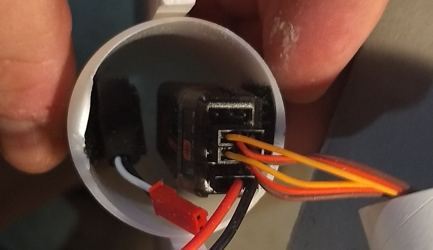
- Install the battery and receiver into the nose with velcro.
-
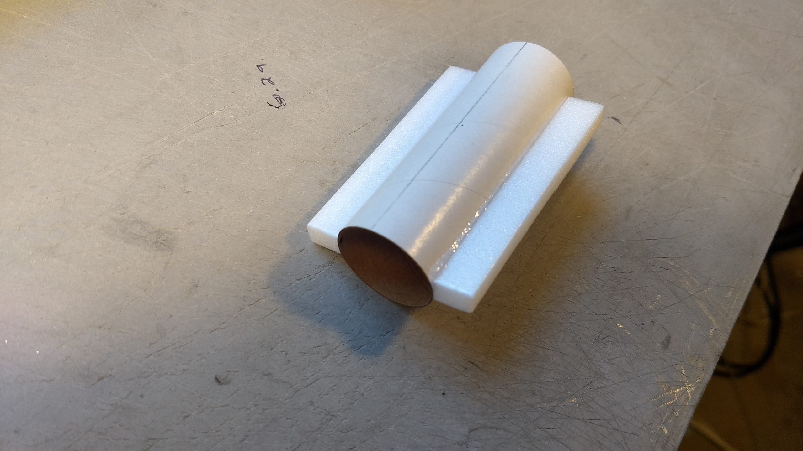
- Glue the two strips on opposite sides of the motor tube on the marked lines.
-
- Sand the foam tabs and then insert the motor tube from the rear into the slot in the wing, glue in place when correct.
-
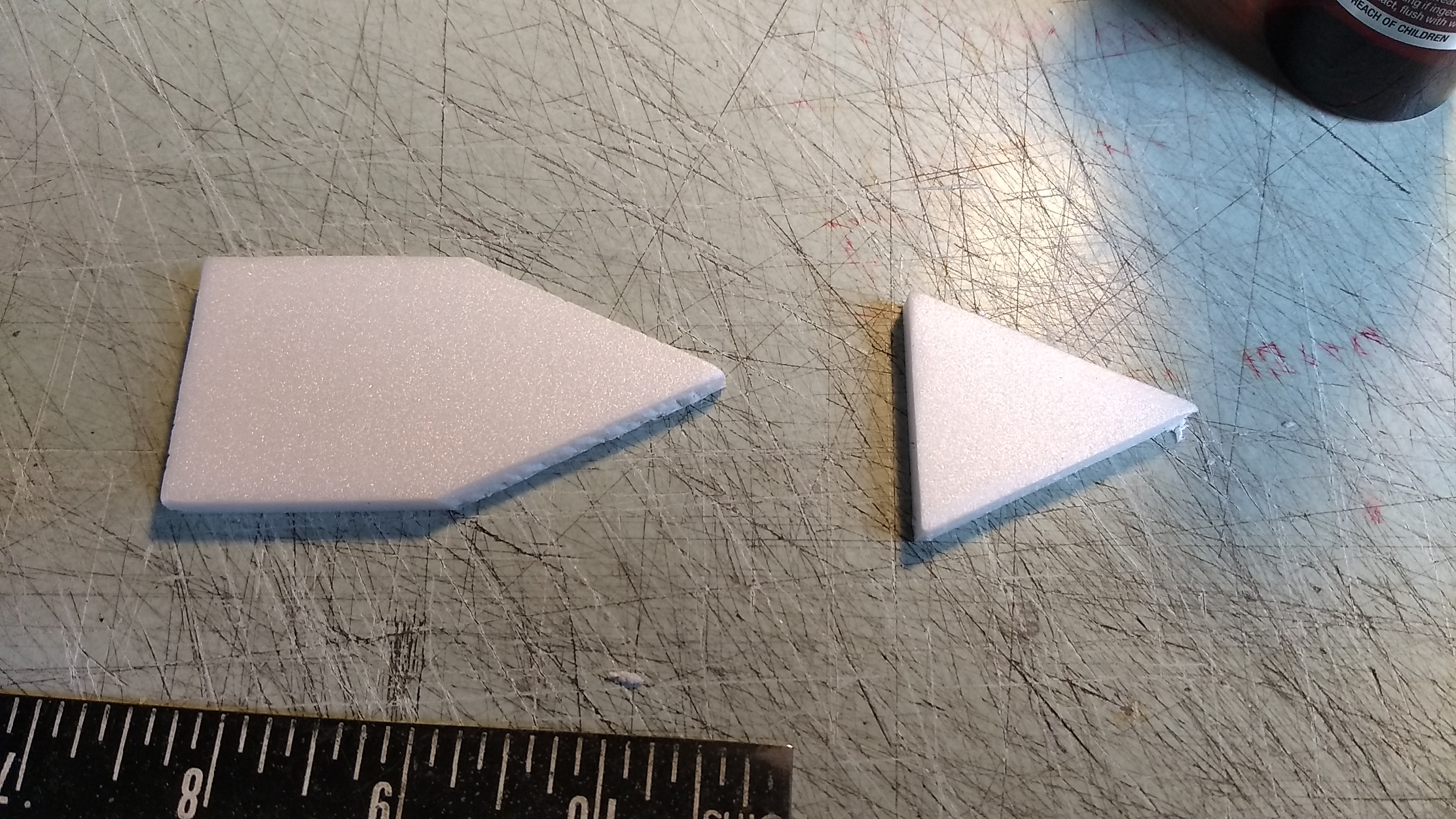
- Upper and lower intake cone pieces
-
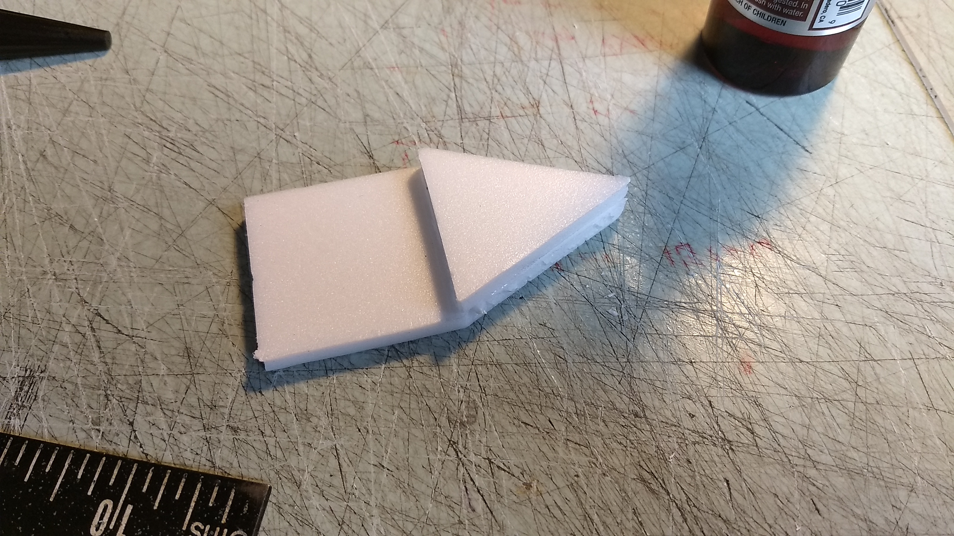
- Glue the two intake pieces together.
-
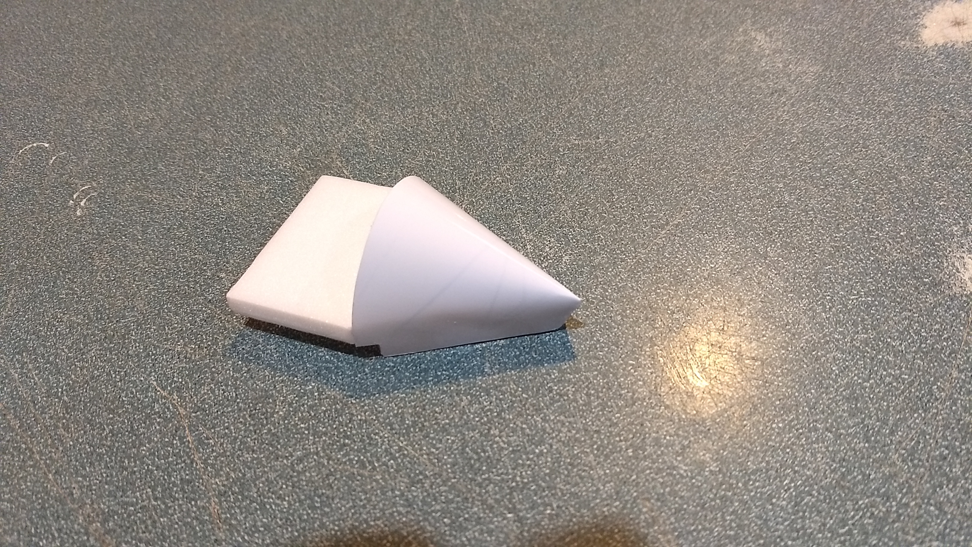
- Glue one side of the shroud so the bottom is even with the small step piece and the notch is even with the step. Wrap it around carefully and glue to the other side to complete the cone.
-

- Glue in the intake cone about 1/16″ from the inboard nacelle line marked on the wing and so the step is butted against the wing.
-
- Glue the nacelle tube so it is even with the drawn alignment line and flush with the front of the wing, then glue the other side of the tube. Repeat for other half of the wing.
-
- Install the two vertical stabs, note how they angle in, the actual angle isn’t critical but should be approx the same on both sides.
-
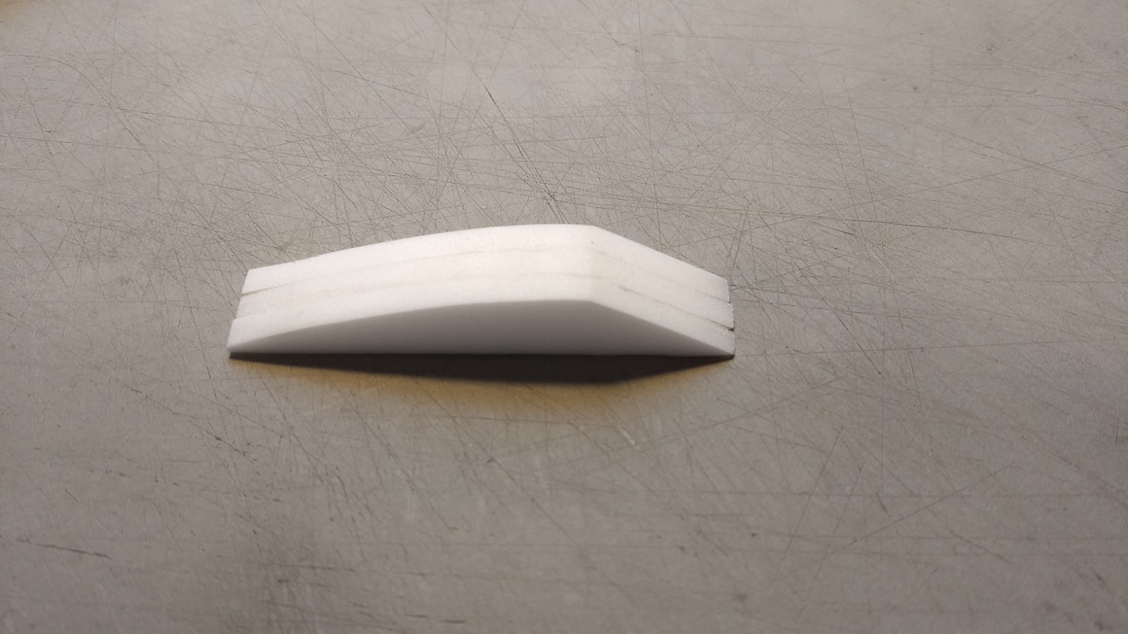
- Laminate cockpit pieces
-
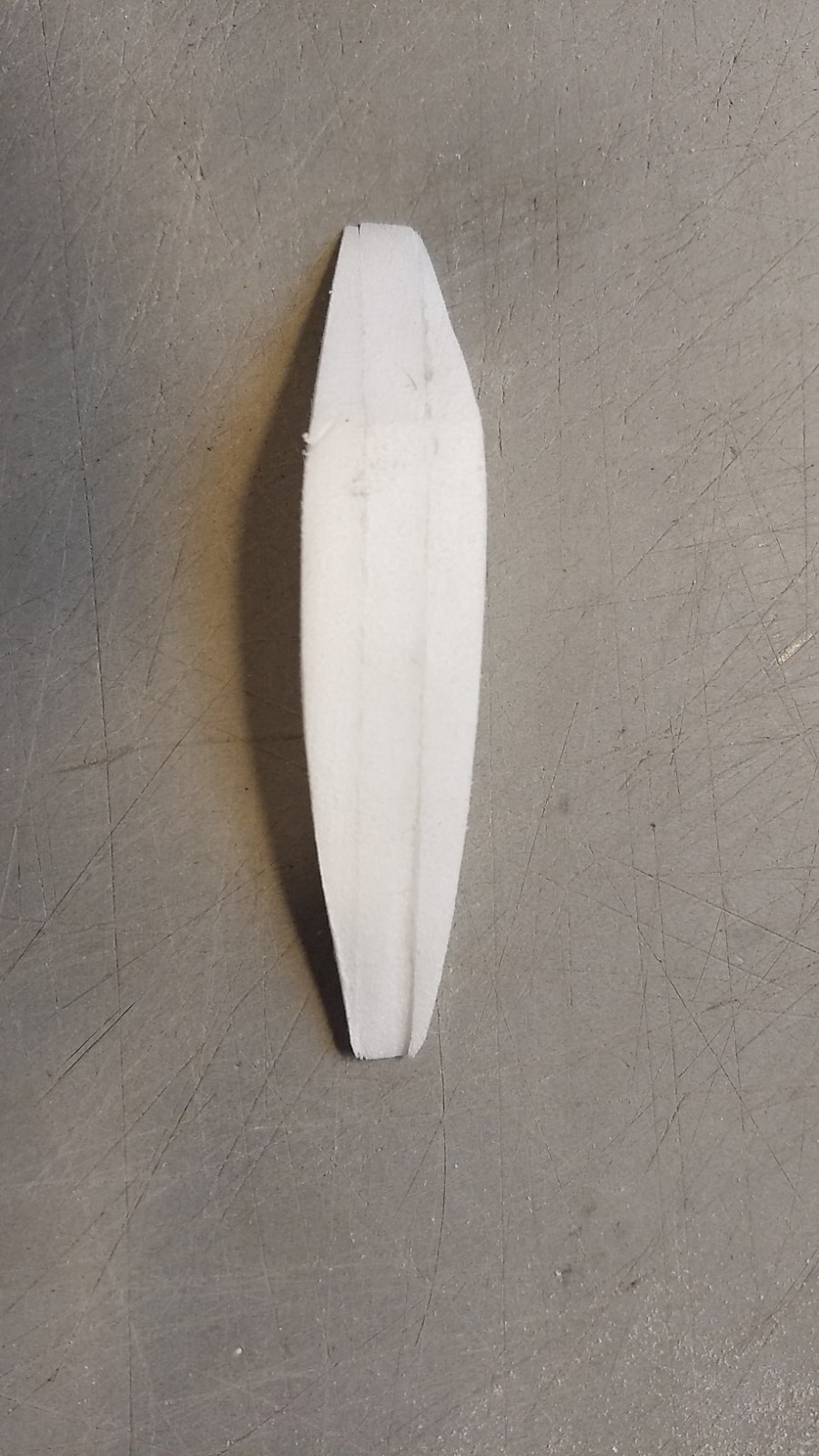
- Shape top view
-
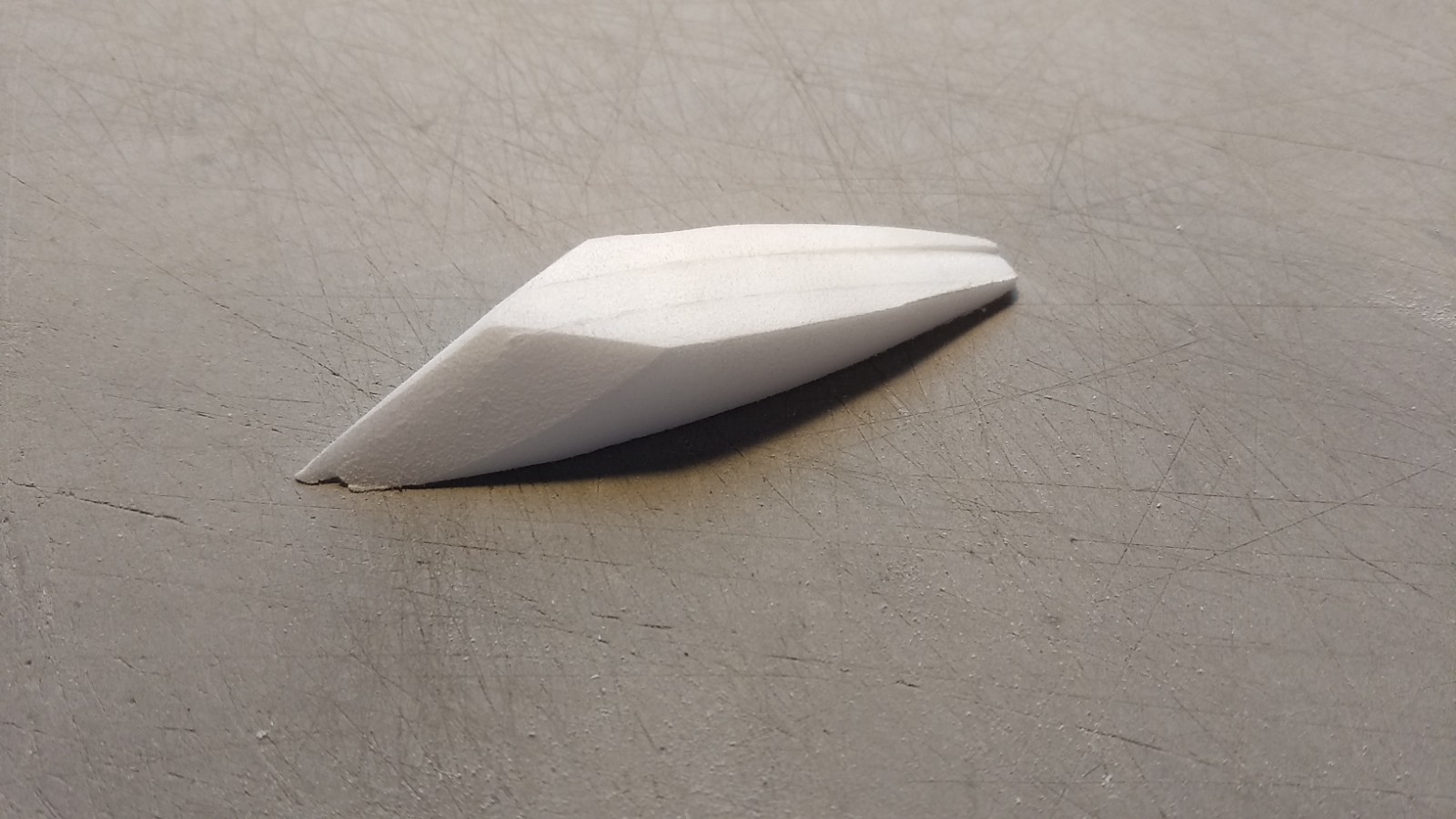
- angled front windows
-
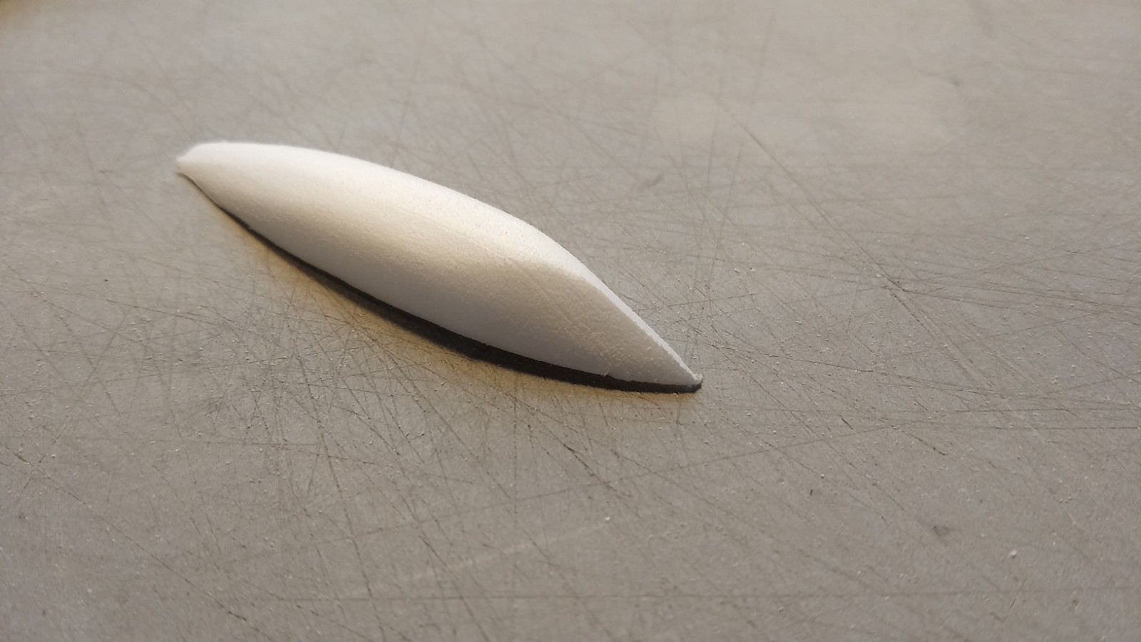
- Gently round the cockpit to shape
-
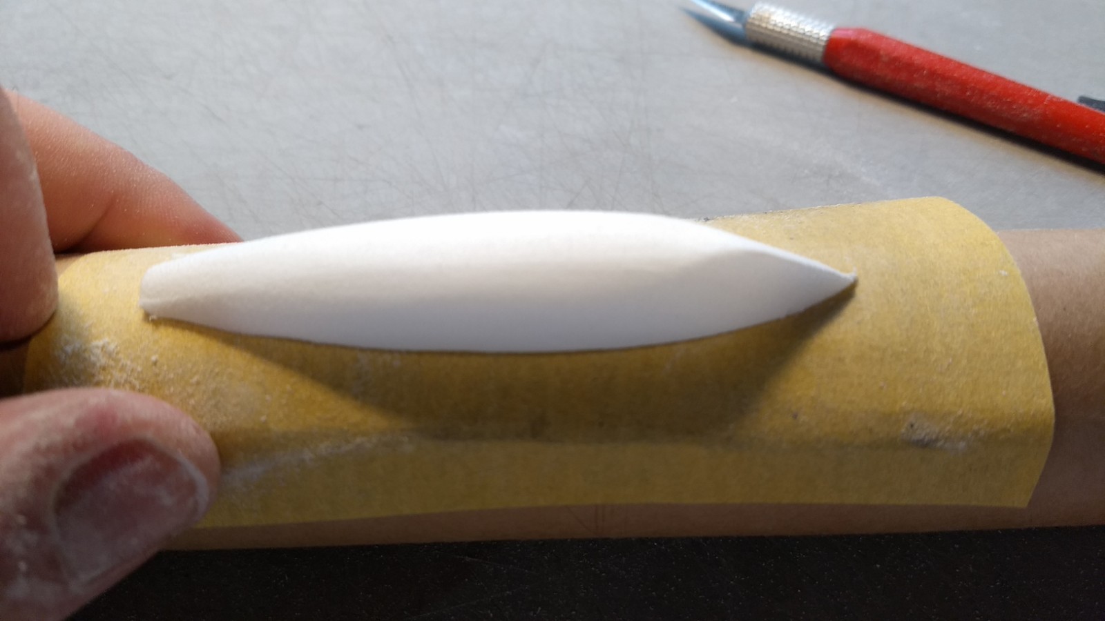
- wrap sandpaper over body tube and sand bottom to fit contour
-
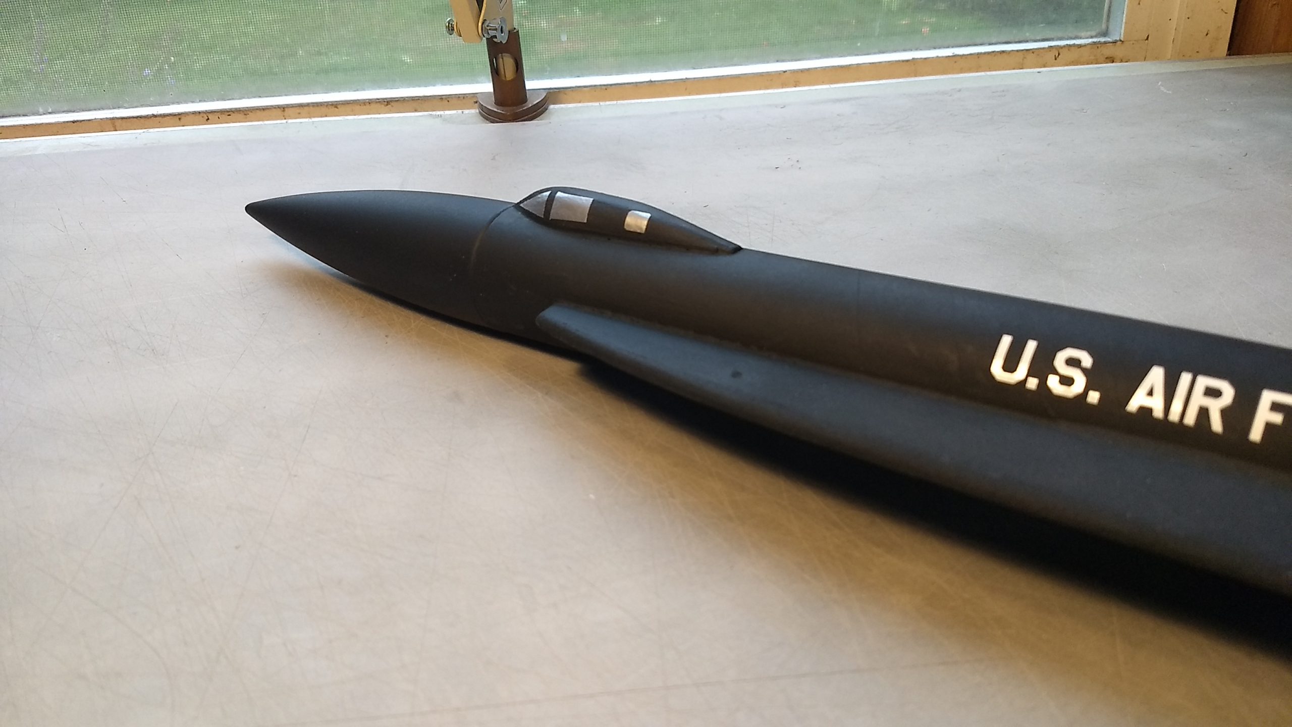
- Cockpit installed and decals applied after painting.
-
- Neutral boost trim
-
- Glide trim
-
- Left Aileron
-
- Right aileron
-
- Up elevator
-

- Down elevator
-
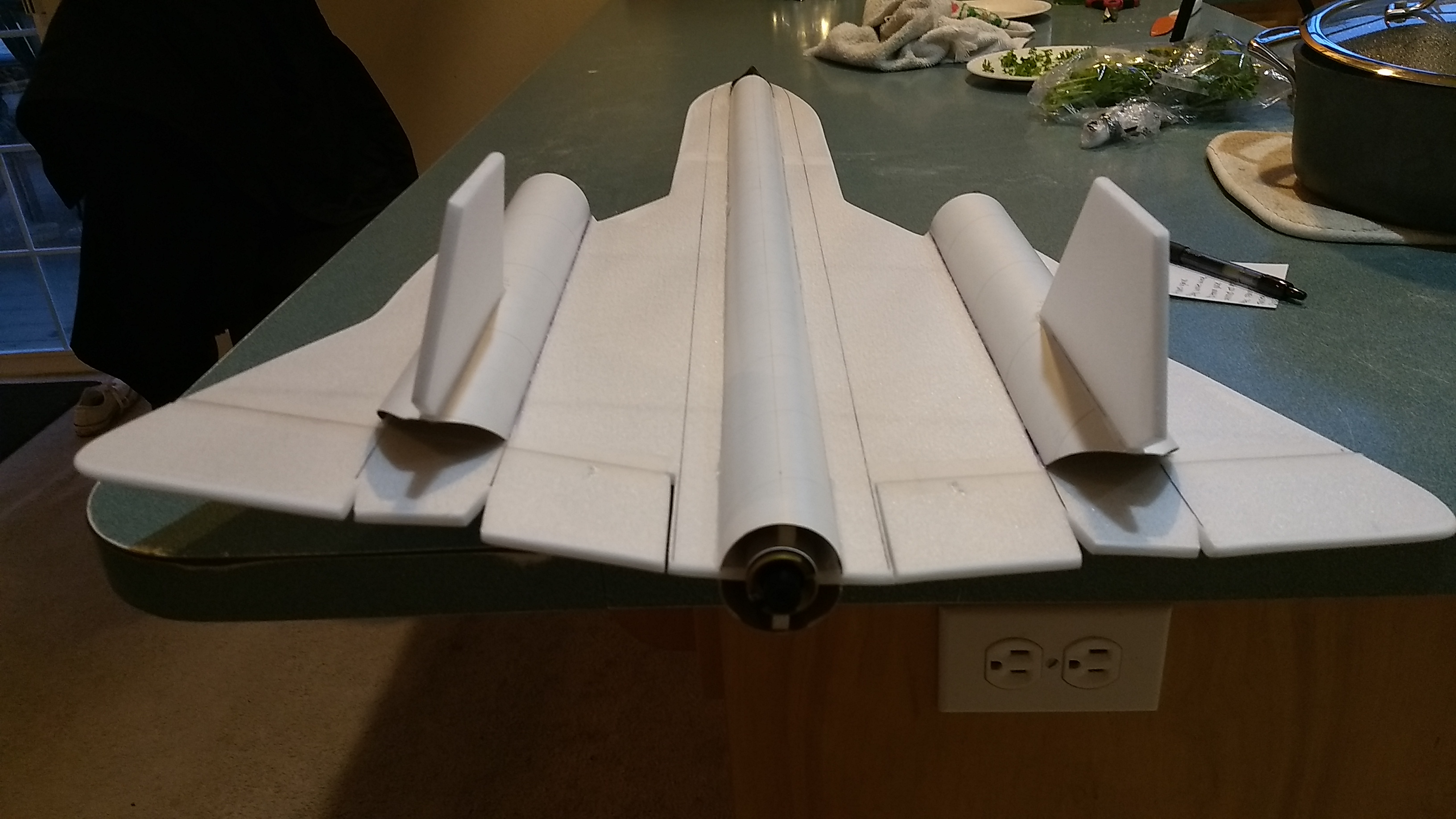
- Completed model
-
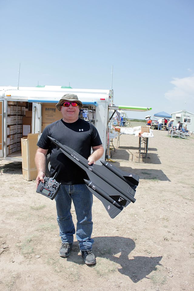
- Idea of the size of the model
-
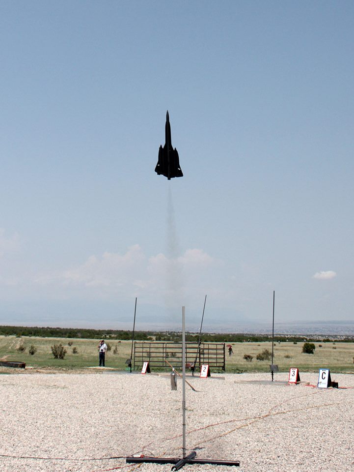
- Launch at NARAM 60
-
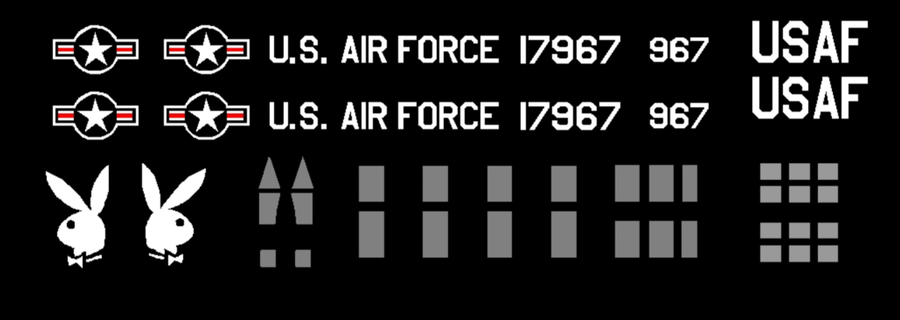
- example of stickershock decals